Table of Contents
Advertisement
Quick Links
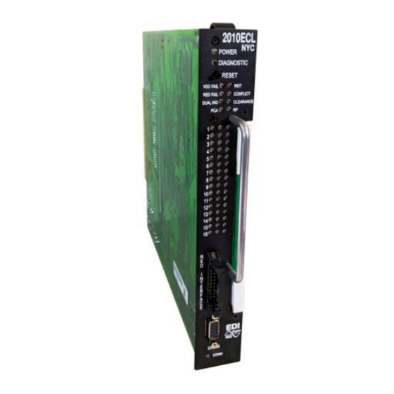
MODEL 2010ECL-NYC
RMS Signal Monitor
Operations Manual
THIS MANUAL CONTAINS TECHNICAL INFORMATION FOR THE FOLLOWING SERIES
OF MODEL 210/2010/2018 SIGNAL MONITORS, PCB Issue J:
2010ECL, 2010ECLip, 2018ECL, 2018ECLip
Firmware version 16AL43xx
- NOTE -
EDI ECCOM SOFTWARE MUST BE UPDATED TO VERSION 4.3 OR
GREATER FOR COMPATIBILITY WITH THIS FIRMWARE VERSION.
THE ECCOM SOFTWARE IS AVAILABLE FREE OF CHARGE AT
WWW.EDITRAFFIC.COM
REVISION: AUGUST 2019
pn 888-2010-115
Advertisement
Table of Contents

Subscribe to Our Youtube Channel
Related Manuals for EDI 2010ECL-NYC


Summary of Contents for EDI 2010ECL-NYC
- Page 1 OF MODEL 210/2010/2018 SIGNAL MONITORS, PCB Issue J: 2010ECL, 2010ECLip, 2018ECL, 2018ECLip Firmware version 16AL43xx - NOTE - EDI ECCOM SOFTWARE MUST BE UPDATED TO VERSION 4.3 OR GREATER FOR COMPATIBILITY WITH THIS FIRMWARE VERSION. THE ECCOM SOFTWARE IS AVAILABLE FREE OF CHARGE AT WWW.EDITRAFFIC.COM...
- Page 2 REGISTERED COMPANY INFORMATION CONTAINED HEREIN IS PROPRIETARY TECHNICAL INFORMATION OF EBERLE DESIGN INC. PUBLICATION, REPRODUCTION OR USE IN WHOLE OR PART IS NOT PERMITTED EXCEPT UNDER TERMS AGREED UPON IN WRITING. © COPYRIGHT 2019 EDI MAINTENANCE NOTE EBERLE DESIGN INC.
-
Page 3: Table Of Contents
3.2 Model 210ECL / 2010ECL /2018ECL Status/Event Reporting .......16 3.2.1 BI Tran Systems 233 Program Monitor Status..........16 3.2.2 EDI ECcom Monitor Report ................16 3.2.3 EDI ECcom Monitor Event Log Examples ............17 Section 4 INSTALLATION ....................20 4.1 Adapting Red Monitoring ..................20 4.1.1 Red Field Inputs ...................20... - Page 4 4.4.1 Red Fail Timing Switch ................21 4.4.2 Recurrent Pulse (RP) Disable Switch (RP DISABLE) ........21 4.4.3 WDT Timing Switch..................21 4.4.4 GY Enable Switch ..................21 4.4.5 FYAC MODE-H Switch ................21 4.4.6 LEDguard Switch ..................21 4.4.7 RF SSM Switch ....................22 4.4.8 FYA Mode Switch ..................22 4.5 Select Jumper Programming .................22 4.5.1 Watchdog Latch Select (SEL1) ..............22 4.5.2 Minimum Flash Enable Select (SEL2) ............22...
- Page 5 8.1.2 AC Voltage Monitors ..................31 8.1.3 DC Voltage Monitors ..................31 8.1.4 Outputs ......................31 8.2 Timing Functions ....................32 8.3 Mechanical ......................32 8.4 Environmental .......................32 Section 9 WIRING ASSIGNMENTS .................33 9.1 Monitor Unit Connector (P1) ..................33 9.1.1 Sixteen Channel ...................33 9.1.2 Eighteen Channel ..................34 9.2 Program Card Connector ..................34 9.2.1 Sixteen Channel ...................34 9.2.2 Eighteen Channel ..................35...
-
Page 6: Section 1 Basic Functions
2010ECL-NYC SERIES SIGNAL MONITOR OPERATIONS MANUAL Section 1 BASIC FUNCTIONS 1.1 MODEL DESCRIPTION The Signal Monitor consists of five models; the 210E, 210ECL, 2010, 2010ECL and 2018ECL. The model 210E is the base unit. The model 2010ECL and 2018ECL add an EIA-232 serial port that gives the unit the capability to communicate with a Controller Unit or PC based operational software for status and fault event data. -
Page 7: Controller Watchdog Monitoring (Wdt Error)
2010ECL-NYC SERIES SIGNAL MONITOR OPERATIONS MANUAL 1.2.3 CONTROLLER WATCHDOG MONITORING (WDT ERROR) Sensing of the controller Watchdog output is provided as specified in Section 4.3 of the Caltrans Traffic Signal Control Equipment Specifications. When a logic transition is not sensed for the specified period (see Section 8.2) the Signal Monitor will enter the fault mode causing the Output relay contacts to close and enabling the Stop-Time output to the controller. -
Page 8: Section 2 Extended Features
2010ECL-NYC SERIES SIGNAL MONITOR OPERATIONS MANUAL Section 2 EXTENDED FEATURES The following extended features are provided on the Signal Monitor to provide additional fault monitoring functions, to increase the reliability of the monitor operation, and enhance the diagnostic capabilities offered to the service technician. -
Page 9: Red Interface Cable Fault
2010ECL-NYC SERIES SIGNAL MONITOR OPERATIONS MANUAL Failure monitoring is disabled for all channels when the Red Enable input is not active, or the EE input (MC Coil) is active. 2.2.2 RED INTERFACE CABLE FAULT When inserted into the output file without the Red Interface cable assembly, the Signal Monitor will operate as a standard 210 Signal Monitor. -
Page 10: Ac Line Brown-Out Detection
2010ECL-NYC SERIES SIGNAL MONITOR OPERATIONS MANUAL A Clearance (short or absent Yellow) fault condition will place the Signal Monitor into the fault mode causing the Output relay contacts to close and enabling the Stop-Time output to the controller. This occurs when a Red input signal to a channel is active following the termination of an active Yellow input signal which is less than the minimum duration, including zero (i.e. -
Page 11: Exit Flash
2010ECL-NYC SERIES SIGNAL MONITOR OPERATIONS MANUAL function is designed to respond to fault conditions which are intermittent in nature and do not meet the continuous timing requirements of the normal detection algorithms, yet may still produce improper signal displays. These input conditions are differentiated by their longer time constant and fault response times. -
Page 12: Configuration Change Monitoring
2010ECL-NYC SERIES SIGNAL MONITOR OPERATIONS MANUAL 2.11 CONFIGURATION CHANGE MONITORING The Signal Monitor maintains an internally calculated CRC value of the current configuration settings. These settings include the permissive diode matrix, SSM switches, Yellow Disable switches, Option switches, SEL1 through SEL16 jumpers, and the Watchdog Enable switch. -
Page 13: Watchdog Monitoring Disabled Indicator
2010ECL-NYC SERIES SIGNAL MONITOR OPERATIONS MANUAL 2.16 WATCHDOG MONITORING DISABLED INDICATOR When the WDT ENABLE switch is in the OFF position to disable Watchdog Monitoring of the cabinet Controller, or the AC Line voltage is below the Watchdog disable level, the Signal Monitor will flash the WDT ERROR indicator on the front panel once every 2 seconds. -
Page 14: Diagnostic Display Mode (210Ecl / 2010Ecl /2018Ecl)
2010ECL-NYC SERIES SIGNAL MONITOR OPERATIONS MANUAL Triple flash (G) AC POWER LED flashes Green field status 1-16 Triple flash (Y) VDC FAILED LED flashes Yellow field status 1-16 Triple flash (R) WDT ERROR LED flashes Red field status 1-16 (repeats back to top) To enter this display mode remove the Program Card. -
Page 15: Flashing Yellow Arrow (Fya) Overview
A Flashing Yellow Arrow approach is actually monitored using two physical channels of the Signal Monitor. In the NYCDOT 2010ECL-NYC, the Ped Yellow load switch outputs of channels 9-12 are remapped to channels 13-16 Green (when enabled) to monitor the protected Green arrow signals. -
Page 16: Fya Mode
Green protected Arrow is driven by a Ped load switch input on channels 9, 10, 11, and 12. The NYCDOT 2010ECL-NYC will remap these Ped Yellow inputs to be monitored by channels 13, 14, 15, and 16 respectively. Inputs to channel 9-12 Yellow will be forced to 0 Vac. - Page 17 2010ECL-NYC SERIES SIGNAL MONITOR OPERATIONS MANUAL the enabled flashing yellow arrow signals on channels 1, 2, 3, and 4 remain active for more than the FYA Flash Rate Fault time (Section 8.2), the Signal Monitor will enter the fault mode, transfer the OUTPUT relay contacts to the Fault position, and display status.
-
Page 18: Fyac (Compact) Mode
Green protected Arrow is driven by a Ped load switch input on channels 9, 10, 11, and 12. The NYCDOT 2010ECL-NYC will remap these Ped Yellow inputs to be monitored by channels 13, 14, 15, and 16 respectively. Inputs to channel 9-12 Yellow will be forced to 0 Vac. - Page 19 2010ECL-NYC SERIES SIGNAL MONITOR OPERATIONS MANUAL 2.20.2.1.2 FLASH RATE DETECTION When the FLASHRATE FAULT option is not disabled (see Section 4.5.7), the Signal Monitor will monitor a flashing yellow arrow output (1,3,5,7) for a lack of flashing operation. If any of the enabled flashing yellow arrow signals on channels 1,3,5,7 remain active for more than the FYA Flash Rate Fault time (Section 8.2), the Signal Monitor will enter the fault mode,...
-
Page 20: Fyac (Compact) Mode-H
2010ECL-NYC SERIES SIGNAL MONITOR OPERATIONS MANUAL - WARNING - IF THE PERMISSIVE FLASHING YELLOW ARROW AND PROTECTED GREEN ARROW CHANNEL ASSIGNMENTS ARE SWAPPED SUCH THAT THE FYA INPUT IS MONITORED ON CHANNELS 13:16 GREEN: 1) The Flashrate Fault function monitors the enabled flashing Yellow Arrow input of channels 1, 3, 5, 7. -
Page 21: Section 3 Event Logging Features
3.2.2 EDI ECCOM MONITOR REPORT The EDI ECcom software package (Version 3.8 or greater is required) interfaces a Computer to the “ECL” and “ECLip” models. The ECcom program will display the Status (S), Previous Fault (PF) event log, AC Line (AC) event log, Manual Reset (MR) event log, Configuration (CF) event log, and Fault Trace log. -
Page 22: Edi Eccom Monitor Event Log Examples
1) Previous Fault (PF) Event Log >> Previous Fail Event Log >> Monitor ID #73 >> EDI Model 2010ECL, Firmware Type 01, Firmware V5.0, Comm V3.6 >> RMS-Engine Firmware Type 01, RMS-Engine Firmware V2.3 >> ECcom Version 3.6.2 >> Downloaded at 10:23:35 AM Friday, September 22, 2006 >>... - Page 23 2010ECL-NYC SERIES SIGNAL MONITOR OPERATIONS MANUAL >> EDI Model 2010ECL, Firmware Type 01, Firmware V5.0, Comm V3.6 >> RMS-Engine Firmware Type 01, RMS-Engine Firmware V2.3 >> ECcom Version 3.6.2 >> Downloaded at 10:21:27 AM Friday, September 22, 2006 >> Number of events = 2...
- Page 24 2010ECL-NYC SERIES SIGNAL MONITOR OPERATIONS MANUAL Yellow Disable (X=Disable): 9 10 11 12 13 14 15 16 Unit Data: Red Fail Fault Timing = 1200-1500 ms Recurrent Pulse = ENABLED Watchdog Timing = 1.5 seconds GY Enable = DISABLED *>...
-
Page 25: Section 4 Installation
2010ECL-NYC SERIES SIGNAL MONITOR OPERATIONS MANUAL Section 4 INSTALLATION The Signal Monitor is a plug-in module for the Type 170/179 output file. When inserted into the output file without the Red Interface cable assembly, it will operate as a standard 210 Signal Monitor. -
Page 26: Yellow Disable Jumpers
4.4.5 FYAC MODE-H SWITCH Switch #5 of SW3 is labeled "FYAC MODE-H". NYCDOT: This switch is non-functional. FYA Mode H is not provided in the 2010ECL-NYC. 4.4.6 LEDGUARD SWITCH Switch #6 of SW3 is labeled "LEDguard". When this switch is in the ON position, the ®... -
Page 27: Rf Ssm Switch
4.5 SELECT JUMPER PROGRAMMING The Signal Monitor also provides jumper options to modify the monitor operation. The Select jumpers are labeled SEL1 through SEL16. SEL6 through SEL16 are reserved for EDI configuration programming and should not be modified except by the factory. -
Page 28: Ee Input Polarity Select (Sel9)
2010ECL-NYC SERIES SIGNAL MONITOR OPERATIONS MANUAL AC Line Brown-out levels will be set for the 210E series with Dropout at 92 + _ 2 Vrms and Restore at 98 + _ 2 Vrms with timing at 80 _ + 17 ms. See Section 2.5. -
Page 29: Section 5 Front Panel Description
2010ECL-NYC SERIES SIGNAL MONITOR OPERATIONS MANUAL Section 5 FRONT PANEL DESCRIPTION 5.1 INDICATORS 5.1.1 (G) AC POWER INDICATOR The AC POWER indicator will illuminate when the AC Line voltage level is above the brown- out "restore" level. The indicator will flash at a rate of 2Hz when the AC Line voltage is below the "drop-out"... -
Page 30: Pca Indicator
2010ECL-NYC SERIES SIGNAL MONITOR OPERATIONS MANUAL 5.1.8 PCA INDICATOR The PCA indicator will illuminate if the Program Card is absent or not properly seated. A manual Reset is required after the program card is properly seated. If the unit is in the Diagnostic Display mode, the PCA indicator will flash ON (once, twice, or three times) to indicate the fault event number being displayed. -
Page 31: Red Interface Connector (P8)
2010ECL-NYC SERIES SIGNAL MONITOR OPERATIONS MANUAL 5.3 RED INTERFACE CONNECTOR (P8) This connector provides the required inputs for the Signal Monitor to monitor the Red Field Signal outputs. It is polarized to insure proper mating with the adapter cable. Ejector latches are included to facilitate removal and prevents the cable from inadvertently disconnecting. -
Page 32: Section 6 Circuit Operation
2010ECL-NYC SERIES SIGNAL MONITOR OPERATIONS MANUAL Section 6 CIRCUIT OPERATION 6.1 INTRODUCTION The Signal Monitor uses a dual microprocessor architecture consisting of an 68HC11D0 main microprocessor unit (MPU) and a Microchip PIC17F242 based RMS-Engine. The RMS- Engine is a dedicated single-chip high speed microcontroller used to sample the AC field inputs and calculate the true Root Mean Squared (RMS) voltage. -
Page 33: Real Time Clock
2010ECL-NYC SERIES SIGNAL MONITOR OPERATIONS MANUAL 6.7 REAL TIME CLOCK The DS1305 Real Time Clock (U29) provides the timekeeping function. It transfers data to the main MPU using the serial SPI interface. During normal operation the RTC is synchronized to the 60 Hz AC Line for long term accuracy. The lifetime lithium battery (BATT1) provides power to the RTC when AC Line voltage is not present. -
Page 34: Section 7 Trouble Shooting
2010ECL-NYC SERIES SIGNAL MONITOR OPERATIONS MANUAL Section 7 TROUBLE SHOOTING SYMPTOMS: Will not power on CAUSES: Blown fuse Internal power supply is low No AC input to the monitor SOLUTIONS: Remove the fuse and verify with an Ohm meter. Replace if necessary with a fuse with the same current rating. - Page 35 2010ECL-NYC SERIES SIGNAL MONITOR OPERATIONS MANUAL CAUSES: Diode on the Program Card is open or absent SOLUTIONS: Check the program card to verify that the required diode is in place. If the diode is present then verify all connections are good and the diode is working correctly.
-
Page 36: Section 8 Specifications
2010ECL-NYC SERIES SIGNAL MONITOR OPERATIONS MANUAL Section 8 SPECIFICATIONS 8.1 ELECTRICAL 8.1.1 POWER REQUIREMENTS Operating Line Voltage ................. 75 to 135 Vrms Operating Line Frequency ..................60 _ + 3Hz Power Consumption ..................5W (nominal) 8.1.2 AC VOLTAGE MONITORS Green Signal Inputs (no detect) ........ -
Page 37: Timing Functions
2010ECL-NYC SERIES SIGNAL MONITOR OPERATIONS MANUAL 8.2 TIMING FUNCTIONS Conflict (no fault) ........less than 200 milliseconds (fault) ........greater than 500 milliseconds (typical) ............350 milliseconds VDC Failed (no fault) ........less than 200 milliseconds (fault) ........greater than 500 milliseconds (typical) ............ -
Page 38: Section 9 Wiring Assignments
2010ECL-NYC SERIES SIGNAL MONITOR OPERATIONS MANUAL Section 9 WIRING ASSIGNMENTS 9.1 MONITOR UNIT CONNECTOR (P1) Output Relay SIDE #3 contact OPENS when the unit is in the fault state. SIDE #1 contact CLOSES when the unit is in the fault state. -
Page 39: Eighteen Channel
2010ECL-NYC SERIES SIGNAL MONITOR OPERATIONS MANUAL Card mate with a 28/56 pin double sided edge-card connector having 0.156" centers. OUTPUT SW, SIDE #1 closes in the fault mode. OUTPUT SW, SIDE #3 opens in the fault mode. 9.1.2 EIGHTEEN CHANNEL... -
Page 40: Eighteen Channel
2010ECL-NYC SERIES SIGNAL MONITOR OPERATIONS MANUAL Pin # Function Pin # Function CHANNEL 7 GREEN CHANNEL 6 GREEN CHANNEL 8 GREEN CHANNEL 7 GREEN CHANNEL 9 GREEN CHANNEL 8 GREEN CHANNEL 10 GREEN CHANNEL 9 GREEN CHANNEL 11 GREEN CHANNEL 10 GREEN... -
Page 41: Red Interface Connector (P8)
2010ECL-NYC SERIES SIGNAL MONITOR OPERATIONS MANUAL Pin # Function Pin # Function CHANNEL 8 YELLOW CHANNEL 16 YELLOW CHANNEL 17 GREEN CHANNEL 17 YELLOW CHANNEL 18 GREEN CHANNEL 18 YELLOW CHANNEL 16 GREEN PROGRAM CARD YELLOW INHIBIT COMMON CHANNEL 17 GREEN Mating connector shall be keyed between pins 24 and 25 and also BB and CC. -
Page 42: Eia-232 Cable To A Pc
9.5 ETHERNET LAN PORT The Ethernet port must be configured with specific network parameters such as an IP address. The network port parameters are set or changed using the EDI ECcom Signal Monitor Communications software. See the "EDI ECcom Software Operations Manual" for details on the SETUP / COMM PORT / SETTINGS / Search function. - Page 43 2010ECL-NYC SERIES SIGNAL MONITOR OPERATIONS MANUAL Eberle Design Inc. Page 38...
Need help?
Do you have a question about the 2010ECL-NYC and is the answer not in the manual?
Questions and answers