
Related Manuals for Ropox Vario 40-30604


Summary of Contents for Ropox Vario 40-30604
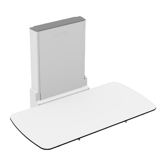
- Page 1 Ropox Vario User manual This manual should always be in close proximity of the product. TF 200.01.0018_ENG / 26-07-2022...
-
Page 2: Table Of Contents
Table of content Symbols used in this manual ........................4 General safety ............................4 Product label ..........................6 General requirements ..........................7 3.1 Product information ........................7 3.2 Intended use..........................8 3.3 Intended operator .......................... 8 3.4 Dimensions ............................ 9 3.4.1 Without bed guard ........................ - Page 3 10.3 Mattress ............................. 24 11. Electromagnetic compatibility ......................25 11.1 Suitable Environments ......................25 11.2 Basic safety and Essential performance ................25 11.3 Adjacent and stacked use ....................25 11.4 Cables ..........................25 11.5 RF portable equipment ......................25 12. Complaints .............................. 26 TF 200.01.0018_ENG...
-
Page 4: Symbols Used In This Manual
1. Symbols used in this manual Warning Symbol Indication of potentially hazardous situation. If not avoided, it can result in serious injury or death. Caution Symbol Indication of potentially hazardous situation which may result in minor or moderate injury. It may also be used to alert against unsafe practices. Notification Symbol This symbol is used to notify correct use and handling of the product. - Page 5 The information in this manual is based on correct installation in accordance with installation instructions for this product. Ropox cannot be held liable if the product is used in any way that differs from stated in this manual and/or installation instruction.
-
Page 6: Product Label
2.1 Product label This product is UKCA-marked in accordance with: UK SI 2002 No. 618 - The Medical Devices Regulations 2002, and its amendments UK SI 2008 No. 1597 - The Supply of Machinery (Safety) Regulations 2008, and its amendments This product is CE-marked in accordance with: European Medical Device Directive 93/42/EEC, including amendments incorporated in Directive 2007/47/EEC. -
Page 7: General Requirements
Consult the instructions for use 3. General requirements 3.1 Product information Manufacturer Ropox A/S Ringstedgade 221, DK-4700 Naestved +45 55 75 05 00 Info@ropox.com Product models Part number Model Configuration 40-30604 Vario 120x70cm 40-30606 Vario 140x70cm 40-30608 Vario 160x70cm 40-30610... -
Page 8: Intended Use
Accessories Mattresses 40-25760-1 For L= 120cm 40-25795-1 For L= 140cm 40-25796-1 For L= 160cm 40-25764-1 For L= 180cm 40-25765-1 For L= 190cm Bed guards 40-30196-1 For L=120cm, 140cm 40-30197-1 For L=160cm, 180cm, 190cm Cushion for bed guard 40-25782-1 For L=120cm, 140cm 40-25783-1 For L=160cm, 180cm, 190cm 3.2 Intended use... -
Page 9: Dimensions
3.4 Dimensions 3.4.1 Without bed guard 32cm 13cm Model Length(L) 40-30604 120cm 40-30606 140cm 40-30608 160cm 40-30610 180cm 40-30611 190cm 3.4.2 With bed guard Model Length 40-30804 120cm 40-30806 140cm 40-30808 160cm 40-30810 180cm 40-30811 190cm TF 200.01.0018_ENG... -
Page 10: Instructions For Use
4. Instructions for use Receiving the Vario changing bed Vario is a wall fixed changing bed. It is delivered partly assembled. Connecting the product to mains will make it operational. Vario will come in two packages. One for the “Lifting unit” and one for the “tabletop”. Note! The ceiling height must be at least 2.35m. -
Page 11: Placement Behind Lifting Unit
4.2.2 Placement behind lifting unit The following drawing illustrates the space that can be allocated for an electrical outlet without interfering with the movement of the unit. The blue-hatched area is the safe are for placing an electrical outlet and cover. -
Page 12: Assembly Preparations
4.3 Assembly preparations 4.3.1 Dismount the top cover plate 4.3.2 Dismount the front plate Slide the front plate out of the Lifting unit to get access to the wall mounting holes in the unit !! Be aware not to bend or scratch the front plate in the process !! TF 200.01.0018_ENG... -
Page 13: Mounting To The Wall
4.4 Mounting to the wall The attachment holes can be marked up on the wall, four possibilities in the top, and four in the bottom of the frame. Place the frame against the wall and make sure it is horizontal. The frame is standing on two adjustable feet. -
Page 14: Mount The Lifting Unit To The Wall With Screws At The Top And Bottom
4.4.1 Mount the lifting unit to the wall with screws at the top and bottom TF 200.01.0018_ENG... -
Page 15: Slide The Front Plate Back Into The Lifting Unit
4.4.2 Slide the front plate back into the lifting unit 4.4.3 Mount the cover plate on the top of the lifting TF 200.01.0018_ENG... -
Page 16: Mount The Tabletop On The Lifting Unit
4.5 Mount the tabletop on the lifting unit Slide the tabletop in between the Lifting unit and the support arms on the Lifting unit. Fasten the tabletop to the Lifting unit with 4 pcs. Screws (M8x12) through the bushings in the support arms. -
Page 17: Wire Diagram
4.6 Wire diagram The changing bed is delivered with the control box already mounted on the frame. The diagram shows how the cables are connected to the control box. All the plugs are watertight, and therefore they can be a little tricky to connect / disconnect. -
Page 18: Connecting Cables
4.6.1 Connecting cables The changing bed is delivered with the control box already mounted on the frame. Control switch connects to ”HB”. Mains cable connects to the socket at the side of the box. Caution! To obtain the full IPX6 value, it is very important that all the plugs have been pressed firmly into the sockets until the “O-ring”... -
Page 19: Instructions For Use
5. Instructions for use Warning! Before use always make sure that mains cable and hand control cable will be able to travel freely without the risk of squeezing or disconnecting the product as result of the movement. Operating the product 5.1.1 Actuation of the product The product is operated with the spiral cord hand control. -
Page 20: Operation Of The Bed Guards
5.1.2 Operation of the bed guards Vario is not supplied with bed guard as standard. This can be ordered as an accessory. To operate the bed guards, pull the rubber tubing placed under the tabletop to release the locking mechanism. The bed guard can then be pivoted to the desired mode. Warning! Make sure that the bed guard is locked securely in place when in use. -
Page 21: Locking Of Shower Bed
5.1.4 Locking of shower bed When worktop is folded up, insert locking pin as indicated. Press and hold the red button while inserting the split. The shower bed is now locked against folding down. 5.1.5 Unlocking of shower bed For unlocking & folding worktop in downwards position, remove pin. Pin is placed in second hole for storage when shower bed is being used and folded down. -
Page 22: Cleaning
6. Cleaning Cleaning can be done with lukewarm water and a suitable all-purpose cleaning agent. Use a cloth or soft sponge to wash the product. Dry the product of with a wrung cloth. Mattresses and cushions Cover: Recommended cleaning detergent: Normal soap or alcohol. The alcohol can be used undiluted. The cover can be removed, and machine washed separately at max 95°. -
Page 23: Environmental Protection
8. Environmental protection The product is not intended to be disposed as municipal waste. Proper disassembly, sorting and disposal of components must be done by waste disposal professionals. Part Disposal recommendation Tabletop Hard plastic or phenolic composites Bed guards Steel waste Lifting unit Steel and aluminum Controlbox... -
Page 24: Accessories
10. Accessories 10.1 Bed guard Part number Size Pcs. 40-30196-1 L= 120cm, 140cm 40-30197-1 L= 160cm, 180cm, 190cm 10.2 Cushion for bed guard Item number Size Pcs. 40-25782-1 L= 120cm, 140cm 40-25783-1 L= 160cm, 180cm, 190cm 10.3 Mattress Item number Size Thickness 40-25760-1... -
Page 25: Electromagnetic Compatibility
11. Electromagnetic compatibility 11.1 Suitable Environments The device is suitable for use at home, at daycare centers, at day centers for persons with physical or mental disabilities or at hospitals except near active HF surgical equipment and the RF shielded room of a medical electrical system for magnetic resonance imaging, where the intensity of electromagnetic disturbances is high. -
Page 26: Complaints
12. Complaints See our general terms of sale and delivery on www.ropox.com ROPOX A/S Ringstedgade 221 DK – 4700 Næstved Phone.: +45 55 75 05 00 Fax.: +45 55 75 05 50 E-mail: info@ropox.dk www.ropox.com TF 200.01.0018_ENG...
Need help?
Do you have a question about the Vario 40-30604 and is the answer not in the manual?
Questions and answers