Table of Contents
Advertisement
Quick Links
INSTALLATION
MANUAL
CONTENTS
GENERAL . . . . . . . . . . . . . . . . . . . . . . . . . . . . . . . . . . . .4
SAFETY CONSIDERATIONS . . . . . . . . . . . . . . . . . . . . .4
AGENCY APPROVALS . . . . . . . . . . . . . . . . . . . . . . . . . .4
INSPECTION . . . . . . . . . . . . . . . . . . . . . . . . . . . . . . . . . .4
INSTALLATION . . . . . . . . . . . . . . . . . . . . . . . . . . . . . . .5
MAINTENANCE . . . . . . . . . . . . . . . . . . . . . . . . . . . . . .17
See the following page for a complete Table of Contents.
NOTES, CAUTIONS AND WARNINGS
The installer should pay particular attention to the words:
NOTE, CAUTION, and WARNING. Notes are intended to
clarify or make the installation easier. Cautions are given
to prevent equipment damage. Warnings are given to
alert installer that personal injury and/or equipment dam-
age may result if installation procedure is not handled
properly.
CAUTION:
READ ALL SAFETY GUIDES BEFORE YOU
BEGIN TO INSTALL YOUR UNIT.
SAVE THIS MANUAL
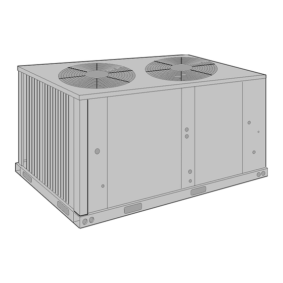
SPLIT-SYSTEM
CONDENSING UNITS
(AIR COOLED)
MODEL: HF-07
208/230/460
VOLT ONLY
208/230/460
VOLT ONLY
035-18518-001-B-0703
Advertisement
Table of Contents

Related Manuals for Unitary products group HF-07


Summary of Contents for Unitary products group HF-07
- Page 1 CONDENSING UNITS (AIR COOLED) MODEL: HF-07 CONTENTS GENERAL ........4 SAFETY CONSIDERATIONS .
-
Page 2: Table Of Contents
REFRIGERANT-22 LINE CHARGE ....11 CRANKCASE HEATER ..... . . 15 Unitary Products Group... -
Page 3: Nomenclature
Nominal Heating 00 = No Heat Installed Capacity Airflow Options A = None Voltage 6 = 208/230-460-3-60 Installation Options A = None Additional Options AA = None Product Generation 1 = 1st Generation 2 = 2nd Generation Unitary Products Group... -
Page 4: General
A separate request for inspection by the carrier's agent should be made in writing. See Form 50.15-NM for more information. Unitary Products Group... -
Page 5: Installation
Refer to “REFRIGERANT PIPING” for crete slab with a minimum thickness of 4 inches. The additional information. length and width should be at least 6 inches greater than the units overall base dimensions. Refer to Figure 4. Unitary Products Group... -
Page 6: Rigging And Handling
MUST be used across the top of the unit if the that it will lift evenly. rigging height above the top of the unit is less than 5 feet. See Figure 2. Unitary Products Group... -
Page 7: Clearances
5-3/8 7/8 DIA CONTROL WIRING ENTRY COMPRESSOR AND 2-1/4 5-7/8 CONDENSER FAN MOTOR 32-1/2 70-1/2 ACCESS 1-3/8 DIA. 7/8" KNOCKOUT POWER WIRING ACCESSORY WIRING ENTRY ENTRY CONDENSER FAN MOTOR ACCESS FIGURE 4 - UNIT DIMENSIONS AND CLEARANCES Unitary Products Group... -
Page 8: Compressor
Follow manufacturer's data on Table 3. instructions enclosed with thermostat for general instal- lation procedure. Copper conductors must be installed between NOTE: the disconnect switch and the unit. Refer to Figure 5 for typical field wiring. Unitary Products Group... -
Page 9: Typical Field Wiring With La Air Handler
The 208-230 V compressors and motors use a single tap for the entire range of voltages. The 208/230 V to 24 V transformers have different taps for 208 and 230 V. †. Dual element, time delay type. Unitary Products Group... -
Page 10: Refrigerant Piping
ALWAYS USE A REFRIGERATION VALVE WRENCH TO OPEN AND CLOSE THESE SERVICE VALVES. Unitary Products Group... -
Page 11: Suction Lines
Charges are based on 40°F suction temperature and 105°F liquid temperature. †. Type “L” copper tubing. NOTE: Add the operating charge of the condensing unit, the evaporator coil and the refrigerant lines to determine the total refrigerant charge for the system. Unitary Products Group... -
Page 12: Extending The Service Ports
7. Move the dry nitrogen supply back to the access Clean surfaces are essential for a well-brazed NOTE: port on the liquid line service valve. connection. Unitary Products Group... -
Page 13: Extending Service Ports
The suction piping can now be brazed to the suction After the liquid and suction lines have been installed, connection on the evaporator coil while maintaining a the system should be evacuated and charged. minimum flow of dry nitrogen. Unitary Products Group... -
Page 14: Evacuation And Charging
1/4 turn to open its service port and continue to charge perature is within the conditions shown in Fig. refrigerant gas through this suction access port until Unitary Products Group... -
Page 15: Start-Up
PRE-START CHECK 10. Are there any visible signs of a refrigerant leak, Before starting the unit, complete the following check such as oil residue? list: 11. Is any electrical wire laying against a hot refrigerant line? Unitary Products Group... -
Page 16: Initial Start-Up
(2) line voltage leads at If the unit continues to be shut down by one of its safety the contactor. Please note, single phase scroll com- controls, service should be called to determine the Unitary Products Group... -
Page 17: Safety Features
COMPRESSOR REPLACEMENT 3. Every compressor is protected by crankcase heat- ers to prevent refrigerant from accumulating in the Contact the local UPG Distribution Center for compres- crankcases of the compressor during an “OFF” sor or parts. cycle. Unitary Products Group... - Page 18 035-18518-001-B-0703 Unitary Products Group...
- Page 19 035-18518-001-B-0703 Unitary Products Group...
- Page 20 035-18518-001-B-0703 Subject to change without notice. Printed in U.S.A. Copyright © by Unitary Products Group 2003. All rights reserved. Supersedes: 035-18518-001-A-0902 Unitary 5005 Norman Products York Group Drive 73069...
Need help?
Do you have a question about the HF-07 and is the answer not in the manual?
Questions and answers