Table of Contents
Advertisement
Quick Links
INSTALLATION
INSTRUCTION
WARNING: If the information in this manual is
not followed exactly, a fire or explosion may
result causing property damage, personal
injury or loss of life.
—
Do not store or use gasoline or other
flammable vapors and liquids in the
vicinity of this or any other appliance.
—
WHAT TO DO IF YOU SMELL GAS
·
Do not try to light any appliance.
·
Extinguish any open flames.
·
Do not touch any electrical switch; do
not use any phone in your building.
·
Immediately call your gas supplier from
a neighbor's phone. Follow the gas
supplier's instructions.
·
If you cannot reach your gas supplier,
call the fire department.
Installer should pay particular attention to the words: NOTE, CAUTION and WARNING. Notes are intended to clarify or make
the installation easier. Cautions are given to prevent equipment damage. Warnings are given to alert installer that personal injury
and/or equipment damage may result if installation procedure is not handled properly.
SINGLE PACKAGE AIR CONDITIONERS
GAS/ELECTRIC, AIR COOLED
Supersedes: 035-18267-000 (0801)
MODELS DAYA018 THRU 048
MODEL DBYA060
1-1/2 THRU 5 TON
(10 SEER)
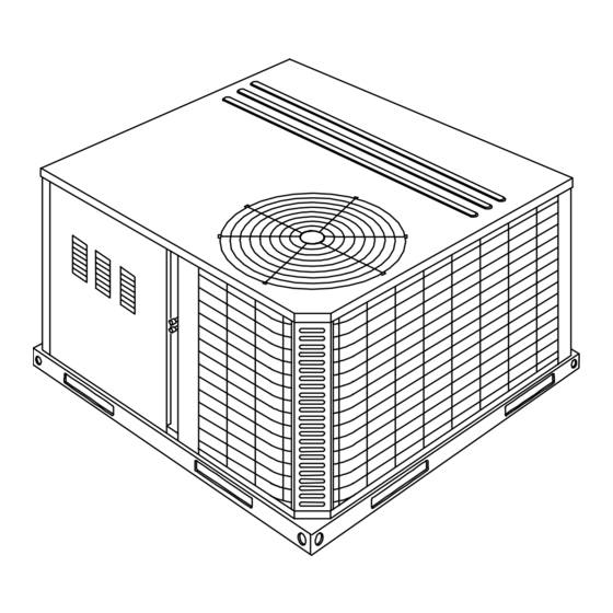
GENERAL
Model DAYA and DBYA units are cooling/heating air conditioners
designed for outdoor installation. Only gas piping, electric power
and duct connections are required at the point of installation.
The gas-fired heaters have hot surface to pilot ignition. The tu-
bular heat exchangers are aluminized steel.
This appliance is not to be used for temporary heating of build-
ings or structures under construction.
INSPECTION
As soon as a unit is received, it should be inspected for possi-
ble damage during transit. If damage is evident, the extent of
the damage should be noted on the carrier's freight bill. A sepa-
rate request for inspection by the carrier's agent should be
made in writing. Refer to Form 50.15-NM for additional infor-
mation.
REPLACEMENT PARTS
• Refer to Replacement Parts, Form 530.46-RP1Y, RP2Y,
RP3Y, RP4Y and RP5Y for Key Replacement Parts.
All forms referenced in this instruction may be ordered from:
APPROVALS
Design certified by CGA and AGA listed as follows:
1. For use as a forced air furnace with cooling unit.
2. For outdoor installation only.
3. For installation directly on combustible flooring or, in U.S.,
on wood flooring or Class A; B; C roof covering material.
4. For installation on combustible material.
5. For use with natural gas and/or propane (LP) gas.
THIS PRODUCT M UST BE INSTALLED IN STRICT COMPLIANCE W ITH
THE ENCLOSED INSTALLATION INSTRUCTIONS AND ANY APPLICABLE
LOCAL, STATE, AND NATIONAL CODES INCLUDING, BUT NOT LIMITED
TO, BUILDING, ELECTRICAL, AND MECHANICAL CODES.
INCORRECT INSTALLATION MAY CREATE A CONDITION WHERE THE
OPERATION OF THE PRODUCT COULD CAUSE PERSONAL INJURY
O R P R O P E R T Y D A M A G E .
035-18267-001 -A-0202
Standard Register
2101 West Tecumseh Rd., Norman, OK 73069
Toll Free Fax: (877) 379-7920
CAUTION
WARNING
Advertisement
Table of Contents
Troubleshooting

Related Manuals for Unitary products group DAYA018


Summary of Contents for Unitary products group DAYA018
-
Page 1: General
SINGLE PACKAGE AIR CONDITIONERS INSTALLATION GAS/ELECTRIC, AIR COOLED INSTRUCTION Supersedes: 035-18267-000 (0801) 035-18267-001 -A-0202 MODELS DAYA018 THRU 048 MODEL DBYA060 1-1/2 THRU 5 TON (10 SEER) GENERAL Model DAYA and DBYA units are cooling/heating air conditioners designed for outdoor installation. Only gas piping, electric power and duct connections are required at the point of installation. -
Page 2: Table Of Contents
FACTORY 042 = 42,000 BTUH YA = 10 SEER Gas Heat / Electric -W = 460-3-60 INSTALLED GAS HEAT 048 = 48,000 BTUH Cool -X = 575-3-60 060 = 60,000 BTUH N = Natural Gas Heat Installed Unitary Products Group... -
Page 3: Limitations
NOTE: Be sure to note supply and return openings. 4. For roof top installation, be sure the structure will support the weight of the unit plus any field installed components. Unit must be installed on a level roof curb or appropriate an- Unitary Products Group... -
Page 4: Roof Curb
See Figure 1. bility of the installer to secure a filter in the return air ductwork or install a Filter/Frame Kit (1FF0110 for the DAYA018 thru POWER AND CONTROL WIRING DAYA042 and 1FF0112 for the DAYA048 and DBYA060). -
Page 5: Compressors
Maximum Capacity of Pipe in Cubic Feet of Gas Per Hour (Based Upon A Pressure Drop Maximum Capacity of Pipe in Thousands of BTU Per Hour (Based Upon A Pressure Drop of 0.3 Inch Water Column and 0.6 Specific Gravity Gas). of 0.5 Inch Water Column). Unitary Products Group... -
Page 6: Flue Vent Hoods
* = Three phase 018 thru 042 size units are supplied with one (1) filter and on three phase 048 and 060 size units two (2) filters are supplied. Single phase units are shipped without filters. See “FILTERS” on page 4. Unitary Products Group... -
Page 7: Unit Weights
= Utilization Range “A” in accordance with ARI Standard 110. = Dual element, time delay type. = If economizer or motorized damper are to be used, 75 VA is required. Refer to price pages for future details. Unitary Products Group... -
Page 8: Dimensions And Clearances
A 1" clearance must be provided between any combustible material and the supply air ductwork. The products of combustion must not be allowed to accumulate within a confined space and recirculate. FIG. 5 - DIMENSIONS AND CLEARANCES Unitary Products Group... -
Page 9: Sequence Of Operation
STOP! Follow “B” in the information on the unit safety label. If you don't smell gas, go to the next step. 1. Check for gas leaks in the unit piping as well as the supply piping. Unitary Products Group... -
Page 10: Manifold Gas Pressure Adjustment
SHUT-OFF VALVE AND SHUT OFF ALL POWER TO THE UNIT. 2. Lift the pilot and sensor from the assembly. Care must be taken not to damage the pilot or sensor when removing this 1. Remove the two (2) #8 screws holding each burner in assembly. place. Unitary Products Group... -
Page 11: Adjustment Of Temperature Rise
Advise him that the flue exhaust hood surface and the immediate area will experience high temperatures during the heating cycle. All unauthorized personnel and debris must be kept away from this area. Unitary Products Group... -
Page 12: Maintenance
If it is not possible to ad- just for the proper flame, the burners may need cleaning. TO CLEAN BURNERS - Remove them from the furnace as ex- plained in “Burner Instructions”. Clean burners with hot water applied along top of the burner. Unitary Products Group... -
Page 13: Superheat Charging Table, 018
D1NA Coil Delta P vs Airflow D1NA024 D1NA042 D1NA048-60 D1NA018 D1NA036 D1NA024-30 D1NA036 D1NA042 D1NA048-60 D1NA018 Linear (D1NA024-30) Linear (D1NA036) Linear (D1NA042) Linear (D1NA048-60) Linear (D1NA018) 1000 1200 1400 1600 1800 2000 2200 Airflow (CFM) Unitary Products Group... -
Page 14: Superheat Charging Table, 042
16.6 18.6 20.6 24.1 27.6 31.1 34.6 11.5 13.6 15.7 17.8 21.7 25.7 29.7 33.7 11.6 13.6 15.6 20.1 24.5 28.9 33.4 11.5 13.5 18.4 23.3 28.2 33.1 11.3 16.7 22.1 27.4 32.8 15.0 20.9 26.7 32.5 Unitary Products Group... -
Page 15: Troubleshooting Chart
24.5 10.9 13.3 15.8 18.2 19.6 21.1 22.5 23.9 10.8 12.9 15.1 17.1 19.1 21.1 23.1 10.1 11.9 14.5 17.1 19.7 22.3 10.0 12.9 15.8 18.7 21.6 11.3 14.5 17.7 20.9 13.2 16.7 20.2 11.8 15.7 19.6 Unitary Products Group... -
Page 16: Troubleshooting
035-18267-001-A-0202 TROUBLESHOOTING NOTE: Before troubleshooting, familiarize yourself with the startup and checkout procedure. Unitary Products Group... -
Page 17: Typical Wiring Diagram, (460-3-60)
(See page 18) M1 - 2 DETAIL "A" DETAIL "A" OPTIONAL CCH S / P CONFIGURATION D / P CONFIGURATION FIG. 9 - TYPICAL WIRING DIAGRAM (208/230-1-60 POWER SUPPLY) FIG. 10 - TYPICAL WIRING DIAGRAM (208/230-3-60 POWER SUPPLY) Unitary Products Group... -
Page 18: Wiring Diagram, Detail "B
035-18267-001-A-0202 (See page 18) FIG. 11 - TYPICAL WIRING DIAGRAM (460-3-60 POWER SUPPLY) (See page 18) FIG. 12 - TYPICAL WIRING DIAGRAM (575-3-60 POWER SUPPLY) Unitary Products Group... - Page 19 035-18267-001-A-0202 TYPICAL WIRING DIAGRAM NOTES (See pages 16 and 17) TYPICAL WIRING DIAGRAM LEGEND (See pages 16 and 17) (ALTERNATE) (ALTERNATE) FIG. 13 - WIRING DIAGRAM DETAIL “B” (460 & 575-3-60 POWER SUPPLY) See page 17 Unitary Products Group...
- Page 20 035-18267-001-A-0202 NOTES Unitary Products Group...
- Page 21 Subject to change without notice. Printed in U.S.A. Copyright by Unitary Products Group 1999. All rights reserved. Supersedes: 035-18267-000-0801 035-18267-000 -A-0202 5005 Interstate Norman Unitary Products Drive Oklahoma Group North 73069...
Need help?
Do you have a question about the DAYA018 and is the answer not in the manual?
Questions and answers