Table of Contents
Advertisement
INSTALLATION
INSTRUCTION
GENERAL INFORMATION .................................... 2
NOMENCLATURE ............................................................... 2
SAFETY ............................................................................... 2
INSPECTION ....................................................................... 2
LIMITATIONS AND LOCATION .................................... 2 & 3
UNIT INSTALLATION ............................................. 3
LOCATION ........................................................................... 3
GROUND INSTALLATION .................................................. 3
ROOF INSTALLATION ........................................................ 3
UNIT PLACEMENT ................................................ 3
TXV KIT INSTALLATION ..................................................... 4
PIPING CONNECTIONS ..................................................... 5
LINE INSTALLATION .......................................................... 5
PRECAUTIONS BRAZING LINES ................................ 5 & 6
TUBE HANGER INSULATION ............................................ 6
UNDERGROUND INSTALLATION ..................................... 6
PRECAUTIONS BRAZING ANGLE VALVE ........................ 6
HEAT PROTECTION ........................................................... 6
CONNECTING REFRIGERANT LINES ....................... 6 & 7
LEAK TEST ......................................................................... 7
ELECTRICAL CONNECTIONS .............................. 7
GENERAL INFORMATION ................................................. 7
GROUNDING ...................................................................... 7
POWER WIRING ................................................................. 7
ACCESSORY WIRING ........................................................ 8
THERMOSTAT MOUNTING/WIRING ................................. 8
DE-HUMIDIFICATION CONTROL ...................................... 8
CONTROL WIRING ............................................................. 8
WIRING DIAGRAMS ................................................... 9 & 10
INDOOR BLOWER SPEED SETTINGS ................. 8
SYSTEM START-UP ............................................ 11
ENERGIZE CRANKCASE HEATER ................................. 11
CHECKING SYSTEM CHARGE......................................... 11
SERVICING AND VERIFY ................................................ 11
RECORDING TOTAL SYSTEM CHARGE ........................ 12
SYSTEM FUNCTIONS ......................................... 12
COMPRESSOR MODES ................................................... 12
DEHUMIDIFICATION ........................................................ 12
COOLING OPERATION ............................................ 12 & 13
SYSTEM CONTROL BOARD FUNCTIONS ...................... 13
INSTRUCTING THE OWNER .............................. 14
INDICATIONS OF PROPER OPERATION ....................... 14
MAINTENANCE ................................................................. 14
CAUTION: READ ALL SAFETY GUIDES BEFORE
YOU BEGIN TO INSTALL YOUR UNIT.
SAVE THIS MANUAL
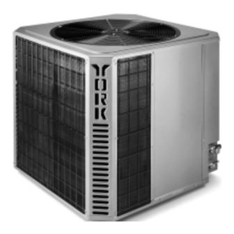
STEALTH
16 SEER 2 TO 5 TON
AIR CONDITIONING UNIT
SPLIT-SYSTEM COOLING
MODELS: H4TS024
H4TS030
H4TS036
H4TS048
H4TS060
035-14511-000 REV B (1299)
Advertisement
Table of Contents

Related Manuals for Unitary products group H4TS024


Summary of Contents for Unitary products group H4TS024
-
Page 1: Table Of Contents
CHECKING SYSTEM CHARGE......... 11 SERVICING AND VERIFY ..........11 RECORDING TOTAL SYSTEM CHARGE ......12 SYSTEM FUNCTIONS ......... 12 COMPRESSOR MODES ........... 12 MODELS: H4TS024 DEHUMIDIFICATION ............12 H4TS030 COOLING OPERATION ..........12 & 13 SYSTEM CONTROL BOARD FUNCTIONS ...... 13 H4TS036 INSTRUCTING THE OWNER ...... -
Page 2: Contents General Information
NOTES are intended to clarify or make the installation easier. operate with any type of low ambient kit. Indoor evaporator coil orifice must be removed prior to CAUTIONS are given to prevent equipment damage. the installation of a factory supplied balanced port TXV kit. Unitary Products Group... -
Page 3: Unit Installation
Make a hole(s) in the structure wall large enough to Isolate the unit from rain gutters to avoid any possible wash accommodate the insulated vapor line, the liquid line and out of the foundation. the wiring. Unitary Products Group... -
Page 4: Txv Kit Installation
After orifice is removed, install the thermal expansion If bulb installation is made on a vertical run, the bulb valve to the orifice distributor assembly with supplied fit- should be located at least 16 inches from any bend, Unitary Products Group... -
Page 5: Piping Connections
Only a small flow is neces- Pack fiber glass insulation and a sealing material such sary to displace air and prevent oxidation. as permagum around refrigerant lines where they pen- etrate a wall to reduce vibration and to retain some flexibility. Unitary Products Group... -
Page 6: Tube Hanger Insulation
DO NOT OVERTIGHTEN (between 40 and 60 inch - lbs. maximum). FIGURE 5 : HEAT PROTECTION NOTE: Do not use the system refrigerant in the outdoor unit to purge or leak test. Unitary Products Group... -
Page 7: Leak Test
FIGURE 6 : TYPICAL FIELD WIRING Power wiring, control (low voltage) wiring, disconnect switches and over current protection to be supplied by the installer. Wire size should be sized per NEC requirements. Unitary Products Group... -
Page 8: Accessory Wiring
325 cfm/ton be sup- too high, unsatisfactory dehumidifaction may occur on first plied at all times. stage operation. To correct for unsatisfactory dehumidifica- tion, add a dehumidistat per figures 8 or 9. Unitary Products Group... -
Page 9: Wiring Diagrams
I N D I C A T O R O N L Y , C A P T H I S W I R E I F N O T U S E D . O N H U M I D I T Y R I S E . FIGURE 8 : FIELD WIRING: H*TS WITH N-AH, F*RP/F*FP, F*RC/F*FC MODELS AND 2-SPEED FAN KIT Unitary Products Group... - Page 10 L I G H T I N D I C A T O R O N L Y , C A P T H I S W I R E O N H U M I D I T Y R I S E I F N O T U S E D . FIGURE 10: TYPICAL FIELD WIRING: H*TS WITH P*DU/P*DD/P*XU 2-STAGE FURNACE Unitary Products Group...
-
Page 11: System Start-Up
H*TS036 and 20+/-3°F for all other models. Add charge if the calculated subcooling temperature TC in step 6 is lower than the recommended level. Remove and recover the refrig- erant if the subcooling TS are higher than the recommended level. Unitary Products Group... -
Page 12: Recording Total System Charge
The operating time for will switch the control circuit and five seconds later will ener- first stage will be slightly longer than with a single speed com- gize the contactor starting the outdoor fan and the compres- Unitary Products Group... -
Page 13: System Control Board Functions
Additionally, during the five second switching from first to second stage, the ™ blower ramp up is delayed. FIGURE 11 : COMFORT ENHANCER CONTROL BOARD Unitary Products Group... -
Page 14: Instructing The Owner
THE OWNER'S APPROVAL. not attempt to start the unit until 8 hours after the switch has been connected. This will allow sufficient time for all liquid refrigerant to be driven out of the compressor. Unitary Products Group... - Page 15 ® 035-14511-000 REV B (1299) NOTES: Unitary Products Group...
- Page 16 H e a t i n g a n d A i r C o n d i t i o n i n g Unitary Products Group 5005 York Drive, Norman, Oklahoma 73069 Subject to change without notice. Printed in U.S.A. 035-14511-000 REV B (1299) Copyright © by Unitary Products Group 1999. All rights reserved. Supersedes: 550.37-N4Y (1299)
Need help?
Do you have a question about the H4TS024 and is the answer not in the manual?
Questions and answers