
Related Manuals for Vertiv Liebert CRV300


Summary of Contents for Vertiv Liebert CRV300
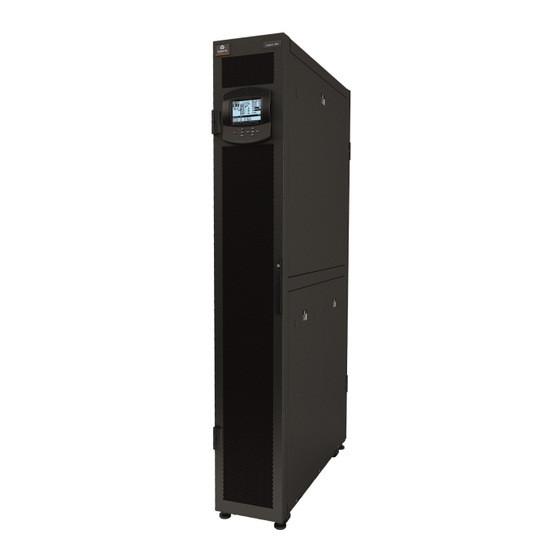
- Page 1 Liebert® CRV300 11-20 kW DX version; 38-60kW CW version A/C Versions Product Documentation English , Cod. 265086, rev. 11.01.2018...
-
Page 3: Table Of Contents
Contents Contents Product Description Application of Liebert CRV Liebert CRV Operation Microprocessor Controls Specifications Heat Rejections Installation drawings Refrigerant, Hydraulic and Electrical Connections Refrigeration & Hydraulic Circuits The product conforms to European Union directives 2006/42/EC; 2014/30/EU; 2014/35/EU; 2014/68/EU. Units are supplied complete with a test certificate and conformity declaration and control component list. -
Page 4: Product Description
Product Description 1.1 Product Description The Liebert CRV is an air cooled full-featured direct expansion and chilled water Thermal Management ® unit to be installed within a row of high density computing racks in a “hot-aisle-cold-aisle” configuration. Air heated by the room equipment enters the unit from the hot aisle; it is filtered, cooled, conditioned, and subsequently returned to the cold aisle. - Page 5 Application of Liebert ® 2.1 First check Before proceeding with Liebert CRV application please make sure the unit selected is suitable for your ® site. Liebert CRV is targeted for small and medium data centers and it is optimized for maximum cool- ®...
- Page 6 Oth- erwise there is a risk of cycling or increased power consumption of both systems, in worst case causing malfunction of the units. For details contact Vertiv sales representative. 2.2 Selection of Liebert CRV unit(s) ®...
- Page 7 Remote Condenser To ensure correct operation, best performance, and longest life the units must be connected to remote condensers approved by Vertiv . The warranty clauses are no longer valid if unit is connected to a not approved remote condenser.
- Page 8 - it is generally advised to distribute the load as much possible uni- formly across the rack height. For more details refer to following details or contact Vertiv Sales Representative. 2.4.1 Single Row Placement The Liebert CRV can be placed either at the end of a row or in between server racks.
- Page 9 Application of Liebert ® Fig. 2c Liebert CRV – Two Rows Placement ® Hot Return Air – Hot Aisle Rack Rack Rack Rack Rack Rack Cold Supply Air – Cold Aisle Rack Rack Rack Rack Rack Rack Hot Return Air – Hot Aisle Cooling unit location within a row becomes less critical when deployed in SmartAisle™...
- Page 10 Application of Liebert ® Fig. 2e Simulated aisle containment using room barriers - multiple rows Hot Return Air Rack Rack Rack Rack Cold Supply Rack Rack Rack Rack Hot Return Air 2.4.3 Liebert CRV Applied in SmartAisle™ Cold Aisle Containment ®...
-
Page 11: Application Of Liebert Crv
Application of Liebert ® 2.5 Temperature sensors The sensor may be placed where desired or left coiled inside the unit. It is recommended that the sen- sor be routed to the front of the heat load for the most accurate temperature reading. In InRow config- uration, the temperature sensor monitors the temperature of the air entering the rack equipment. -
Page 12: Liebert Crv
Liebert CRV 3.1 Standard features Air cooled models DX COOLING COIL It is constructed of copper tubes and hydrophilic coated aluminium fins. The hy- drophilic coating provides superior water carryover resistance. A stainless steel condensate drain pans are provided. REFRIGERATION SYSTEM Single refrigeration circuit includes a liquid line filter drier, a refrigerant sight glass with moisture indicator, an electronic expansion valve, and a liquid line solenoid valve. - Page 13 Liebert CRV LOCKING DISCONNECT SWITCH A molded case circuit interrupter disrupts the flow of power to the unit. The electric panel high voltage compartment can only be accessed with the switch in the ‘off’ po- sition. It is located behind the back door for a quick access. 5 PORT ETHERNET SWITCH The unit is equipped with 5 port Ethernet Switch for connection of the units into LAN to enable team work.
- Page 14 Liebert CRV 3.2 Optional features Air cooled models SUPPLY AIR BAFFLE A field adjustable, modular supply air baffle is located in the discharge air stream. It can be quickly and easily reconfigured to redirect airflow. The angles of the vanes have been optimized to effectively distribute air to heat generating equipment in a wide variety of applications.
- Page 15 Liebert CRV FILTER The optional F5 class (following EN779) filters are two deep pleated 60 mm, located within the cabinet and accessible from the rear of the unit. A filter clog alarm is included as an option. ONE (1) EXTRA COMMON ALARM CONTACT Provides the customer with a total of two sets of nor- mally open (n/o) contacts for remote indication of unit alarms.
-
Page 16: Operation
Operation Unit operation is completely automatic. The below sequence explains how the unit operates: • The air, sucked in by the continuously operating fans, enters the unit. • The air is immediately filtered. • The TEMPERATURE sensor or HUMITEMP (temperature + rel. humidity) sensor (depends on unit configuration), verifies the state of the inlet air, and relays this information to the control system. -
Page 17: Microprocessor Controls
Microprocessor Controls 5.1 iCOM Control Liebert CRV models are controlled by iCOM Medium Board (Fig. 5.a). The control board is housed in the electrical panel and it is connected to the remote display, to be installed in the contain- er/room (connection cable is included). •... - Page 18 Microprocessor Controls 5.2 CDL Graphic Display (option) • Large graphic display (320 x 240 pixels) • Self-explanatory icons are used for the menu-layout of the CDL Display. • Status Report of the latest 400 event-messages of the unit/system. • Graphic Data Records for temperature and humidity, selectable time- frames from 8 minutes to 2 weeks.
-
Page 19: Specifications
Specifications 1.1 Performances - air cooled Tab. 6a - Air cooled Cond. Temp. 45°C CR011RA CR021RA 40°C DB - 20% RH Net Total kW 11.8 20.9 Net Sensible kW 11.8 20.9 Unit Power Input kW 2.99 5.16 Heat rejection kW 14.79 26.06 Supply Air Temperature °C... - Page 20 Specifications Cond. Temp. 45°C CR011RA CR021RA 28°C DB - 45% RH Net Total kW 11.3 19.7 Net Sensible kW 10.7 17.9 Unit Power Input kW 3.57 6.01 Heat rejection kW 14.87 25.71 Supply Air Temperature °C 16.1 14.8 25°C DB - 45% RH Net Total kW 10.7 18.9...
- Page 21 Specifications Tab. 6b - Air cooled CR032RC CR038RC CR060RC 7°C EWT, 10°C EWT, 13°C EWT, 7°C EWT, 10°C EWT, 13°C EWT, 7°C EWT, 10°C EWT, 13°C EWT, 50Hz 5°C Water 5°C Water 5°C Water 5°C Water 5°C Water 5°C Water 5°C Water 5°C Water 5°C Water...
- Page 22 Specifications CR032RC CR038RC CR060RC 7°C EWT, 10°C EWT, 13°C EWT, 7°C EWT, 10°C EWT, 13°C EWT, 7°C EWT, 10°C EWT, 13°C EWT, 50Hz 5°C Water 5°C Water 5°C Water 5°C Water 5°C Water 5°C Water 5°C Water 5°C Water 5°C Water Rise Rise Rise...
- Page 23 Delta without ground or with floating ground • Delta with corner ground • Delta with grounded center tap. If the unit must be installed in the IT System, contact Vertiv Technical department prior to installation. Tab. 6c - Electrical data Unit Power RESIDUAL-CURRENT CIRCUIT Configuration...
- Page 24 Specifications Unit Power RESIDUAL-CURRENT CIRCUIT Configuration Model FLA [A] supply BREAKERS IΔn = 0.3A (400V) (*) CR032RC Cooling CR038RC 230V/1ph/50Hz CR060RC 12.6 CR032RC Cooling + Electrical heating (post 16 A Curve C heating during dehumidification) 400V/3ph+N/50Hz CR038RC 10.7 Fan + electrical heaters CR060RC 10.7 CR032RC...
- Page 25 Specifications 6.3 Sound data Tab. 6d - Liebert CRV Sound Data The following tables show sound levels for every octave band frequency. CR011 Air Cooled Tested Octave band frequency (Hz) Unit SPL Sound Airflow suction Speed Level (2m, f.f., Level 31.5 1000 2000...
-
Page 26: Heat Rejections
Heat Rejections (A version) 7.1 Coupling of Liebert CRV (A-type, 50Hz, CE mark) air condi- tioning units with remote air-cooled condensers (HCR - MCC) HCR and MCC condensers are especially designed to be coupled with the Liebert CRV (A type) air conditioning units power supplied at 50Hz (CE market), within a standard range of external air temperature from -20 °C to +46 °C. - Page 27 Heat Rejections (A version) Tab. 7d - Technical data and performance of air-cooled condenser Liebert HCR Refrigerant Total Heat connections Noise Power Rejection Input Current [mm] Level ** Dimensions Weight Model supply (THR)* Volume Power Absorp tion [dB(A)] @ [mm] [kg] Liquid [V/Ph/Hz]...
- Page 28 Heat Rejections (A version) Tab. 7e - Technical data and performance of air-cooled condenser Liebert HCR 3ph Refrigerant Total Heat connections Noise Power Rejection Input Current [mm] Level ** Dimensions Weight Model supply (THR)* Volume Power Absorp tion [dB(A)] @ [mm] [kg] Liquid...
- Page 29 Heat Rejections (A version) Tab. 7f - Technical data and performance of air-cooled condenser Liebert MC Premium Refrigerant Total Heat connections Noise Power Rejection Input Current [mm] Level ** Dimensions Weight Model supply (THR)* Volume Power Absorp tion [dB(A)] @ [mm] [kg] Liquid...
- Page 30 Heat Rejections (A version) Tab. 7g - Technical data and performance of air-cooled condenser Liebert MC Basic Refrigerant Total Heat connections Noise Power Rejection Input Current [mm] Level ** Dimensions Weight Model supply (THR)* Volume Power Absorp tion [dB(A)] @ [mm] [kg] Liquid...
- Page 31 Heat Rejections (A version) (*) The nominal heat rejection capacities refer to the following operative conditions: • refrigerant R410A • temperature differences: 15 K • (T condensation dew point - Toutdoor). • liquid sub-cooling 3K • height of the installation = 0 m, above the sea level. •...
-
Page 32: Installation Drawings
Installation drawings Fig. 8a Overall dimensions / service area REAR VIEW HOT AIR FRONT VIEW Rear access REAR VIEW diagram COLD TOP VIEW Front access FRONT VIEW diagram with display Fig. 8b Overall dimensions / service area TOP PLENUM FRONT PLENUM 8 - 29 Liebert CRV - PD - 265086 - 11.01.2018... - Page 33 Installation drawings Access required to install the unit between existing racks within the row only Front or Rear clearance required Tab. 8a - Overall dimensions - DX Height Depth Installation depth Weight Models CR11RA 2000 1100 / 1200 1250 CR21RA 2000 1100 / 1200 1250...
- Page 34 Installation drawings Fig. 8c Hole on the raised floor for piping - DX FRONT VIEW UNIT AREA UNIT AREA FRONT VIEW 8 - 31 Liebert CRV - PD - 265086 - 11.01.2018...
- Page 35 Installation drawings Fig. 8d Hole on the raised floor for piping - CW FRONT SIDE OF THE UNIT TOP VIEW FRONT SIDE OF THE UNIT 8 - 32 Liebert CRV - PD - 265086 - 11.01.2018...
- Page 36 Installation drawings Fig. 8e Air bleeding valve position CW ROOF HIDDEN FOR CLARITY DETAIL DETAIL BACK SIDE OF THE UNIT 8 - 33 Liebert CRV - PD - 265086 - 11.01.2018...
- Page 37 Installation drawings Fig. 8f Electrical connections - entry - DX TOP INLET FRONT VIEW BOTTOM INLET 8 - 34 Liebert CRV - PD - 265086 - 11.01.2018...
- Page 38 Installation drawings Fig. 8g Electrical connections - entry - CW TOP INLET 8 - 35 Liebert CRV - PD - 265086 - 11.01.2018...
-
Page 39: Refrigerant, Hydraulic And Electrical Connections
Refrigerant, Hydraulic and Electrical Connections Fig. 9a CR011RA - CR021RA connections DET. B DET. A BOTTOM CONNECTIONS TOP CONNECTIONS 56.9 DET. C 58.5 EC-HVT2 EC-HVT1 EC-LVT1 EC-HVB EC-LVB1 EC-LVT2 EC-LVB2 CR011RA- Unit Top Connection Unit Bottom Connection CR011RA-CR21RA CR21RA OD 12 (Rp ½) Refrigerant liquid line inlet OD 12 (Rp½) CU Refrigerant liquid line inlet ISO 7/1... - Page 40 Refrigerant, Hydraulic and Electrical Connections Fig. 9b CR032RC - CR060RC connections BOTTOM CONNECTIONS TOP CONNECTIONS TOP CHILLED WATER CONNECTIONS 58.2 2.29 1100.0 60.0 EC-LV2B 43.31 2.36 ICWT 40.0 1.57 EC-LV1B 83.0 60.0 3.27 2.36 OCWT 60.0 2.36 60.0 2.36 70.0 90.0 2.76 3.54...
- Page 41 Refrigerant, Hydraulic and Electrical Connections Fig. 9c DX electrical board layout X1/1 X1/1 -X1/2 -X1/2 Wire bridge 9 - 38 Liebert CRV - PD - 265086 - 11.01.2018...
- Page 42 Refrigerant, Hydraulic and Electrical Connections 9.1 DX electrical field connections descriptions - 50 Hz STANDARD ELECTRICAL CONNECTIONS Primary high voltage entrance Quantity (2) 28mm diameter concentric knockouts located in bot- tom of box Secondary high voltage entrance Quantity (2) 35mm diameter concentric knockouts located in top of box Primary low voltage entrance Quantity (1) 18mm diameter knockouts located in bottom of unit Secondary low voltage entrance “...
- Page 43 Refrigerant, Hydraulic and Electrical Connections Fig. 9c CW electrical board layout Wire bridge-Ponte a filo Kabelbrücke-Pont à fil Puente de hilo LEVEL 1 /BOTTTOM/ LEVEL 2 /TOP/ SPRING TERMINALS STTB2,5 9 - 40 Liebert CRV - PD - 265086 - 11.01.2018...
- Page 44 Refrigerant, Hydraulic and Electrical Connections 9.2 CW electrical field connections descriptions - 50 Hz STANDARD ELECTRICAL CONNECTIONS Primary high voltage entrance Quantity (2) 28mm diameter concentric knockouts located in bottom of Secondary high voltage entrance Quantity (2) 35mm diameter concentric knockouts located in top of box Primary low voltage entrance Quantity (1) 18mm diameter knockouts located in bottom of unit Secondary low voltage entrance “...
-
Page 45: Refrigeration & Hydraulic Circuits
Refrigeration & Hydraulic Circuits Fig. 10a Liebert CR011RA - CR021RA (to disconnect for bottom connections) POS. DESCRIPTION POS. DESCRIPTION SHUT-OFF VALVE COMPRESSOR EVAPORATING COIL CRANKCASE HEATER LOW PRESSURE TRANSDUCER HIGH PRESSURE SWITCH LIQUID SEPARATOR AIR COOLED CONDENSER SHUT-OFF SOLENOID VALVE LIQUID RECEIVER HIGH PRESSURE TRANSDUCER ACCESS VALVE 5/16”... - Page 46 Refrigeration & Hydraulic Circuits Fig. 10b Liebert CR032RC - CR060RC CHILLED WATER INLET (top connections) (only with optional 2--- way valve) CHILLED WATER OUTLET (top connections) CHILLED WATER OUTLET (bottom connections) CHILLED WATER INLET (bottom connections) POS. DESCRIPTION Chilled water cooling coil 3 - port water valve Air bleeding valve Valve fittings...
- Page 47 Fabrikant - - Producent Κατασκεναστηζ Vertiv S.r.l. - Zona Industriale Tognana Via Leonardo da Vinci, 16/18 - 35028 Piove di Sacco - Padova (Italy) Il Fabbricante dichiara che questo prodotto è conforme alle direttive Europee: The Manufacturer hereby declares that this product conforms to the European Union directives: Der Hersteller erklärt hiermit, dass dieses Produkt den Anforderungen der Europäischen Richtlinien gerecht wird:...
- Page 48 Leonardo Da Vinci 16/18, Zona Industriale Tognana, 35028 Piove di Sacco (PD) Italy, Tel: +39 049 9719 111, Fax: +39 049 5841 257 © 2016 Vertiv Co. All rights reserved. Vertiv, the Vertiv logo and Vertiv Liebert CRV300 are trademarks or registered trademarks of Vertiv Co. All other names and logos referred to are trade names, trademarks or registered trademarks of their respective owners.
Need help?
Do you have a question about the Liebert CRV300 and is the answer not in the manual?
Questions and answers