Advertisement
Installation Guide
D102031X014
November 2016
Introduction
This installation guide provides instructions for installation, startup and
adjustment. To receive a copy of the instruction manual, contact your
local Fisher Sales Office or Sales Representative or view a copy at
www.fisher.com. For further information, refer to Type Y692 Instruction
Manual, form 5347, D102031X012.
PED Categories
This product may be used as a safety accessory with pressure
equipment in the following Pressure Equipment Directive
97/23/EC categories. It may also be used outside of the Pressure
Equipment Directive using Sound Engineering Practice (SEP)
per table below. For information on the current PED revision,
see Bulletin: D103053X012.
PRODUCT SIZE
DN 40 and 50 / 1-1/2 and 2 in.
Specifications
Maximum Inlet and Outlet Pressures
10.4 bar / 150 psig and 1.0 bar / 15 psig
Proof Test Pressure
All Pressure Retaining Components have been proof tested per
Directive 97/23/EC - Annex 1, Section 7.4
Outlet Pressure Ranges
(1)
Light Spring Assembly: 2 to 7 bar / 1 to 3 in. w.c., 7 to 26 mbar /
3 to 11 in. w.c., 16 to 86 mbar / 6.5 in. w.c. to 1.2 psig, 0.05 to
0.1 bar / 0.7 to 2 psig and 0.07 to 0.2 bar / 1 to 3.2 psig
Heavy Spring Assembly: 0.1 to 0.4 bar / 2 to 5.5 psig and
0.3 to 0.5 bar / 4 to 7 psig
Maximum Operating Outlet Pressure to Avoid Internal
Part Damage
(1)
0.21 bar / 3 psig above outlet pressure setting
Temperature Capabilities
(1)
Nitrile (NBR): -29 to 82°C / -20 to 180°F
Fluoroelastomer (FKM): 5 to 149°C / 40 to 300°F
Installation
▲
Only qualified personnel should install or service a
regulator. Regulators should be installed, operated
and maintained in accordance with international
and applicable codes and regulations, and
Fisher™ instructions.
If the regulator vents fluid or a leak develops in the
system, it indicates that service is required. Failure
to take the regulator out of service immediately may
create a hazardous condition.
Personal injury, equipment damage or leakage due
to escaping fluid or bursting of pressure-containing
parts may result if this regulator is overpressured
or is installed where service conditions could
exceed the limits given in the Specifications section
or where conditions exceed any ratings of the
adjacent piping or piping connections.
1. The pressure/temperature limits in this Installation Guide and any applicable standard or code limitation should not be exceeded.
CATEGORIES
FLUID TYPE
I
(1)
WARNING
To avoid such injury or damage, provide pressure-
relieving or pressure-limiting devices (as required
by the appropriate code, regulation or standard) to
prevent service conditions from exceeding limits.
Additionally, physical damage to the regulator could
result in personal injury and property damage due
to escaping fluid. To avoid such injury and damage,
install the regulator in a safe location.
Clean out all pipelines before installation of the regulator and check to
be sure the regulator has not been damaged or has collected foreign
material during shipping. For NPT bodies, apply pipe compound to
the male pipe threads. For flanged bodies, use suitable line gaskets
and approved piping and bolting practices. Install the regulator in any
position desired, unless otherwise specified, but be sure flow through
the body is in the direction indicated by the arrow on the body.
For proper operation, the regulator must be installed with the spring
1
case barrel pointed down.
It is important that the regulator be installed so that
the vent hole in the spring case is unobstructed at
all times. For outdoor installations, the regulator
should be located away from vehicular traffic and
positioned so that water, ice, and other foreign
materials cannot enter the spring case through the
vent. Avoid placing the regulator beneath eaves or
downspouts, and be sure it is above the probable
snow level.
Overpressure Protection
The recommended pressure limitations are stamped on the regulator
nameplate. Some type of overpressure protection is needed if the
actual inlet pressure exceeds the maximum operating outlet pressure
rating. Overpressure protection should also be provided if the
regulator inlet pressure is greater than the safe working pressure of
the downstream equipment.
Regulator operation below the maximum pressure limitations does
not preclude the possibility of damage from external sources or debris
in the line. The regulator should be inspected for damage after any
overpressure condition.
Startup
The regulator is factory set at approximately the midpoint of the spring
range or the pressure requested, so an initial adjustment may be
required to give the desired results. With proper installation completed
and relief valves properly adjusted, slowly open the upstream and
downstream shutoff valves.
Adjustment
To change the outlet pressure, remove the closing cap or loosen the
locknut and turn the adjusting screw clockwise to increase outlet pressure
or counterclockwise to decrease pressure. Monitor the outlet pressure with
a test gauge during the adjustment. Replace the closing cap or tighten the
locknut to maintain the desired setting.
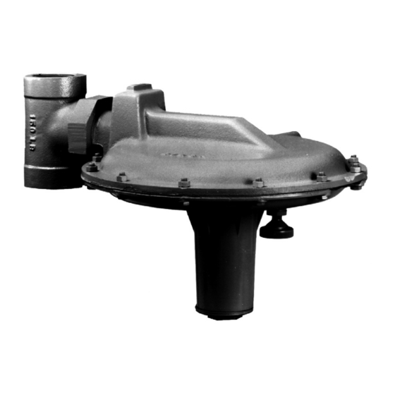
Type Y692
Note
Advertisement
Table of Contents

Related Manuals for Emerson Fisher Y692


Summary of Contents for Emerson Fisher Y692
- Page 1 Installation Guide Type Y692 D102031X014 November 2016 Introduction To avoid such injury or damage, provide pressure- relieving or pressure-limiting devices (as required This installation guide provides instructions for installation, startup and by the appropriate code, regulation or standard) to adjustment. To receive a copy of the instruction manual, contact your prevent service conditions from exceeding limits.
- Page 2 Technologies, Inc. All rights reserved. 10/21. McKinney, Texas 75070 USA Singapore 128461, Singapore The Emerson logo is a trademark and service mark of Emerson Electric Co. All other marks are the property of their prospective owners. T +1 800 558 5853 T +65 6777 8211 Fisher™...
Need help?
Do you have a question about the Fisher Y692 and is the answer not in the manual?
Questions and answers