Advertisement
Quick Links
Installation Guide
D102021X014
English – March 2015
Introduction
This installation guide provides instructions for
installation, startup and adjustment. To receive a copy of
the instruction manual, contact your local Sales Office or
view a copy at www.fisher.com. For further information
refer to: Type Y693 Instruction Manual, D102021X012.
PED Categories
This product may be used as a safety accessory
with pressure equipment in the following Pressure
Equipment Directive categories. It may also be
used outside of the Pressure Equipment Directive
using sound engineering practice (SEP) per table
below. For information on the current PED revision see
Bulletin: D103053X012.
PRODUCT SIZE
DN 40 and 50 / NPS 1-1/2 and 2
Specifications
Body Sizes and End Connection Styles
NPS 1-1/2 and 2 NPT, CL150 and CL300 RF
(Optional) or EN PN 16, 25 and 40 RF (Optional)
Maximum Allowable Inlet Pressure
10.3 bar / 150 psig or body rating limit
Maximum Outlet (Casing) Pressure
1.0 bar / 15 psig
Proof Test Pressure
All Pressure Retaining Components have been
proof tested per Directive.
Outlet (Control) Pressure Ranges
See Table 1
Maximum Operating Outlet Pressure to Avoid
Internal Part Damage
(1)
0.14 bar / 2 psig above outlet pressure setting
Temperature Capabilities
Nitrile (NBR): -29 to 82°C / -20 to 180°F
Fluorocarbon (FKM): 4 to 149°C / 40 to 300°F
Polytetrafluoroethylene (PTFE): -18 to 149°C /
0 to 300°F
Installation
▲
Only qualified personnel shall install
or service a regulator. Regulators
should be installed, operated and
maintained in accordance with
international and applicable codes
1. The pressure/temperature limits in this Installation Guide and any applicable standard or code limitation should not be exceeded.
2. Flanged end connections and end connections for other than U.S. standard can usually be provided; consult the local Sales Office.
CATEGORIES
FLUID TYPE
I
1
(2)
(1)
(1)
(1)
WARNING
and regulations and Emerson Process
Management Regulator Technologies,
Inc. instructions.
If the regulator vents fluid or a leak
develops in the system, it indicates that
service is required. Failure to take the
regulator out of service immediately
may create a hazardous condition.
Personal injury, equipment damage or
leakage due to escaping fluid or bursting
of pressure containing parts may result
if this regulator is overpressured or
is installed where service conditions
could exceed the limits given in the
Specifications section, or where
conditions exceed any ratings of the
adjacent piping or piping connections.
To avoid such injury or damage, provide
pressure-relieving or pressure-limiting
devices (as required by the appropriate
code, regulation or standard) to prevent
service conditions from exceeding limits.
Additionally, physical damage to the
regulator could result in personal injury
and property damage due to escaping
fluid. To avoid such injury and damage,
install the regulator in a safe location.
Clean out all pipelines before installation of the
regulator and check to be sure the regulator has not
been damaged or has collected foreign material during
shipping. For NPT bodies, apply pipe compound to
the external pipe threads. For flanged bodies, use
suitable line gaskets and approved piping and bolting
practices. Install the regulator in any position desired,
unless otherwise specified, but be sure flow through
the body is in the direction indicated by the arrow on
the body.
It is important that the regulator be
installed so that the vent hole in the
spring case is unobstructed at all times.
For outdoor installations, the regulator
should be located away from vehicular
traffic and positioned so that water, ice
and other foreign materials cannot enter
the spring case through the vent. Avoid
placing the regulator beneath eaves or
downspouts, and be sure it is above the
probable snow level.
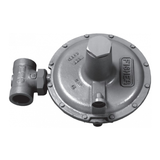
Type Y693
Note
Advertisement

Related Manuals for Emerson Fisher Y693


Summary of Contents for Emerson Fisher Y693
- Page 1 Installation Guide Type Y693 D102021X014 English – March 2015 Introduction and regulations and Emerson Process Management Regulator Technologies, This installation guide provides instructions for Inc. instructions. installation, startup and adjustment. To receive a copy of If the regulator vents fluid or a leak...
-
Page 2: Overpressure Protection
Type Y693 Table 1. Outlet (Control) Pressure Ranges OUTLET PRESSURE RANGE CONTROL SPRING WIRE DIAMETER COLOR CODE psig 1 to 5 mbar 0.5 to 2.0 in. w.c. Brown 2.77 0.109 5 to 12 mbar 2 to 5 in. w.c. 3.05 0.120 Light diaphragm plate 12 to 20 mbar... - Page 3 Type Y693 34B4869-A 34B4867-A ONLY USED WITH THE FOLLOWING ONLY USED WITH THE FOLLOWING CONTROL SPRINGS: CONTROL SPRINGS: BROWN—1 to 5 mbar / 0.5 to 2 in. w.c. DARK BLUE—69 to 138 mbar / 1 to 2 psig RED—5 to 12 mbar / 2 to 5 in. w.c. ORANGE—103 to 228 mbar / 1.5 to 3.3 psig BLACK—12 to 20 mbar / 5 to 8 in.
- Page 4 Type Y693 VIEW B APPLY LUBRICANT 54B2264-B SECTION Figure 2. Type Y693 Regulator, Aluminum Lower Casing Version...
- Page 5 Type Y693 CONTROL LINE CONNECTION SECTION VIEW B APPLY LUBRICANT 54B2266-B Figure 3. Type Y693 Regulator, Steel or Stainless Steel Lower Casing Version...
- Page 6 D102021X014 © 2002, 2019 Emerson Process Management Regulator Technologies, Inc. All rights reserved. 01/19. Americas Asia Pacific The Emerson logo is a trademark and service mark of Emerson Electric McKinney, Texas 75070 USA Singapore 128461, Singapore Co. All other marks are the property of their prospective owners.
Need help?
Do you have a question about the Fisher Y693 and is the answer not in the manual?
Questions and answers