Table of Contents
Advertisement
Quick Links
Instruction Manual
Form 5312
January 2002
Type Y696 Vapor Recovery Regulator
Introduction
Scope of Manual
This instruction manual includes installation, startup,
maintenance, and parts information for the Type Y696
vapor recovery regulator.
Product Description
The Type Y696 vapor recovery regulator is a direct-
operated regulator with internal registration requiring no
downstream control line. It is used to sense increase in
vessel pressure and vent excessive internal vessel
pressure to an appropriate vapor recovery disposal or
reclamations system.
Specifications
The Specifications section lists maximum pressures,
temperatures, and other specifications. Specifications
for a given regulator as it originally comes from the
factory are stamped on the spring case nameplate.
Principle of Operation
The Type Y696 is used to maintain a constant inlet
(blanket) pressure with the outlet flowing to a system
whose pressure is lower than that at the inlet.
When vessel pressure increases above the set point of
the regulator due to pumping in or thermal heating, the
force of the control spring is overcome by pressure
acting on the diaphragm. This moves the disk away
from the orifice allowing gas to flow from the vessel to
the vapor recovery system.
As vessel pressure is reduced, the force of the control
spring causes the disk to move toward the orifice decreas-
ing the flow of gas out of the vessel. As vessel pressure
drops below the set point of the regulator, the disk will seat
against the orifice shutting off the flow of gas.
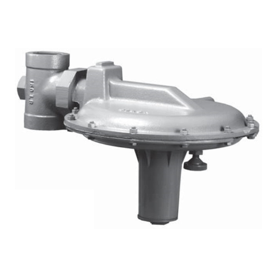
W5996
Figure 1. Type 696 Vapor Recovery Regulator
Installation
Personal injury, equipment damage, or
leakage due to escaping accumulated
gas or bursting of pressure-containing
parts may result if the vapor recovery
regulator is overpressured or installed
where service conditions could exceed
the limits given in the Specifications
section, or where conditions exceed any
ratings of the adjacent piping or piping
connections. To avoid such injury or
damage, provide pressure-relieving or
pressure-limiting devices to prevent
service conditions from exceeding those
limits.
Additionally, physical damage to the
vapor recovery regulator could result in
personal injury and property damage
due to escaping accumulated gas. To
avoid such injury and damage, install
the vapor recovery regulator in a safe
and well ventilated location.
www.FISHERregulators.com
Type Y696
Advertisement
Table of Contents

Related Manuals for Emerson Fisher Y696


Summary of Contents for Emerson Fisher Y696
- Page 1 Type Y696 Instruction Manual Form 5312 January 2002 Type Y696 Vapor Recovery Regulator Introduction Scope of Manual This instruction manual includes installation, startup, maintenance, and parts information for the Type Y696 vapor recovery regulator. Product Description The Type Y696 vapor recovery regulator is a direct- W5996 operated regulator with internal registration requiring no downstream control line.
-
Page 2: Specifications
Type Y696 Specifications Pressure Registration Body Size and End Connection Style Internal See table 1 Maximum Allowable Inlet and Outlet Pressure Spring Case and Vent Connections 15 psig (1,0 bar) 1/4-inch NPT Maximum Temperature Capabilities Outlet Pressure Ranges See table 2 Nitrile (NBR): –20°... -
Page 3: Startup And Adjustment
Type Y696 chemicals, or other foreign material, point the vent down or otherwise protect it. 4. To remotely vent the regulator, remove the vent (key 56) and install obstruction-free tubing or piping into the 1/4-inch NPT vent tapping. Provide protection on a remote vent by installing a screened vent cap into the remote end of the vent pipe. -
Page 4: Maintenance
Type Y696 the spring and diaphragm in the Maintenance section. 1. To inspect and replace the disk assembly (key 25) To adjust the pressure setting, perform the following or orifice (key 27), remove the body cap assembly steps (key numbers are referenced in figure 4): (key 38). -
Page 5: Parts Ordering
Type Y696 2. Remove the adjusting screw (key 2) and the upper 12. Install the assembled parts in the lower casing spring seat (key 44) and change the control spring to (key 20). Make sure that the lever (key 9) fits in the match the desired spring range. - Page 6 Type Y696 Description Part Number Description Part Number Diaphragm Plate Gasket, composition 1A348704022 Body Pusher Post, stainless steel (NACE) 0Y096435072 NPT Screwed Lever Assembly Cast iron Stainless steel 1E3409000B2 1-1/2-inch size 1B403419012 Stainless steel (NACE) 1E3409X0012 2-inch size 1B403519012 Machine Screw (2 required) Steel Stainless steel 1A866935032...
- Page 7 Type Y696 SECTION A-A 43B0679 Figure 4. Type Y696 Assembly...
- Page 8 Type Y696 Fisher is a mark owned by Fisher Controls International, Inc., a business of Emerson Process Management. The Emerson logo is a trademark and service mark of Emerson Electric Co. All other marks are the property of their respective owners.
Need help?
Do you have a question about the Fisher Y696 and is the answer not in the manual?
Questions and answers