Advertisement
RGB CONTROLLER
ZN1DI-RGBX4
FEATURES
Control of RGBW LED or 4 independent channels.
External power supply required (12 or 24 VDC).
LED test function.
Integrated KNX BCU.
Conformity with the CE directives.
1. KNX
2. KNX programming and
connector
internal test LED
4. Test button 5. LED control
terminal block
KNX programming button: short button press to set the programming mode. If this button is held while plugging the device to
the KNX bus, it enters into safe mode.
KNX programming and internal test LED: the red LED indicates programming mode. When the device goes into safe mode, it
blinks red every 0.5 seconds. The blinking blue LED indicates internal test.
Test button: it tests the functioning of channels connected to the device. Push and hold for 3 seconds to get in/out of the testing
mode.
Test LED and polarity: tricolored LED that indicates which channel (red=channel 1/R, green=channel 2/G, blue=channel 3/B,
qhite=channel 4/W) is being tested. Orange light indicates reverse polarity in external power supply.
GENERAL SPECIFICATIONS
Type of device
Voltage (typical)
Voltage range
KNX supply
Power consumption
Connection type
External power supply
Power supply cable section
Type of control
Operation temperature
Storage temperature
Operation humidity
Storage humidity
Complementary characteristics
Protection class
Operation type
Device action type
Electrical stress period
Protection degree
Installation
Response on KNX bus failure
Response on KNX bus restart
PCB CTI index
Housing material
Dimensions
Weight
Operation indication
© Zennio Avance y Tecnología S.L.
3. KNX programming
button
6. External
7. Test and reversed
power supply
polarity indicator LED
Electric operation control device
29VDC
21...31VDC
145mW
Typical bus connector TP1, 0.80mm2 section
12 or 24VDC
1.5 mm² to 2.5 mm²
PWM (150, 300, 488 or 600 Hz)
0ºC to +45ºC
-5ºC to +50ºC
30 to 85% RH (no condensation)
30 to 85% RH (no condensation)
Class B
II
Continuous operation
Type 1
Long
IP20, clean environment
Surface mounted independent device
Connect LUMENTO as near as possible to both, the LED to dimmer and the external power supply
Data saving
Data recovery
175V
PC-ABS FR V0 halogen free
Without terminal blocks: 144x44x22mm / With terminal blocks: 157x44x22mm
104g
Programming/internal test LED indicates: programming mode (red lighting), safe mode (red
blinking) and internal test (blue blinking).
Test LED indicates: white, test channel 4 (W); red, test channel 1 (R); green, test channel 2 (G);
blue, test channel 3 (B). Reverse polarity of external power supply is indicated by the test LED with
orange light.
Edition 4
3
1
For further information
www.zennio.com
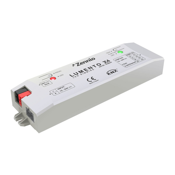
LUMENTO X4
LED DIMMING
Technical Documentation
5
4
7
2
Figure 1. LUMENTO X4
6
Page. 1 of 2
Advertisement
Table of Contents

Subscribe to Our Youtube Channel
Related Manuals for Zennio ZN1DI-RGBX4


Summary of Contents for Zennio ZN1DI-RGBX4
- Page 1 Test LED indicates: white, test channel 4 (W); red, test channel 1 (R); green, test channel 2 (G); blue, test channel 3 (B). Reverse polarity of external power supply is indicated by the test LED with orange light. Page. 1 of 2 © Zennio Avance y Tecnología S.L. Edition 4 For further information www.zennio.com...
- Page 2 The WEEE logo means that this device contains electronic parts and it must be properly disposed of by following the instructions at http://zennio.com/weee-regulation. Page. 2 of 2 © Zennio Avance y Tecnología S.L. Edition 4 For further information www.zennio.com...
Need help?
Do you have a question about the ZN1DI-RGBX4 and is the answer not in the manual?
Questions and answers