Chapters
Table of Contents

Subscribe to Our Youtube Channel
Related Manuals for WIKA TR57-M


Summary of Contents for WIKA TR57-M
- Page 1 Operating instructions Betriebsanleitung Pipe surface resistance thermometer Miniature design, model TR57-M Rohroberflächen-Widerstandsthermometer Miniaturausführung, Typ TR57-M Model TR57-M...
- Page 2 3 - 26 Betriebsanleitung Typ TR57-M Seite 27 - 50 Further languages can be found at www.wika.com. © 03/2017 WIKA Alexander Wiegand SE & Co. KG All rights reserved. / Alle Rechte vorbehalten. WIKA ® is a registered trademark in various countries.
-
Page 3: Table Of Contents
2. Design and function 3. Safety 4. Transport, packaging and storage 5. Commissioning, operation 6. Faults 7. Maintenance, cleaning and calibration 8. Dismounting, return and disposal 9. Specifications Declarations of conformity can be found online at www.wika.com. WIKA operating instructions model TR57-M... -
Page 4: General Information
Skilled personnel must have carefully read and understood the ■ operating instructions prior to beginning any work. Subject to technical modifications. ■ Further information: ■ - Internet address: www.wika.de / www.wika.com - Application consultant: Tel.: +49 9372 132-0 Fax: +49 9372 132-406 info@wika.de WIKA operating instructions model TR57-M... -
Page 5: Design And Function
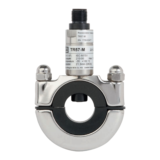
Process connection 2.2 Description The model TR57-M pipe surface resistance thermometer consists of a temperature probe and a clamping fixture (pipe adapter). Any change in the temperature causes a change in the resistance of the sensor in the temperature probe. This change can be measured directly or can, optionally, be converted via a temperature transmitter into a 4 ... - Page 6 With transmitter Process temperature range -20 ... +100 °C [-4 ... +212 °F], max. 150 °C [302 °F] for 30 min. Without transmitter Process temperature range -20 ... +150 °C [-4 ... +302 °F] M12x1 M12x1 SW18 WIKA operating instructions model TR57-M...
- Page 7 81 [3.19] (ISO 1127) 50.8 2" DIN 11866 row C / 92 [3.62] 14 [0.55] 18.5 [0.73] 81 [3.19] ASME BPE 52.0 DN 50 EN 10357 series B 92 [3.62] 14 [0.55] 18.5 [0.73] 81 [3.19] WIKA operating instructions model TR57-M...
-
Page 8: Safety
... indicates a potentially dangerous situation that can result in serious injury or death, if not avoided. CAUTION! ... indicates a potentially dangerous situation that can result in light injuries or damage to equipment or the environment, if not avoided. WIKA operating instructions model TR57-M... - Page 9 Improper handling or operation of the instrument outside of its technical specifications requires the instrument to be taken out of service immediately and inspected by an authorised WIKA service engineer. The manufacturer shall not be liable for claims of any type based on operation contrary to the intended use.
- Page 10 Operating personnel The personnel trained by the operator are understood to be personnel who, based on their education, knowledge and experience, are capable of carrying out the work described and independently recognising potential hazards. WIKA operating instructions model TR57-M...
- Page 11 Process temperature -20 ... +150 °C Process diameter 13.0 mmm (DN 10) or 12.7 mm (1/2”) WIKA Alexander Wiegand SE & Co. KG D-63911 Klingenberg Made in Germany 2017-02 Product label for measuring insert Replaceable measuring insert TR57-M ...
-
Page 12: Transport, Packaging And Storage
1. Place the instrument, along with shock-absorbent material, in the packaging. 2. If stored for a prolonged period of time (more than 30 days), place a bag containing a desiccant inside the packaging. WIKA operating instructions model TR57-M... -
Page 13: Commissioning, Operation
-20 ... +150 °C [-4 ... +302 °F] 5.1 Mounting The model TR57-M pipe surface resistance thermometer consists of a temperature probe (measuring insert) and a clamping fixture (pipe adapter). The pipe adapter is available in four sizes and is adapted to the process-side pipe diameter (DN 10 ... - Page 14 Ideal mounting position, so long as no air bubble formation occurs. Risky mounting position, since the increased heating of the pipe and the connection flange can lead to a falsification of the measuring result. WIKA operating instructions model TR57-M...
- Page 15 5.2 Electrical connection Depending on the type of application, the electrical connection must be protected from mechanical damage. The electrical connection is made via an M12 x 1 circular connector (4-pin). Output signal Pt100 ■ WIKA operating instructions model TR57-M...
- Page 16 AC 50 V or DC 120 V. Preferably, a connection to an SELV or PELV circuit is recommended; alternatively protective measures from HD 60346-4-41 (DIN VDE 0100-410). WIKA operating instructions model TR57-M...
- Page 17 22 mA. Medium temperature outside the span ■ If the medium temperature exceeds that configured within the transmitter, the transmitter will operate in a linear fashion within the following limits: 3.7 mA (MRS); 22 mA (MRE). WIKA operating instructions model TR57-M...
-
Page 18: Faults
Faults Causes Measures No signal/cable Mechanical load too high or Replace the probe with a suitable break overtemperature version Erroneous measured Sensor drift caused by Replace the probe with a suitable values overtemperature version WIKA operating instructions model TR57-M... -
Page 19: Maintenance, Cleaning And Calibration
7.1 Maintenance The resistance thermometers described here require absolutely no maintenance and contain no components which could be repaired or replaced. Repairs must only be carried out by the manufacturer. WIKA operating instructions model TR57-M... - Page 20 In line with the intended use of a pipe-mounted probe, the testing should be carried out on controlled, heated reference surface (dry calibration). WIKA operating instructions model TR57-M...
-
Page 21: Dismounting, Return And Disposal
Observe the information in the material safety data sheet for the corresponding medium. WARNING! Risk of burns During dismounting there is a risk of dangerously hot surfaces. ▶ Let the instrument cool down sufficiently before dismounting it! WIKA operating instructions model TR57-M... - Page 22 8. Dismounting, return and disposal 8.2 Return Strictly observe the following when shipping the instrument: All instruments delivered to WIKA must be free from any kind of hazardous substances (acids, bases, solutions, etc.) and must therefore be cleaned before being returned.
-
Page 23: Specifications
Measuring element Pt100 (measuring current max. 10 mA, 0.3 ... 1 mA recommended) Temperature at the connector Max. 85 °C [185 °F] Connection method 3-wire Tolerance value of the Class A measuring element per IEC 60751 WIKA operating instructions model TR57-M... - Page 24 For detailed specifications for Pt sensors, see Technical information IN 00.17 at www.wika.com. Readings in % refer to the measuring span Measuring insert Spring Stainless steel 1.4310 Probe insert PEEK Sensor tip 935 silver Circular connector M12 PA / gold-plated contacts Weight 20 g WIKA operating instructions model TR57-M...
- Page 25 European Union EMC directive EN 61326 emission (group 1, class B) and immunity (industrial application) RoHS directive 1) Only for built-in transmitter For further specifications see WIKA data sheet TE 60.57 and the order documentation. WIKA operating instructions model TR57-M...
- Page 26 WIKA operating instructions model TR57-M...
- Page 27 Inhalt Inhalt 1. Allgemeines 2. Aufbau und Funktion 3. Sicherheit 4. Transport, Verpackung und Lagerung 5. Inbetriebnahme, Betrieb 6. Störungen 7. Wartung, Reinigung und Kalibrierung 8. Demontage, Rücksendung und Entsorgung 9. Technische Daten Konformitätserklärungen finden Sie online unter www.wika.de. WIKA-Betriebsanleitung Typ TR57-M...
-
Page 28: Allgemeines
Das Fachpersonal muss die Betriebsanleitung vor Beginn aller Arbei- ■ ten sorgfältig durchgelesen und verstanden haben. Technische Änderungen vorbehalten. ■ Weitere Informationen: ■ - Internet-Adresse: www.wika.de / www.wika.com - Anwendungsberater: Tel.: +49 9372 132-0 Fax: +49 9372 132-406 info@wika.de WIKA-Betriebsanleitung Typ TR57-M... -
Page 29: Aufbau Und Funktion
Prozessanschluss 2.2 Beschreibung Das Rohroberflächen-Widerstandsthermometer Typ TR57-M besteht aus einem Temperaturfühler und einer Klemmvorrichtung (Rohradapter). Eine Temperaturänderung bewirkt eine Änderung des Widerstands- wertes des Sensors im Temperaturfühler. Diese Änderung kann direkt abgegriffen werden oder optional über einen Temperaturtransmitter in ein temperaturproportionales 4 ... - Page 30 Prozesstemperaturbereich -20 ... +150 °C [-4 ... +302 °F] M12x1 M12x1 SW18 Mit Transmitter Prozesstemperaturbereich -20 ... +100 °C [-4 ... +212 °F], max. 150 °C [302 °F] für 30 min Ohne Transmitter Prozesstemperaturbereich -20 ... +150 °C [-4 ... +302 °F] M12x1 M12x1 SW18 WIKA-Betriebsanleitung Typ TR57-M...
- Page 31 14 [0,55] 18,5 [0,73] 81 [3,19] ASME BPE 52,0 DN 50 EN 10357 Serie B 92 [3,62] 14 [0,55] 18,5 [0,73] 81 [3,19] 53,0 DN 50 EN 10357 Serie A 92 [3,62] 14 [0,55] 18,5 [0,73] 81 [3,19] WIKA-Betriebsanleitung Typ TR57-M...
-
Page 32: Sicherheit
Tod oder zu schweren Verletzungen führen kann, wenn sie nicht gemieden wird. VORSICHT! ... weist auf eine möglicherweise gefährliche Situation hin, die zu geringfügigen oder leichten Verletzungen bzw. Sach- und Umweltschäden führen kann, wenn sie nicht gemieden wird. WIKA-Betriebsanleitung Typ TR57-M... - Page 33 ... hebt nützliche Tipps und Empfehlungen sowie Informatio- nen für einen effizienten und störungsfreien Betrieb hervor. 3.2 Bestimmungsgemäße Verwendung Das Widerstandsthermometer Typ TR57-M wird speziell zur Messung von Temperaturen an Rohrleitungen im Bereich von -20 … +150 °C [-4 ... +302 °F].
- Page 34 Normen und Bestimmungen. Das Elektrofachpersonal muss die Bestimmungen der geltenden gesetzlichen Vorschriften zur Unfall- verhütung erfüllen. Bedienpersonal Das vom Betreiber geschulte Personal ist aufgrund seiner Bildung, Kenntnisse und Erfahrungen in der Lage, die beschriebenen Arbeiten auszuführen und mögliche Gefahren selbstständig zu erkennen. WIKA-Betriebsanleitung Typ TR57-M...
- Page 35 130-00 max. 1.0 Nm Process temperature -20 ... +150 °C Process diameter 13.0 mmm (DN 10) or 12.7 mm (1/2”) WIKA Alexander Wiegand SE & Co. KG D-63911 Klingenberg Made in Germany 2017-02 Typenschild für Messeinsatz Replaceable measuring insert TR57-M ...
-
Page 36: Transport, Verpackung Und Lagerung
Bedingungen erfüllt. Wenn die Originalverpackung nicht vorhanden ist, dann das Gerät wie folgt verpacken und lagern: 1. Das Gerät mit dem Dämmmaterial in der Verpackung platzieren. 2. Bei längerer Einlagerung (mehr als 30 Tage) einen Beutel mit Trock- nungsmittel der Verpackung beilegen. WIKA-Betriebsanleitung Typ TR57-M... -
Page 37: Inbetriebnahme, Betrieb
Sonderausführung mit Transmitter: -20 ... +150 °C [-4 ... +302 °F] 5.1 Montage Das Rohroberflächen-Widerstandsthermometer Typ TR57-M besteht aus einem Temperaturfühler (Messeinsatz) und einer Klemmvorrichtung (Rohradapter). Der Rohradapter ist in vier Baugrößen erhältlich und wird über temperaturbeständige Silikoneinlagen an den prozessseitigen Rohrdurchmesser (DN 10 …... - Page 38 Bedenkliche Montageposition, da die aufsteigende Abwärme der Rohre zu einer Verfälschung des Messergebnisses führen kann. Ideale Montageposition, sofern keine Luftblasenbildung erfolgt. Bedenkliche Montageposition, da aufsteigende Abwärme der Rohre und des Verbindungsflansches zu einer Verfälschung des Messer- gebnisses führen können. WIKA-Betriebsanleitung Typ TR57-M...
- Page 39 Anzugsdrehmoment von 0,5 ... 1,0 Nm wählen. 5.2 Elektrischer Anschluss Je nach Art der Anwendung muss der elektrische Anschluss vor mecha- nischen Schäden geschützt werden. Der elektrische Anschluss erfolgt über den Rundstecker M12 x 1 (4-polig). Ausgangssignal Pt100 ■ WIKA-Betriebsanleitung Typ TR57-M...
- Page 40 Netzspannung oder Spannung größer AC 50 V bzw. DC 120 V getrennt sind. Zu bevorzugen ist ein Anschluss an SELV- oder PELV-Stromkreise; alternativ ist eine Schutzmaßnahme aus HD 60346-4-41 (DIN VDE 0100-410) zu empfehlen. WIKA-Betriebsanleitung Typ TR57-M...
- Page 41 Tritt ein interner Gerätefehler auf, erfolgt die Fehlersignalisierung aufsteuernd ca. 22 mA. Medientemperatur außerhalb der Spanne ■ Bei einer Überschreitung der im Transmitter konfigurierten Medien- temperatur läuft der Transmitter noch linear in folgende Grenzen: 3,7 mA (MBA); 22 mA (MBE). WIKA-Betriebsanleitung Typ TR57-M...
-
Page 42: Störungen
Kontaktdaten siehe Kapitel 1 „Allgemeines“ oder Rückseite der Betriebsanleitung. Störungen Ursachen Maßnahmen Kein Signal/Lei- Zu hohe mechanische Belas- Ersatz des Fühlers durch eine tungsbruch tung oder Übertemperatur geeignete Ausführung Fehlerhafte Mess- Sensordrift durch Übertem- Ersatz des Fühlers durch eine werte peratur geeignete Ausführung WIKA-Betriebsanleitung Typ TR57-M... -
Page 43: Wartung, Reinigung Und Kalibrierung
Speisetrennern oder Transmittern 7. Wartung, Reinigung und Kalibrierung Kontaktdaten siehe Kapitel 1 „Allgemeines“ oder Rückseite der Betriebsanleitung. 7.1 Wartung Die hier beschriebenen Widerstandsthermometer sind wartungsfrei und enthalten keinerlei Bauteile, welche repariert oder ausgetauscht werden könnten. Reparaturen sind ausschließlich vom Hersteller durchzuführen. WIKA-Betriebsanleitung Typ TR57-M... - Page 44 24 Monaten zu rekalibrieren. Dieser Zeitraum verringert sich abhän- gig vom Einsatzfall. Die Kalibrierung kann durch den Hersteller sowie mit Kalibriergeräten vor Ort durch qualifiziertes Fachpersonal erfolgen. Entsprechend dem Bestimmungszweck eines Rohranlegefühlers, sollte die Prüfung auf einer kontrolliert beheizten Referenzfläche erfolgen (Trockenkalibrierung). WIKA-Betriebsanleitung Typ TR57-M...
-
Page 45: Demontage, Rücksendung Und Entsorgung
Applikation; Das Thermometer selbst ist prinzipiell ungefährlich). ▶ Angaben im Sicherheitsdatenblatt für den entsprechen- den Messstoff beachten. WARNUNG! Verbrennungsgefahr Beim Ausbau besteht Gefahr durch gefährlich heiße Oberflä- chen. ▶ Vor dem Ausbau das Gerät ausreichend abkühlen lassen! WIKA-Betriebsanleitung Typ TR57-M... - Page 46 8. Demontage, Rücksendung und Entsorgung 8.2 Rücksendung Beim Versand des Gerätes unbedingt beachten: Alle an WIKA gelieferten Geräte müssen frei von Gefahrstoffen (Säuren, Laugen, Lösungen, etc.) sein und sind daher vor der Rücksendung zu reinigen. WARNUNG! Körperverletzungen, Sach- und Umweltschäden durch Messstoffreste Messstoffreste im ausgebauten Gerät können zur Gefähr- dung von Personen, Umwelt und Einrichtung führen.
-
Page 47: Technische Daten
Thermometer mit direktem Sensorausgang mit Pt100 Prozesstemperaturbereich -20 ... +150 °C [-4 ... +302 °F] Messelement Pt100 (Messstrom max. 10 mA, empfohlen 0,3 ... 1 mA) Temperatur am Stecker Max. 85 °C [185 °F] Schaltungsart 3-Leiter Grenzabweichung des Messele- Klasse A mentes nach IEC 60751 WIKA-Betriebsanleitung Typ TR57-M... - Page 48 Detaillierte Angaben zu Pt-Sensoren siehe Technische Information IN 00.17 unter www.wika.de. Angaben in % beziehen sich auf die Messspanne Messeinsatz Feder CrNi-Stahl 1.4310 Fühlereinsatz PEEK Sensorspitze 935er Silber Rundstecker M12 PA / vergoldete Kontakte Gewicht 20 g WIKA-Betriebsanleitung Typ TR57-M...
- Page 49 Silikon HTV/PTFE Zulassungen Logo Beschreibung Region EU-Konformitätserklärung Europäische Union EMV-Richtlinie EN 61326 Emission (Gruppe 1, Klasse B) und Störfestig- keit (industrieller Bereich) RoHS-Richtlinie 1) Nur bei eingebautem Transmitter Weitere technische Daten siehe WIKA-Datenblatt TE 60.57 sowie Bestellunterlagen. WIKA-Betriebsanleitung Typ TR57-M...
- Page 50 WIKA-Betriebsanleitung Typ TR57-M...
- Page 51 WIKA operating instructions model TR57-M...
- Page 52 WIKA subsidiaries worldwide can be found online at www.wika.com. WIKA-Niederlassungen weltweit finden Sie online unter www.wika.de. WIKA Alexander Wiegand SE & Co. KG Alexander-Wiegand-Strasse 30 63911 Klingenberg • Germany Tel. +49 9372 132-0 Fax +49 9372 132-406 info@wika.de www.wika.de WIKA operating instructions model TR57-M...
Need help?
Do you have a question about the TR57-M and is the answer not in the manual?
Questions and answers