Table of Contents
Advertisement
Quick Links
Getting started with the X-NUCLEO-SNK1M1 USB Type-C® Power Delivery Sink
Introduction
The X-NUCLEO-SNK1M1 expansion board allows evaluating the features of TCPP01-M12 and the USB Type-C® overvoltage
protection for V
and CC lines suitable for Sink applications.
BUS
The expansion board is designed to be stacked on top of any STM32 Nucleo-64 development board exploiting the
characteristics of the USB Type-C® and Power Delivery (UCPD) peripheral embedded in their microcontrollers.
It can also be stacked on other STM32 Nucleo development boards not supporting the UCPD peripheral to demonstrate the
USB Type-C® basic operations (attach, detach and power supply current capability recognition).
The X-NUCLEO-SNK1M1 provides an effective demonstration of the dead battery operation, thanks to the integrated
ST715PU33R
LDO linear regulator that supplies the connected
via a USB Type-C® connector.
The X-NUCLEO-SNK1M1 is compliant with the latest USB Type-C® and Power Delivery specifications and is also USB-IF
certified as a 100 W solution supporting Programmable Power Supply (PPS) function.
The companion software package (X-CUBE-TCPP) contains the application examples for development boards embedding
UCPD-based microcontrollers (NUCLEO-G071RB, NUCLEO-G474RE and NUCLEO-G0B1RE) and for non-UCPD ones
(NUCLEO-L412RB-P).
Note:
Before running any demo, set CC1 J1, CC2 J2, JP3 and JP4 jumpers according to the configuration described in
Section 1.3 Demo application
UM2773 - Rev 6 - August 2022
For further information contact your local STMicroelectronics sales office.
expansion board based on TCPP01-M12 for STM32 Nucleo
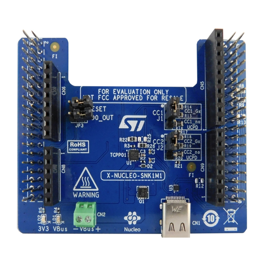
Figure 1.
X-NUCLEO-SNK1M1 expansion board
setup.
STM32 Nucleo development board
UM2773
User manual
when a Source is attached
www.st.com
Advertisement
Table of Contents

Related Manuals for ST X-NUCLEO-SNK1M1


Summary of Contents for ST X-NUCLEO-SNK1M1
- Page 1 Source is attached via a USB Type-C® connector. The X-NUCLEO-SNK1M1 is compliant with the latest USB Type-C® and Power Delivery specifications and is also USB-IF certified as a 100 W solution supporting Programmable Power Supply (PPS) function. The companion software package (X-CUBE-TCPP) contains the application examples for development boards embedding UCPD-based microcontrollers (NUCLEO-G071RB, NUCLEO-G474RE and NUCLEO-G0B1RE) and for non-UCPD ones (NUCLEO-L412RB-P).
-
Page 2: Getting Started
Moreover, two couples of resistances, used as solder bridge selectors, allow exploiting the USB2.0 peripheral. The expansion board must be plugged on the matching pins of the development board CN7 and CN10 ST morpho connectors. When plugged onto an... -
Page 3: Figure 2. X-Nucleo-Snk1M1 Main Functional Blocks (Top View)
UM2773 Hardware architecture Figure 2. X-NUCLEO-SNK1M1 main functional blocks (top view) Morpho connector (CN7) Arduino connector (CN6, CN8) Reset jumper (JP4) LDO OUT jumper (JP3) 3V3 LED (LD2) LED (LD1) Power connector (CN2) TCPP01-M12 USB-C overvoltage protection for VBUS and CC lines (U1) -
Page 4: Usb Type-C® Connector
UM2773 Hardware architecture Figure 3. X-NUCLEO-SNK1M1 main functional blocks (bottom view) Morpho connector (CN10) ESDA25P35-1U1M TVS diode (D1) OVP threshold solder bridges (SH1, SH2, SH3, SH4, SH5) ST715PU33R high input voltage LDO linear regulator (U2) Morpho connector (CN7) 1.2.1 USB Type-C® connector The USB Type-C®... -
Page 5: Tcpp01-M12 Usb Type-C® Protection And V
(left side) and is placed at the board bottom. On the X-NUCLEO-SNK1M1 expansion board, the 22 V OVP threshold is set by default via SH5. To change the threshold to another value (6, 10, 13 or 17 V), remove SH5 and add a different solder bridge on the selected OVP voltage. -
Page 6: Cc Lines And Configuration Jumpers
CC lines and configuration jumpers Two headers for jumpers (J1 and J2) have been integrated to change the CC lines paths from the TCPP01-M12 protection to the ST morpho connectors (CN7 and CN10) on the STM32 Nucleo development board, setting them differently according to the peripheral mapping of the STM32 microcontroller. -
Page 7: Usb 2.0 Data Path And Configuration Setting
STM32 Nucleo development boards that feature a USB2.0 peripheral to expose the D+/D- lines on the USB Type-C® receptacle (CN1). Most STM32 Nucleo-64 development boards feature this functionality on the ST morpho connector CN10-12 and CN10-14 pins, whereas NUCLEO-L412RB-P, NUCLEO-L433RC-P, NUCLEO-L452RE-P NUCLEO-L476RG boards map USB2.0 data pins on CN10-33 and CN10-17 pins. -
Page 8: St Morpho And Arduino Uno V3 Connectors
TCPP01-M12 either via the 3.3 V provided by the STM32 Nucleo development board or via a GPIO on the ST morpho connector (CN7-1). You can select the path through R23 and R24 resistances. This option, combined with the TCPP01-M12 low consumption, is useful for... -
Page 9: Dead Battery Mode Configuration Jumpers And Internal Ldo
3.3V CN10 R25 0 N.M. DB_OUT R26 0 To select the dead battery operation mode on the X-NUCLEO-SNK1M1, JP3 and JP4 jumpers must be fit. Table 4. JP3 and JP4 power mode selection jumpers Jumpers Power mode JP3 (LDO_OUT) JP4 (RESET) -
Page 10: Power Connector
3V3 through the R25 mounting solder bridge (consequently, R26 must be not fitted). In the application firmware package, this option has been included in the firmware examples where a GPIO (ST morpho CN10-24) properly drives the dead battery option. - Page 11 Remove the power selection jumper from the JP2 header on NUCLEO-G071RB/NUCLEO-G0B1RE development board (previously set on STLK 1-2 pins) and leave it fully open. Step 4. On the X-NUCLEO-SNK1M1, set LDO OUT jumper (JP3) and NRST jumper (JP4). Step 5. Plug a Source board to X-NUCLEO-SNK1M1 CN1 connector through a USB Type-C®...
- Page 12 (previously set on STLK 1-2 pins) and leave it fully open. Step 4. Set JP8 jumper on 2-3 pins. Step 5. On the X-NUCLEO-SNK1M1, set LDO OUT jumper (JP3) and NRST jumper (JP4). Step 6. Plug a Source board to X-NUCLEO-SNK1M1 CN1 connector through a USB Type-C®...
- Page 13 NUCLEO-L412RB-P development board (previously set on STLK 1-2 pins) and leave it fully open. Step 4. On the X-NUCLEO-SNK1M1, set LDO OUT jumper (JP3) and NRST jumper (JP4). Step 5. Plug a Source board to X-NUCLEO-SNK1M1 CN1 connector through a USB Type-C® cable.
-
Page 14: Schematic Diagrams
Schematic diagrams Figure 12. X-NUCLEO-SNK1M1 circuit schematic (1 of 2) 3.3V CN10 VCC_OUT AVDD BOOT0 DP_Gx_Fx IOREF IOREF AVDD DM_Gx_Fx RESET NRST RESET CC1_G4 D10 FLT_IN +3V3 +3V3 DM_Lx CC1_G0 D7 DB_OUT CC2_G0 CC2_G4 D5 CC1_no_UCPD CC2_no_UCPD 61300811821 61301011821 AGND... -
Page 15: Figure 13. X-Nucleo-Snk1M1 Circuit Schematic (2 Of 2)
Figure 13. X-NUCLEO-SNK1M1 circuit schematic (2 of 2) 3.3V VBUS VBUS STL11N3LLH6 R1_6V 2.7k 0 N.M. 3.9k R1_10V 1.5k 0 N.M. VBUSc Gr een LED Red LED 3. 3V VBus 150060GS75000 150060RS75000 R1_13V 1.1k 0 N.M. VBUS BAT54K 100n R1_17V 820 0 N.M. -
Page 16: Bill Of Materials
UM2773 Bill of materials Bill of materials Table 5. X-NUCLEO-SNK1M1 bill of materials Item Q.ty Ref. Part/value Description Manufacturer Order code 330 p, 0402 (1005 Metric), 50 Ceramic Wurth Electronics C1, C2 885012205058 Vdc V, ±10 %, capacitors Inc. SMD 0402 X7R... - Page 17 UM2773 Bill of materials Item Q.ty Ref. Part/value Description Manufacturer Order code Jumpers, con2- Connector JP3, JP4 AMTEK PH1S25-1x02GB6/3-L strip-male jumpers 150060RS75000, Wurth Electronics 0603 (1608 Red LED 150060RS75000 Inc. Metric), 20 m A 150060GS75000, Wurth Electronics 0603 (1608 Green LED 150060GS75000 Inc.
- Page 18 UM2773 Bill of materials Item Q.ty Ref. Part/value Description Manufacturer Order code SH1, SH2, 0, 0805-Solder Jumpers (not SH3, SH4 Bridge mounted) 0, 0805-Solder Jumper Bridge Overvoltage protection for TCPP01-M12, USB-C or TCPP01-M12 3X3X1 mm, Power Delivery High input ST715PU33R, 8- voltage - 85 VDFN Exposed mA LDO...
-
Page 19: Revision History
UM2773 Revision history Table 6. Document revision history Date Version Changes 15-Mar-2021 Initial release. 15-Apr-2021 Added NUCLEO-G0B1RE development board compatibility information. 10-May-2021 Updated Section 1.2.1 Type-C connector and Section 1.3.1.2.1 Dead battery operation mode. Updated Section 1.2.2 TCPP01-M12 USB Type-C™ protection and VBUS overvoltage protection 02-Feb-2022 setup. -
Page 20: Table Of Contents
ST morpho and Arduino UNO V3 connectors ........ -
Page 21: List Of Tables
X-NUCLEO-SNK1M1 bill of materials ........ -
Page 22: List Of Figures
X-NUCLEO-SNK1M1 main functional blocks (bottom view) ........ - Page 23 ST’s terms and conditions of sale in place at the time of order acknowledgment. Purchasers are solely responsible for the choice, selection, and use of ST products and ST assumes no liability for application assistance or the design of purchasers’...
Need help?
Do you have a question about the X-NUCLEO-SNK1M1 and is the answer not in the manual?
Questions and answers