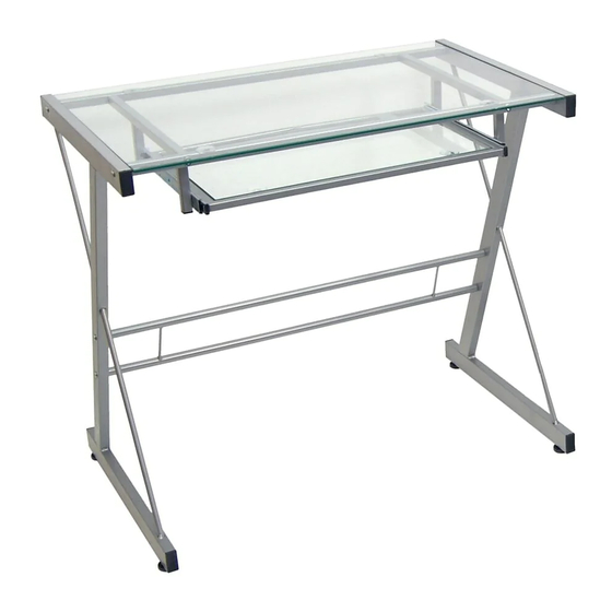
Walker Edison D31S29 Assembly Diagram
Hide thumbs
Also See for D31S29:
- Assembly instructions manual (16 pages) ,
- Assembly instructions manual (9 pages)
Advertisement
Quick Links
Assembly Diagram
Model No.
A
B
C
D
E
F
G
*Note: These parts come preassembled for shipping purposes and must be disassembled for assembly
Component List
1
wrench
8
small screws
12
medium bolts
4
desk feet
rubber suction
8
cups
2
desk leg
1
desk glass
H*
I*
J
K
L
M
N
1
keyboard tray
2
bracket
keyboard tray
2
arm
keyboard tray
L = 1, R = 1
support frame
keyboard tray
1
glass
keyboard tray
1
frame
1
cross bar
cross bar for
2
frame keyboard
side
Advertisement

Related Manuals for Walker Edison D31S29


Summary of Contents for Walker Edison D31S29
- Page 1 Assembly Diagram Model No. Component List keyboard tray wrench bracket keyboard tray small screws keyboard tray L = 1, R = 1 medium bolts support frame keyboard tray desk feet glass keyboard tray rubber suction frame cups desk leg cross bar cross bar for desk glass frame keyboard...
-
Page 2: Assembly Diagram
Assembly Diagram Model No. D51Z29 Model No. D51L29 Model No. Step 1 Screw desk feet (G) into the bottom of desk legs (N). Step 2 Take legs (F) and screw in the medium bolts (C) into and through the legs (F) and into the upper cross bars (N). - Page 3 Assembly Diagram Model No. Step 4 Screw in keyboard support tray frame (J) between left upper cross bars (N) using medium bolts (C). Step 5 Disassemble the keyboard tray brackets (H) and the keyboard tray arm (I) by pressing down the small lever and pulling up. Step 6 Attach keyboard tray arm (I) to keyboard support tray frame (J) using small screws (B).
- Page 4 Assembly Diagram Model No. Step 8 To construct the keyboard tray you need to take the keyboard tray brackets (H) and secure them to the keyboard frame (L) using small screws (B) as shown in the illustration. *Note: Ensure the open end of keyboard tray arm (I) faces front side of desk. Push down on small lever to allow keyboard bracket to slide along...
- Page 5 Assembly Diagram Model No. Final Assembly...