Advertisement
Quick Links
Manual de Instalación
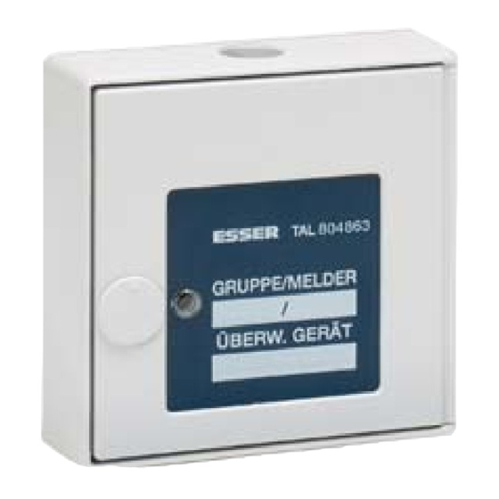
Módulo de Alarma Técnica (TAL)
Installation Instruction
Technical Alarm Module (TAM)
(Ref. / Part. No. 804863, 804864, 805863, 805864)
798831
Cambios técnicos reservados!
E
GB
06.2007
Technical changes reserved!
Novar GmbH a Honeywell Company
Dieselstraße 2, D-41469 Neuss
Internet:
www.esser-systems.de
E-Mail:
info@esser-systems.de
E
Durante la revisión de los módulos TAL, deben tenerse en
cuenta la activación de alarmas y conexión a sistemas
centralizados de alarma remotos (como Master Box).
Información adicional y actualizada
Las especificaciones se refieren al la fecha de creación del
documento y pueden ser modificadas o variadas sobre la
normativa aplicada o la información facilitada.
Para
obtener
la
información
mantenimiento o configuración de los sistemas, contacte
con su proveedor para que se la facilite o en
www.esser-systems.de.
GB
The alarm activation and triggering of notifying systems e.g.
manned centre link (Master box) must be observed during
any Service of the TAM.
Additional and updated Informations
The product specification relate to the date of issue and
may differ due to modifications and/or amended Standards
and Regulations from the given informations.
For
updated
informations
maintenance
of
Fire
alarm
www.esser-systems.de.
Importante!
Estas instrucciones deben ser tenidas en cuenta cuidadosamente
antes de proceder a la puesta en marcha del Módulo de Alarma
Técnica. Devoluciones bajo garantía serán invalidadas en caso de
avería causada por no seguir estas instrucciones. No se aceptará
responsabilidad por ningún tipo de pérdidas derivadas.
Instrucciones de Seguridad
•
No conecte el módulo TAL a alimentación de 220 Vca.
•
El módulo TAL solo puede usarse dentro de los límites de
temperatura de trabajo.
•
Solo técnicos cualificados que estén familiarizados con los
riesgos específicos y las normativas correspondientes deben
llevar a cabo las operaciones de reparación y mantenimiento
del TAL.
•
El módulo TAL solo puede conectarse a centrales 8000 /
IQ8Control.
•
El módulo TAL solo puede conectarse en interiores.
•
No realice modificaciones sobre el módulo.
Conexionado Fig. 1
El módulo de Alarma Técnica (TAL) se conecta al lazo analógico
de sistemas 8000 / IQ8Control para reconocimiento, transmisión e
indicación individual de alarmas técnicas.
Tipos de TAL
Entrada
Optoacoplada
Optoacoplada
Optoacoplada
Optoacoplada
TAL con aislador (Ref. 80x863)
Los aisladores de lazo permiten el funcionamiento en caso de
cortocircuito en el cableado de lazo.
Los aisladores más próximos al cortocircuito abren (aíslan) el
tramo de lazo, permitiendo la comunicación en el resto del lazo.
Un único cortocircuito entre aisladores no afectará al
funcionamiento del resto del lazo.
TAL con salida de Relé (Ref. 80x864) Fig. 2
La conexión del relé NC/C (normalmente cerrado) y C/NO
(normalmente abierto), puede usarse para realizar maniobras
externas. El contacto puede activarse cuando el TAL esté
activado. El relé se configura por activación de zonas como
cualquier salida.
Indicador Remoto. Fig. 3
Es posible conectar un LED indicador remoto de alarma. El
cableado para el indicador remoto no debe exceder el 100m!. Es
posible conectar los siguientes indicadores remotos. Ref: 781804,
781814 y 801824.
Entrada optoacoplada Fig. 4
Es posible conectar un contacto externo al módulo de Alarma
Técnica (TAL) mediante activación por tensión. Esta entrada no
es supervisada. En caso de no usar la entrada normal de alarma,
ésta deberá cerrarse con resistencia de 10KOhm.
Conexión de Pulsadores de Alarma Fig. 5 / 6
El módulo TAL permite conectar pulsadores de alarma
convencionales con resistencia de alarma de 1K a la entrada D-
Line. En caso de alarma de cualquier pulsador conectado al TAL,
se indicará como alarma del Tal según su configuración de
dirección y zona La longitud máxima del cableado de la línea no
excederá de 500m!. El último equipo deberá disponer de
resistencia final de línea de 10 KOhm.
Si no se usa la entrada de alarma Técnica, deberá colocarse una
resistencia final de línea de 10 KOhms ( véase Fig. 5) entre los
terminales de D-Line (Configuración de fábrica desde equipos con
índice D).
Rearme
La activación de alarma del Tal es enclavada.
Para rearmar el TAL, rearme el panel o conecte la zona
correspondiente.
Datos Técnicos
Alimentación:
Relés
-Límite Contacto:
actualizada
para
-Tipo de contacto:
Entrada Optoacoplada:
Consumo Reposo (19 V)
Consumo Alarma:
Indicador de alarma:
Terminales:
Temperatura ambiental:
Temp. almacenamiento:
Grado Protección:
Caja:
Color:
Peso:
Dimensiones (a x h x f)
to
commissioning
and
detectors
refer
to
E
Compruebe la dirección del cableado:
(entrada) ⇒ -UL
X1, terminal -UL
(salida).
(IN)
(OUT)
Use cable tipo IY (St) Y n x 2 x 0,8 mm con la
especificación adecuada para sistemas de detección de
incendio!. La pantalla evitará posibles interferencias.
Salida/Tipo
Caja
Aislador
Plástico ABS
Aislador
Makrolon
Relé
Plástico ABS
Relé
Makrolon
Revise el límite máximo del contacto 30V DC / 1A!
8 V cc bis 42 V cc
30 V cc / 1 A
Contacto seco
2,4 V cc a 24 V cc /
0,4 a 15 mA
45 μA aprox.
typ. 9 mA, pulsante
LED, Rojo
1,5 mm² max.
-20 °C a +70 °C
-30 °C a +75 °C
IP 42
Plástico ABS
Grís blanco
200 g apróx.
124 x 124 x 38
122 x 120 x 55
(mm)
Warning!
These installation instructions must be studied carefully before
commissioning the Technical Alarm Module. Claims under
warranty will be invalidated in the event of damage caused by non-
compliance with the installation instructions. No liability is accepted
for any resulting consequential loss.
Safety instructions
•
It is not allowed to connect the TAM to the mains supply.
•
The TAM can only be used in the appropriate temperature
range.
•
Maintenance and Service of the TAM must be qualified
personnel which is familiar with the regulations and the related
dangers.
•
The TAM can only be connected to Fire Alarm System 8000 /
IQ8Control.
•
It is only allowed to install the TAM indoors.
•
It is not allowed to modify the TAM.
Wiring Fig. 1
The Technical Alarm Module (TAM) is connected to the analog
loop of the series 8000 / IQ8Control fire alarm system for
recognition, transmission and individual display of technical
alarms.
Observe the direction of the wiring:
X1, terminal -UL
Use cable IY (St) Y n x 2 x 0,8 mm with special
specification or fire detection cable!
The shielding is used to prevent EMI.
Versions of TAM
Ref.
Input
Type/Output
804863
Optocoupler
805863
Optocoupler
804864
Optocoupler
805864
Optocoupler
TAM with isolator (Part No. 80x863)
Loop isolators provide the operation in case of a short circuit on
the loop.
The isolators next to the short circuit opens and disables the
section between the two isolators on the loop.
A single wire break does not take affect to the proper operation
of the loop.
TAM with relay output (Part No. 80x864) Fig. 2
The connectors of the 2nd micro switch NC/C (normally closed)
and NO/C (normally open) may be used to control external
devices. The contact will be closed when the TAL has been
released. The relay output may be triggered by a programmed
control zone in the customer data of the FACP.
Observe max. contact rating 30V DC / 1A!
Remote indicator Fig. 3
A remote LED indicator is used for an optical indication of alarm
condition. The maximum length of wire for the remote LED
indicator can not be more than 100 m! The following Remote LED
Indicators may be connected: Part No. 781804, 781814 and
801824.
Optocoupler input Fig. 4
It is possible to connect an external alarm contact (e.g. switch) to
the intelligent Technical Alarm Module. The input is not monitored.
The unused input of the external D-Line must be terminated with
an End-of-line 10KOhm resistor.
Connection of an external detector zone Fig. 5 / 6
One TAM provides the connection of an external detector zone
(D-Line) with up to 10 conventional Manual call points and an
internal alarm 1KOhm resistor per MCP (not according to VdS). If
activated the address and the programmed additional text of the
TAM, where the external zone is connected to, will be displayed.
The maximum length of the cable for the external D-Line must not
exceed 500 meters! The last detector of the external zone must be
terminated with a 10KOhm End-of-line resistor.
If no external D-Line is connected the 10KOhm terminating
resistor (factory default from Hardware index D) must be
connected directly to the terminals (refer to Fig. 5).
Reset
The TAM activation is latching.
To reset the TAM reset FACP or corresponding zone.
Technical Data
Operating voltage:
Relay
-Contact rating:
-Change over contact:
Optocoupler:
Quiescent current @ 19 V DC:
Alarm current:
Alarm indicator:
Terminals:
Ambient temperature:
Storage temperature:
IP 54
Makrolon
Protection rating:
Blanco
Housing:
300 g aprox.
Colour:
Weight:
(mm)
Dimensions (w x h x d):
GB
(input) ⇒ -UL
(output).
(IN)
(OUT)
Housing
Part No.
Isolator
ABS plastic
804863
Isolator
Makrolon
805863
Relay
ABS plastic
804864
Relay
Makrolon
805864
8 V DC to 42 V DC
30 V DC / 1 A
floating contact
2,4 V DC to 24 V DC /
0,4 to 15 mA
ca. 45 μA
typ. 9 mA, pulsed
LED, red
max. 1,5 mm²
-20 °C to +70 °C
-30 °C to +75 °C
IP 42
IP 54
ABS plastic
Makrolon
grey white
white
approx. 200 g
approx. 300 g
124 x 124 x 38
122 x 120 x 55
(mm)
(mm)
Advertisement

Related Manuals for Honeywell ESSER TAM


Summary of Contents for Honeywell ESSER TAM
- Page 1 Tal según su configuración de internal alarm 1KOhm resistor per MCP (not according to VdS). If Novar GmbH a Honeywell Company dirección y zona La longitud máxima del cableado de la línea no activated the address and the programmed additional text of the excederá...
- Page 2 Conexiones Wiring SCHIRM -UL -UL SCHIRM -UL -UL SCHIRM -UL -UL Fig. 1 : Ejemplo, conexionado lazo analógico sistema 8000 / IQ8Control Fig. 1 : Example, analog loop wiring, fire alarm system 8000 / IQ8Control Art.-Nr./Part No. 781804, 781814, 801824 NC C Input OPTO...
Need help?
Do you have a question about the ESSER TAM and is the answer not in the manual?
Questions and answers