
Related Manuals for KERN YPS-03


Summary of Contents for KERN YPS-03
- Page 1 KERN & Sohn GmbH Ziegelei 1 Phone: +49-[0]7433- 9933-0 D-72336 Balingen Fax: +49-[0]7433-9933-149 E-Mail: info@kern-sohn.com Internet: www.kern-sohn.com Installation Instructions Balance table KERN TYPS-03A-B Version 1.0 2020-08 TYPS-03A-B-IA-e-2010...
-
Page 2: Table Of Contents
KERN TYPS-03A-B Version 1.0 2020-08 Installation Instructions Balance table Contents Introduction ....................... 3 Technical data ....................3 Assembly of the weighing table ............... 4 Inner frame assembly ....................4 Outer frame assembly ....................8 Final assembly ......................10 Attendance ....................... 10... -
Page 3: Introduction
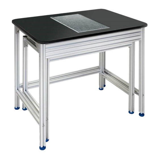
1 Introduction The KERN balance table was designed for laboratories and metrology rooms in order to create suitable working conditions for devices that react sensitively to vibrations and shocks. The table comprises two different components: • An integrated work space with shock-absorbing rubber blocks attached to a stone slab •... -
Page 4: Assembly Of The Weighing Table
(short) and the accessory bag from the lower packing layer. 3. Screw these parts together with the 4x M8x40 screws using the hexagon wrench key from the bag in a way the resulting frame is plane and flat. (See fig. 2) Fig. 2 YPS-03-IA-e-1910... - Page 5 1 x Supporting rail (lower) 6x M8x40 socket screws Figure 3 Inner frame assembly Take care that the screws are fitted in such a way that they are sunk in the recesses. (Do not allow screws to protrude - risk of injuries!) YPS-03-IA-e-1910...
- Page 6 4 rubbers Figure 4 Assembled inner frame YPS-03-IA-e-1910...
- Page 7 Figure 5 Correct position of the granite Figure 6 Assembled inner frame with granite YPS-03-IA-e-1910...
-
Page 8: Outer Frame Assembly
Figure 9 1x outer side rail 1x working surface 1x outer side rail (righthand) (lefthand) crossbatten outer frame (below) 1 x crossbatten outer frame (front top) Lower packing Middle packing Top packing Figure 7 Outer frame packing YPS-03-IA-e-1910... - Page 9 1 x Outer side rail (right) (left) 1x Table top assembly 10x M8 x 40 socket screws 1 x Outer table 1x Outer table supporting supporting rail (upper rail (lower) front) Figure 8 Outer frame assembly drawing Figure 9 Assembled outer frame YPS-03-IA-e-1910...
-
Page 10: Final Assembly
• Place the weighing table in a dry and clean environment. Do not install out of doors. Do not use in the vicinity of fire or in environments with high temperatures. Avoid exposure to direct sunlight. YPS-03-IA-e-1910...
Need help?
Do you have a question about the YPS-03 and is the answer not in the manual?
Questions and answers