Table of Contents
Advertisement
Advertisement
Table of Contents

Related Manuals for KERN KERN 440...N


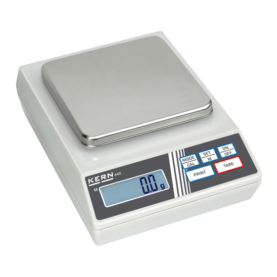
Summary of Contents for KERN KERN 440...N
- Page 1 KERN & Sohn GmbH Ziegelei 1 Tel: +49-[0]7433-9933-0 D-72336 Balingen Fax: +49-[0]7433-9933-149 E-Mail: info@kern-sohn.com Internet: www.kern-sohn.com Service Manual Page 2 Electronic Precision Balances KERN 440…N KERN 440…A Version 4.0 4/2008 440…N-SH-e-0840...
-
Page 2: Table Of Contents
KERN 440…N / 440…A Version 4.0 4/2008 Service Manual Electronic Precision Balances Table of Contents Features........................3 Calibration Procedure (CAL) ..................3 Internal Calibration Procedure (Linearity Adjustment) ........... 4 3.1 Readout of the Internal Counts.....................4 Display Segment Test ....................5 Functional Block Diagram / Description.............. -
Page 3: Features
1 Features • Full Tare • Memory function with indicator • Stable indicator • Negative value indication • Two types of Digital Auto Calibration • Solder pads to prevent end-user internal calibration • RS232 interface, printing function • Custom scale by going through SET manual Multiple serial interface modes Different communication baud rates selectable Auto off enable / disable... -
Page 4: Internal Calibration Procedure (Linearity Adjustment)
3 Internal Calibration Procedure (Linearity Adjustment) 1. Remove the top housing of the scale. 2. Connect J3 on the main board by soldering the pads together. 3. Place scale on a hard level surface. With weighing pan installed, turn scale on. Display shall show the internal counts. -
Page 5: Display Segment Test
4 Display Segment Test Whenever the scale is power on, all segments of the LCD will be turn on for approx. 5 seconds. Check for any missing segment. 5 Functional Block Diagram / Description 5.1 Functional Block Diagram External Computer / Printer Keyboard RS232 Serial... -
Page 6: Function Description
5.2 Function Description 1. Load cell This is the heart of the whole system. The load cell itself is arranged as a bridge. The resistance change of the bridge elements is proportional to the load applied on the load cell. Therefore, the output of the load cell is an analog signal, which is proportional to the load applied on the scale. -
Page 7: Trouble Shooting
6 Trouble Shooting Power on ↓ Full Segments? If no display, check battery /adaptor; connection between keyboard—main board, battery/adaptor—main board. If missing segments, check fixing of LCD frame, zebra connector under LCD. ↓ Display Zero? If display [LO], check battery>7.5V, adaptor>9V. If display [ E] , check internal count. -
Page 8: To Replace Pcb
7 To Replace PCB 1. Disassemble top housing of scale. 2. Disconnect PL1, PL2, PL3, JP1 and BZ1 from the PCB. Disassemble the ground wire screw. Replace a new PCB. Connect PL1, PL2, PL3, JP1 and BZ1 again. Assemble the ground wire with screw. 3. -
Page 9: To Replace Load Cell Assembly
8 To Replace Load Cell Assembly 1. Disassemble top housing of scale. 2. Disconnect PL2 from main PCB. Remove the four screws fixing the bottom plate of the load cell assembly. Replace the load cell with a new one. Connect PL2 and fix the four screws. 3. -
Page 10: Schematics
9 Schematics 440…N-SH-e-0840... - Page 11 440…N-SH-e-0840...
-
Page 12: Components Layout
10 Components Layout 440…N-SH-e-0840...
Need help?
Do you have a question about the KERN 440...N and is the answer not in the manual?
Questions and answers