Table of Contents
Advertisement
Quick Links
Advertisement
Table of Contents

Related Manuals for Galletti LEP Series


Summary of Contents for Galletti LEP Series
- Page 1 Multifunction heat pumps 40 – 420 kW...
- Page 2 Page 2 of 48 RG66007653– Rev.02 ...
-
Page 3: Table Of Contents
Contents CONTENTS ..............................3 1 GENERAL DESCRIPTION ........................5 1.1 T PRODUCT ..........................5 1.1.1 F IELD OF APPLICATION ........................... 6 1.1.2 I NNOVATION OF PRODUCT ........................9 1.2 S TRUCTURE ............................. 10 1.3 C OOLING CIRCUIT ..........................10 1.3.1 C OMPRESSORS ............................ - Page 4 4 OPERATING LIMITS: ........................44 4.1 U SE OF GLYCOL SOLUTIONS ....................... 44 4.2 W ORKING LIMITS ..........................44 4.3 W ATER FLOW TO EVAPORATOR ......................45 5 CALIBRATION OF CONTROL DEVICES ................... 46 Page 4 of 48 RG66007653– Rev.02 ...
-
Page 5: 1 General Description
“P” indicates a heat pump with total recovery for 4‐pipe systems, the letter “H” indicates multifunction heat pumps for 2‐pipe systems. The LEP units can be identified by the following symbol: LEP 072 HS 1 ‐ 1 ‐ Identification symbol of Galletti Model (e.g.: “LEP” units) ‐ 2 ‐ Unit sizes expressed in rated chilling output x10 [kW] (e.g.: 70 kW) ‐ 3 ‐ Efficiency Pack: layout of cooling circuit and compressors (e.g.: Efficiency Pack 2) ‐ 4 ‐ Unit version (e.g.: “H”, Multifunction) ‐ 5 ‐ Unit execution (e.g.: “S”, no optional soundproofing present) Page 5 of 48 RG66007653– Rev.02 ... -
Page 6: Field Of Application
1.1.1 Field of application LEP units are intended for cooling‐heating water and glycol solutions up to a maximum of 30% the weight, in civil, industrial and technological air conditioning environments. The use of LEP units is recommended within the functioning limits carried in this document, or else the warranty attached to the sales contract would cease. - Page 7 The following points schematise the operating functions of the LEP H multifunction unit: ‐ Chilling The LEP H multifunction unit in “Chiller” mode chills the water to cool the environment on the utility side, dissipating condensation heat by means of the water which is cooled by the dissipation heat exchanger. ‐ Heating The LEP H unit in “Heat Pump” mode heats the water in the condenser to heat the utility side, dissipating the evaporation cooling capacity by means of the water which is heated in the dissipation heat exchanger. In other words, a certain amount of heat is withdrawn from a thermal source which is then yielded to the utility after it has reached a sufficient thermal level which is suitable for its needs. ...
- Page 8 ‐ Production of high temperature hot water for domestic use The LEP H multifunction unit in “Production of high temperature Hot Water for domestic use” (DHW) mode heats the water in the condenser specific for DHW, dissipating the evaporation cooling capacity by means of the water which is heated in the dissipation heat exchanger. ‐ Cooling simultaneous to production of high temperature hot water for domestic use The LEP H multifunction unit, in “Chiller + DHW” mode, produces chilled water with the simultaneous production of high temperature hot water for domestic use, thanks to a total heat recovery. LEP units make it possible to install indifferently a simple 2 or 4 pipe air conditioning system. The two or four pipe designation ...
-
Page 9: Innovation Of Product
‐ 2‐pipe air conditioning system layout: ‐ 4‐pipe air conditioning system layout: The 2‐pipe systems are less flexible than 4‐pipe systems because the entire building is either heated or cooled, though the installation greatly saves energy. If the design requires a 4‐pipe system, the LEP range provides, on demand, the P units which are compatible with this configuration. 1.1.2 Innovation of product LEP units provide excellent thermodynamic performance and the maximum flexibility of use thanks to a constant research: they can drive either 2 or 4 pipe systems, produce DHW together with cold water, and cover a wide range of ... -
Page 10: Structure
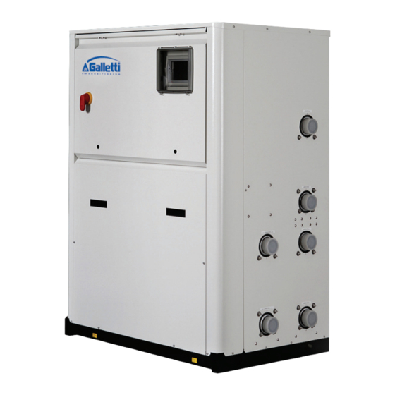
Structure All of the LEP series units are constructed with a support base and panelling made of galvanised sheet metal painted with black polyester epoxy powders oven‐polymerised at 180°C. The unit has an exclusive design enhancing the overall assembly with a smart outward appearance. Moreover the closed unit makes the components inaccessible: this aspect together with the wide use of soundproof material inside the compartment and around the compressors (optional for low‐noise version) reduces the emitted sound output to exceptionally low levels (Lp < 67 dB‐A @1 metre for larger sizes). The hydraulic/chiller connections are envisioned on the right side, when looking at the electrical control board, to reduce the technical space required for installation. All the panels are removable (except for the one on the right, upon ... -
Page 11: Heat Exchangers
‐ N.B.: due to thermal insulation, the data plate in compliance with PED CE 97/23 is not legible, but the serial number of the heat exchanger and the declaration of conformity are detected during production and are an integral part of the Galletti archive. 1.3.3 Utility and dissipation side cycle inversion valves (optional) When LEP H reversible chillers switch from chiller to the heat pump and vice versa, they perform two cycle inversions: one refrigerant side and one water side. The inversion valve of the water‐side cycle switches from position A to position B and vice versa, by means of an electrical driver without changing the travel direction for the outside utilities. This allows to invert the flow direction in the heat exchangers, keeping them against the flow respect to the refrigerant fluid ... -
Page 12: Electronically Controlled Expansion Valve
Refrigerant‐side cycle inversion valve Heat‐transfer fluid‐side cycle inversion valve 1.3.4 Electronically controlled expansion valve The electronic control valve with external equalisation and built‐in MOP function is managed by the software and therefore makes the cooling circuit operation very efficient, decreasing the power absorbed by the system when a sudden ... -
Page 13: Other Cooling Components
1.3.5 Other cooling components ‐ Molecular sieve filter dryer ‐ Sight glass with humidity indicator ‐ One‐way valves (only reversible heat pump) ‐ Liquid receiver marked in compliance with EEC Directive 97/23 PED (only reversible heat pumps or units with remote condenser) ‐ High and low pressure switches ‐ Solenoid valves for management of different air conditioning and DHW production modes (only for multifunction versions) ‐ Schrader valves for control and/or maintenance Page 13 of 48 RG66007653– Rev.02 ... -
Page 14: General Thermodynamic Circuit Layouts
Compressor 1.3.6 General thermodynamic circuit layouts Liquid receiver Standard layout of thermodynamic circuit of LEP units in cooling mode Liquid separator Plate heat exchanger Control processor 8 EVAPORATOR Expansion valve (UTILITY) Filter Solenoid valve One‐way valve Liquid indicator 5 CONDENSER (DISSIPATION) 3 6 10 Standard layout of thermodynamic circuit of LEP units in heating mode CONDENSER (UTILITY) EVAPORATOR (DISSIPATION) Page 14 of 48 RG66007653– Rev.02 ... - Page 15 Standard layout of thermodynamic circuit of LEP units for DHW production CONDENSER (DHW) EVAPORATOR (DISSIPATION) Standard layout of thermodynamic circuit of LEP units in cooling mode with simultaneous DHW production CONDENSER EVAPORATOR (DHW) (UTILITY) Page 15 of 48 RG66007653– Rev.02 ...
-
Page 16: Electrical Control Board
High/ low pressure ‐ Antifreeze ‐ Flow switch ‐ Pump alarm ‐ Alarm signals ‐ Display of operation parameters ‐ Antifreeze protection of evaporator ‐ Control of maximum number of compressor starts ‐ Serial output control (optional) RS232, RS485 ‐ Incorrect sequence phases (not viewed on display, but keeps compressor from starting) As for remote communication, the controls are set‐up for connection with advanced BMS systems and the HSD (Galletti Software Department) structure is capable of assisting customers in integration operations. The interconnectivity possibilities of the system are synthesised as follows: ‐ Serial ports available ‐ RS232 ‐ RS485 ‐ Ethernet (“Hiweb” board) ‐ GSM Modem: with prepaid card and relative antenna on‐board machine for autonomous two‐way control of alarms and/or set‐point variations ‐ Protocols ‐ Carel [Built In] ‐... -
Page 17: Configurability , Accessories And Options
Configurability, accessories and options Variants of LEP product: ‐ Soundproofing: ‐ Standard unit not equipped with sound insulation ‐ Low‐noise unit through sound‐absorbing housing for each compressor and insulation of frame panels with sound‐absorbing textured material ‐ Rubber‐based or spring anti‐vibration devices ‐ Thermal distribution system (software set‐up): ‐ 2 pipes: single distribution circuit ‐ 4 pipes (on demand): namely two separate circuits, hot and cold ‐ Downgrade to mechanical expansion valve, on demand (the electronic controlled expansion valve is standard) Options of LEP product: ‐ Thermodynamic circuit ‐ Condensation control via 0‐10 V signal of external modulating device (2‐way valve, 3‐way valve, variable speed circulation pump) ‐ Outdoor temperature probe for set‐point compensation ‐ Analogue pressure gauges ‐ Electrical control board: ‐ Power supply in 400/3+N/50 Hz with motor circuit breakers ‐ Shunt capacitors ... -
Page 18: 2 Technical Data
Technical data Table I – Technical data of LEP H models from LEP 1 040 to LEP 1 160 in standard operating conditions for vertical probe geothermic application Synthesis of LEP series 041/2 051/2 061/2 071/2 081/2 091/2 111/2 131/2 141/2 144 161/2 164 technical data Cooling @ 30/35 ; W12/7 47,6 56,3 64,9 73,4 84,6 94,0 114 130 149 149 167 167 Cooling Capacity [kW] 10,5 13,5 14,7 17,0 18,4 ... - Page 19 Table II – Technical data of LEP H models from LEP 1 180 to LEP 4 420 in standard operating conditions for vertical probe geothermic application Synthesis of LEP series 181/2 184 204 214 243 244 283 284 314 344 374 424 technical data Cooling @ 30/35 ; W12/7 199 193 209 228 256 266 294 298 328 359 390 445 Cooling Capacity [kW] 42,9 41,2 45,1 48,4 54,5 ...
-
Page 20: Performance Of Lep Pand Hheat Pump Units
Performance of LEP P and H heat pump units All the data in the paragraph refers to ΔT = 5°C on evaporation and condensation side. Pf = chiller power [kW]; Pa = absorbed power [kW]. In order to calculate the thermodynamic EER and COP factors, take the Pf / Pa ratio. Performance has been obtained with different glycol percentages in the solution even though, from a thermodynamic point of view, with up to 30% of glycol in solution, the performance drop recorded is minor: nonetheless refer to the paragraph 4.1 “Use of glycol solutions” for further information. Table III: performance of LEP H P units in cold water production mode using water without glycol. LEP P – LEP H Tcond 10/30 15/30 20/30 [°C] Size Tev [°C] Pf Pa Pf Pa Pf Pa 20/15 65,9 8,6 66,5 9,5 65,2 8,9 LEP 041/2 15/10 56,5 56,2 56,1 8,9 10/5 49,0 ... - Page 21 10/5 272,5 44,8 270,8 45,5 266,2 46,8 20/15 408,6 53,9 406,5 54,7 403,6 55,6 LEP 283 15/10 352,5 53,4 350,4 54,2 346,0 55,7 10/5 301,8 52,7 53,6 296,2 54,9 20/15 413,7 54,3 411,4 54,9 408,9 55,9 LEP 284 15/10 357,5 53,2 354,8 54,2 349,9 55,6 ...
- Page 22 0/‐5 127,6 30,2 123,05 38,1 118,5 46 15/10 195,6 185,5 38,7 174,1 47,1 10/5 171,4 31,5 162,9 39,1 154,4 46,7 LEP 144 5/0 149,2 142,85 38,65 136,5 46,3 0/‐5 128,7 30,5 124,3 38,1 119,9 45,7 15/10 218,6 35,3 206,3 42,8 192,5 52,1 ...
-
Page 23: Characteristic Curves Of The Hydraulic Pumps Associated To The Units
Characteristic curves of the hydraulic pumps associated to the units The graphics displayed in this paragraph show the useful head expressed (the net value of the internal losses of the units) of the HP pumps and LP pumps in the optional hydronic module. Refer to the paragraph 4.1 “Use of glycol solutions” to assess the effect of glycol on the useful head offered by the pumps; the corrective coefficients to be applied to the curves, calculated in pure water, are carried here to facilitate consultation. At the nominal flow rates listed in Tables I and II in this chapter, the low‐pressure LP pumps provide 60 kPa of useful head on the utility and DHW side and 70 kPa on the dissipation side. The high‐pressure HP pumps provide 140 kPa useful head for the dissipation side and utility side. Useful head for pumps on utility side LEP 041, 042 Useful head for pumps on utility side LEP 051, 052 Useful head for pumps on utility side LEP 061, 062, 071, 072 Useful head for pumps on utility side LEP 081, 082 Useful head for pumps on utility side LEP 091, 092 Useful head for pumps on utility side LEP 111, 112, 131, 132 Page 23 of 48 RG66007653– Rev.02 ... - Page 24 Useful head for pumps on utility side LEP 141, 142, 144 Useful head for pumps on utility side LEP 161, 162, 164 Useful head for pumps on utility side LEP 181, 182, 184 Useful head for pumps on utility side LEP 204 Useful head for pumps on utility side LEP 214 Useful head for pumps on utility side LEP 243, 244 Useful head for pumps on utility side LEP 283, 284 Useful head for pumps on utility side LEP 314 Page 24 of 48 RG66007653– Rev.02 ...
- Page 25 Useful head for pumps on utility side LEP 344 Useful head for pumps on utility side LEP 374 Useful head for pumps on utility side LEP 424 Useful head for pumps on dissipation side LEP 041, 042 Useful head for pumps on dissipation side LEP 051, 052 Useful head for pumps on dissipation side LEP 061, 062 Useful head for pumps on dissipation side LEP 071, 072 Page 25 of 48 RG66007653– Rev.02 ...
- Page 26 Useful head for pumps on dissipation side LEP 081, 082 Useful head for pumps on dissipation side LEP 091, 092 Useful head for pumps on dissipation side LEP 111, 112 Useful head for pumps on dissipation side LEP 131, 132 Useful head for pumps on dissipation side LEP 141, 142 Useful head for pumps on dissipation side LEP 144 Useful head for pumps on dissipation side LEP 161, 162, 164 Useful head for pumps on dissipation side LEP 181, 182, 184 Page 26 of 48 RG66007653– Rev.02 ...
- Page 27 Useful head for pumps on dissipation side LEP 204 Useful head for pumps on dissipation side LEP 214 Useful head for pumps on dissipation side LEP 243 Useful head for pumps on dissipation side LEP 244, 283, 284 Useful head for pumps on dissipation side LEP 314 Useful head for pumps on dissipation side LEP 344 Useful head for pumps on dissipation side LEP 374 Useful head for pumps on dissipation side LEP 424 Page 27 of 48 RG66007653– Rev.02 ...
- Page 28 Useful head for pumps on DHW side LEP 041, 042 Useful head for pumps on DHW side LEP 051, 052 Useful head for pumps on DHW side LEP 061, 062, 071, 072 Useful head for pumps on DHW side LEP 081, 082 Useful head for pumps on DHW side LEP 091, 092 Useful head for pumps on DHW side LEP 111, 112 Page 28 of 48 RG66007653– Rev.02 ...
- Page 29 Useful head for pumps on DHW side LEP 131, 132 Useful head for pumps on DHW side LEP 141, 142 Useful head for pumps on DHW side LEP 144 Useful head for pumps on DHW side LEP 161, 162, 164 Useful head for pumps on DHW side LEP 181, 182, 184 Useful head for pumps on DHW side LEP 204 Useful head for pumps on DHW side LEP 214 Useful head for pumps on DHW side LEP 243 Page 29 of 48 RG66007653– Rev.02 ...
-
Page 30: Noise Emission
Useful head for pumps on DHW side LEP 244, 283, 284, 314 Useful head for pumps on DHW side LEP 344 Useful head for pumps on DHW side LEP 374 Useful head for pumps on DHW side LEP 424 Noise emission WE units have been built in a fully faired framework making the assembly extremely silent. They can therefore be installed in open environments without needing to be closed off. All sizes of the WE series are available in the standard "S" set‐up or the "L" (Low‐noise) soundproof set‐up, covering the compressor and outer panelling with soundproof material. Table V: noise emissions of LEP units: Lw: Sound power Lp: Sound pressure Sizes: 040 050 060 070 080 090 110 130 140 160 180 200 210 240 280 ... -
Page 31: Overall Dimensions And Weight
Overall dimensions and weight The LEP product range consists in different frames. In the following paragraph, the overall drawings of the LEP models and their optional modules are attached. They can be referred to directly when consulting the identification codes carried in the tables in this paragraph. The tables below list the weights, reference drawings and overall dimensions of all the LEP models as well as their optional hydraulic modules. The overall drawings of reference are displayed in the following paragraph. Table VI: overall dimensions of frames of main units (F_) and optional hydraulic modules (M_) used in LEP range Frame of main unit Height (H) Width (L) Depth (P) 1594 F1 1183 781 F2 1594 1653 F3 1854 2383 1855 F4 3130 881 Table VII: weight of the LEP units. Model: 040 050 060 070 080 090 110 130 140 ... -
Page 32: Overall Drawings
Overall Drawings Frame 1 1 User side ‐ inlet (Victaulic 2½”) 2 User side ‐ outlet (Victaulic 2½”) 3 DHW side ‐ inlet (Victaulic 2½”) 4 DHW side ‐ outlet (Victaulic 2½”) 5 Dissipation side ‐ inlet (Victaulic 2½”) 6 Dissipation side ‐ outlet (Victaulic 2½”) 7 User interface 8 Power supply input Page 32 of 48 RG66007653– Rev.02 ... - Page 33 Frame 2 1 User side ‐ inlet (Victaulic 2½”) 2 User side ‐ outlet (Victaulic 2½”) 3 DHW side ‐ inlet (Victaulic 2½”) 4 DHW side ‐ outlet (Victaulic 2½”) 5 Dissipation side ‐ inlet (Victaulic 2½”) 6 Dissipation side ‐ outlet (Victaulic 2½”) 7 User interface 8 Power supply input Model Version LEP 112 M‐P S‐L LEP 132 M‐P S‐L LEP 142 M‐P S‐L LEP 162 M‐P S‐L LEP 182 M‐P S‐L ...
- Page 34 Frame 3 1 User side ‐ inlet (Victaulic 2½”) 2 User side ‐ outlet (Victaulic 2½”) 3 DHW side ‐ inlet (Victaulic 2½”) 4 DHW side ‐ outlet (Victaulic 2½”) 5 Dissipation side ‐ inlet (Victaulic 2½”) 6 Dissipation side ‐ outlet (Victaulic 2½”) 7 User interface 8 Fastening points 9 Power supply input Model Version LEP 144 M‐P S‐L LEP 164 M‐P S‐L LEP 184 M‐P S‐L Page 34 of 48 RG66007653– Rev.02 ...
- Page 35 Frame 4 LEP204 LEP214 1 User side ‐ inlet (Victaulic 2½”) 2 User side ‐ outlet (Victaulic 2½”) 3 DHW side ‐ inlet (Victaulic 2½”) 4 DHW side ‐ outlet (Victaulic 2½”) 5 Dissipation side ‐ inlet (Victaulic 2½”) 6 Dissipation side ‐ outlet (Victaulic 2½”) 7 User interface 8 Fastening points 9 Power supply input Model Version LEP 204 M‐P S‐L LEP 214 M‐P S‐L Page 35 of 48 RG66007653– Rev.02 ...
- Page 36 Frame 4 LEP244 284 314 374 424 1 User side ‐ inlet (Victaulic 2½”) 2 User side ‐ outlet (Victaulic 2½”) 3 DHW side ‐ inlet (Victaulic 2½”) 4 DHW side ‐ outlet (Victaulic 2½”) 5 Dissipation side ‐ inlet (Victaulic 2½”) 6 Dissipation side ‐ outlet (Victaulic 2½”) 7 User interface 8 Fastening points 9 Power supply input Model Version LEP 243 M‐P S‐L LEP 244 M‐P S‐L LEP 283 M‐P S‐L LEP 284 M‐P S‐L LEP 314 M‐P S‐L LEP 344 M‐P S‐L LEP 374 M‐P S‐L LEP 424 M‐P S‐L Page 36 of 48 RG66007653– Rev.02 ...
-
Page 37: 3 Installation
Installation Preliminary procedures Upon receiving the unit, check that it is perfectly intact: the chiller left the factory in perfect conditions; immediately report any signs of damage to the carrier and note them on the Delivery Slip before signing it. Galletti or its Agent must be promptly notified concerning the extent and type of damage. The Customer must submit a written report describing every significant sign of damage. 3.1.1 Lifting and conveyance While the unit is being unloaded and positioned, utmost care must be taken to avoid abrupt or violent manoeuvres. The unit must be handled carefully and gently. Avoid using machine components as anchorages when lifting or moving it. The unit should be lifted using Ø1½” GAS steel pipes at least 3mm thick, to be inserted in the holes provided on the base side members (see fig. below) and identified by means of stickers. The pipes, which should protrude by at least 300mm on every side, must be slung with ropes of equal length secured to the lifting hook (provide stops at the ends of the pipes to prevent the ropes from slipping off due to the weight). Use ropes or belts long enough to extend beyond the height of the unit and place spacer bars and boards on the top of the unit to avoid damaging the sides and top of the unit itself. Attention: In all lifting operations make sure that the unit is securely anchored in order to prevent accidental falls or overturning. 3.1.2 Unpacking ... -
Page 38: Installation Clearance Requirements
‐ accessibility for maintenance or repairs; ‐ solidity of the supporting surface. All the models of the LEP series have been designed and built for indoor or outdoor installations. Due to the special care given to soundproofing and the fact that components and hot parts in general are closed inside, they do not require special rooms. It is advisable to place a rigid anti‐vibration rubber strip between the base frame and the supporting surface. In the vicinity of open flames or in a room without sufficient air exchange, should refrigerant leak, it could catch fire and become harmful for persons deriving from toxic combustion products. -
Page 39: Hydraulic Connection To Evaporator
3.2.1 Hydraulic connection to evaporator The LEP series units have no internal water unit fitted, as it is fitted externally to the unit. It is extremely important that the water inlet corresponds with the connection marked with the writing “Water Inlet”. Otherwise the evaporator would be exposed to the risk of freezing since the antifreeze thermostat would not be able to ... -
Page 40: Filling Tank And / Or Pumps ( If Foreseen By The System )
A standard feature of LEP units is a device for controlling the water flow rate (blade-type flow switch included in supply). Any tampering with said device will immediately invalidate the warranty. It is recommended to install a metal net filter on the water inlet piping. Attention: During hydraulic connection operations, never work with open flames near or inside the unit. -
Page 41: Electric Connections Of The Circulation Pump
Electric connections of the circulation pump All the units of the LEP series are provided with a voltage‐free contact in the electrical control board with which a low‐ voltage consent for the pump to start is powered. Since it is an integral part of the supply, the pump must be started before the chiller and stopped after the latter (minimum recommended start delay: 60 seconds). If connected to the terminal in the electrical control board, this function is already performed by the microprocessor on the unit. -
Page 42: Commissioning Instructions For Lep Series Chillers
‐ Make sure that the water circuit is duly bled to completely eliminate the presence of air: fill the circuit gradually and open the air vent valves on the top part, which the installer should have set in place. 3.5.1 Commissioning instructions for LEP series chillers Hydraulic connections: ‐ Attention: the machine is loaded with HFC R410A refrigerant – Group II EN 378 (non‐hazardous substances) and in compliance with that prescribed by the EEC regulation 2037/00. ‐ Hydraulic connections must be carried out respecting the inlets and outlets as marked on the connections. Pay special attention not to invert the condenser and evaporator circuits. ‐ Provide cut‐off valves on the water side to be able to intercept the unit respect to the system and insert a net filter (which can be inspected) both on the evaporator side and on the condenser side. ‐ Load the hydraulic circuit making sure to bleed all the air inside of it. Electrical connections: ‐ Open the main switch, turn the locking screws of the electric panel ½‐turn and open it. ‐ Introduce the power cable 400/3/50+N through the hole provided on the left side of the unit and secure it with a cable gland. ‐ Connect the power supply and earthing wire to the terminals of the main switch. ‐ Disconnect the “QF” circuit breaker of the compressor to prevent it from starting up in the wrong direction in the event of an incorrect phase sequence. ‐ Only for mCH2 control ‐ Place the Local/remote selector button (SLR) in the centre at the top of the electrical control board at LOCAL and power it by turning the main switch (IG) to ON. ‐ Verify whether the phase sequence R‐S‐T is correct by checking the phase sequence relay situated in the middle of the electric control board is lit green: if this does not occur, disconnect the unit power supply from the external distribution panel and swap over two phases; then repeat the operation. IN NO CASE SHOULD YOU TAMPER WITH THE WIRING DOWNSTREAM FROM THE MAIN SWITCH since this may alter the correct sequence of other devices, e.g. pump(s). ‐ Rearm the “QF” compressor circuit breaker. ... -
Page 43: Checks During Operation
The degree of sub‐cooling is given by the difference between the temperatures thus determined. Attention: all the units of the LEP series are loaded with R410A refrigerant except for the versions with remote condenser which are loaded with nitrogen. Eventual top-ups must be done with the same type of refrigerant and are part of the routine maintenance operations performed by qualified personnel. -
Page 44: 4 Operating Limits
Operating limits: This paragraph carries a list of operating limits of the LEP chillers relating to water outlet temperature on the utility side and water inlet temperature at the dissipation heat exchanger. For applications with water T greater than the limits indicated, they must run with R134a refrigerant (on demand). For relevant details contact the zone Agent. Water temperature Minimum Maximum N.B. Evaporator inlet (cooling 10 20 Without using anti‐freeze phase) Condenser inlet (cooling Below 15°C , condensation 25 45 phase) pressure must be controlled Evaporator inlet (*) 9 45 Without using anti‐freeze (heating phase) Condenser inlet (*) 25 45 Without using anti‐freeze (heating phase) (*) in heat pump mode, the heat exchangers operate with inverted function. Use of glycol solutions Water can be produced at temperatures below 5°C as low as ‐10°C by using glycol solutions which lower the freezing point as shown in the following table: Minimum temperature of 5 °C ... -
Page 45: Water Flow To Evaporator
Water flow to evaporator The nominal flow rate is based on a temperature differential of 5° C between inlet and outlet water, in relation to the cooling capacity provided at the nominal water (12/7 °C) temperatures. The maximum allowed flow rate is associated with a temperature differential of 3 °C. Higher flow rates cause high drops in pressure. The minimum allowed flow rate is associated with a temperature differential of 8 °C. lower flow rates could cause excessively low evaporation temperatures, which may trigger the safety devices and cause the unit to stop, or else incorrect distribution and risk of thermal exchange with non‐turbulent or not‐fully‐turbulent motion conditions. Page 45 of 48 RG66007653– Rev.02 ... -
Page 46: 5 Calibration Of Control Devices
Calibration of control devices All of the control equipment is calibrated and test inspected at the factory before the unit is shipped. However, after the unit has worked for a reasonable amount of time, a control of the operation and safety devices may be carried out. The calibration values are carried on Tables I and II. All servicing of the control equipment is part of extraordinary maintenance and must be carried out EXCLUSIVELY BY QUALIFIED PERSONNEL: incorrect calibration values can seriously damage the unit and persons as well. Many of the functioning parameters and calibrations of the control systems which affect the integrity of the unit are set ... - Page 47 120 seconds. It is rearmed automatically only when pressure has risen above the value indicated by the set differential (see Table II). Calibration of service thermostat function The function of this device is to start and stop the compressors according to the water temperature reading at the chiller unit inlet [water returning from the circuit]. Refer to section of document concerning microprocessor control for further details. Calibration of antifreeze thermostat function The antifreeze probe is located at the evaporator outlet and shuts down the compressor should the water temperature drop below the pre‐set limit. Together with the flow switch and low pressure switch, this device protects the evaporator from the risk of freezing as a result of faults in the water circuit. Refer to microprocessor control manual for further details. Calibration of anti‐recycle timer function The function of the timer is to prevent excessively frequent compressor starts and stops. It sets a minimum time of 480 seconds between two consecutive starts. Refer to microprocessor control manual for further details. Never modify the factory default delay value: incorrect values could cause the unit to be damaged seriously. Page 47 of 48 RG66007653– Rev.02 ...
- Page 48 ...
Need help?
Do you have a question about the LEP Series and is the answer not in the manual?
Questions and answers