
Related Manuals for typical GC20606-D2


Summary of Contents for typical GC20606-D2
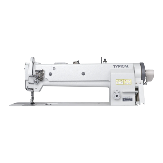
- Page 1 GC20606-D2 GC20606-1-D2 GC20606L18-D2T GC20606-1L18-D2T GC20606HL18-D2T GC20606-1HL18-D2T 2/1- Needle Compound Feed Lockstitch Sewing Machine With Automatic Thread Trimmer OPERATION INSTRUCTION / PARTS MANUAL...
- Page 2 Please don't adjust and repair the machine by non-professionals,except adjusting stitch. Specifications subject to change without notice TYPICAL SEWING MACHINE WANPING MACHINERY CO.,LTD. ADD: WANPING TOWN, WUJIANG CITY, JIANGSU PROVINCE, CHINA TEL: +86-512-63391278 FAX: +86-512-63391371 POST. CODE: 215223 Http://www.typicalwpchina.com E-mail:export@typicalwpchina.com...
-
Page 3: Brief Introduction
2. Main specifications 1. Brief Introduction The models adopt double (single) needle and two (single) GC20606 GC20606 Model GC20606 GC20606 vertical hooks with auto lubrication for thread looping, L18-D2T -1L18-D2T -1-D2 Specifications /HL18-D2T /-1HL18-D2T sliding lever for thread take up to form two lines of Application Medium and heavy duty lockstitch seam. - Page 4 3.1.4 Knee control presser foot lifter installation (Fig.3) a. Installation Install the Connector A, Bell crank B, Bell C in the order shown in Fig.3. B. Adjustment (Fig.4) 1. When the presser foot is at its lowest position, keep the crank in the position shown by b in the figure; turn the knee control stop adjusting screw C to touch with the oil reservoir, and tighten the nut of screw C.
- Page 5 3.1.7 Connecting the clutch lever to the pedal (Fig.7) a. The optimum tilt angle of pedal with floor is 20~30 degreee. b. Adjust the clutch of the motor so that clutch lever 10~12mm C and draw bar B run in line. c.
-
Page 6: Operation
b. When the machine starts for the initial time or resuse after a long period of time, the proper oil amout should be filled in sections of machine shown by arrows in Fig 10,11. When it is in operation, observe the oil sparking in oil screen to check the oil condition (Fig.12). - Page 7 4.2 Connecting the control box (Fig.15) Note: 4.2.1 When connecting or removing the connector, turn off the power to ensure safety. 4.2.2 The model must match with the control box of the motor. Table cutout Operation 4.3 Adjusting the stop position of the needle (Fig.16, 17)...
- Page 8 4.4 Coordination between needle, thread and sewing material Please apply needle DP×17, Nm125-180. The coarseness of needle should be in accordance with the nature of material. If stitch on heavy duty material with a slim needle, the needle will be easily bent. Skip or thread breakage may also occur.
- Page 9 4.7 Threading (Fig.20) The thread should be drawn through thread hole A, when light and smooth thread (polyester or long silk thread) is applied, it should be drawn through hole B. Keep the L3' L3 L2' L2 thread take-up lever at its highest position, draw the thread in numerical order.
-
Page 10: Machine Adsjustment
4.9 Installing the bobbin (Fig.22) Note: when the bobbin is installed into the bobbin case, the thread should be wound properly in the correct Thread direction shown in the figure. Slide plate Rotating hook Slide plate Rotating hook 4.10 Threading the bobbin thread (Fig.23) a. - Page 11 a.If the stiich form is the same as shown in Fig.24b, it indicates that the needle thread is too tight or the bobbin thread is too loose. Turn the thread tension screw counter clockwise to release the needle thread tension, or turn the adjusting screw with a screwdriver to increase the bobbin thread tension (Fig.25.26).
- Page 12 5.3.2 Resetting the safety clutch device a. While pressing down the button in the bed surface with left hand, turn the balance wheel slowly with right hand in the direction shown in Fig.29. b. When the stop plate stops the balance wheel, more strength is required to turn the balance wheel to reset the safety clutch device.
- Page 13 5.3.5 Presser foot lift volume adjustment (Fig.32) When stitch on the very elastic material or the thickness of the sewing material is changed. The adjustment should be done in the following order: Loosen the special bolt; When the centerline distance between the special bolt and the presser foot lift rear crank is decreased, the Crank Increase...
- Page 14 5.4.2 Adjusting the clearance between the movable knife and the rotating hook position block. (Fig.35) Screw A a. Turn the balance wheel to lower the needle bar to its Movable knife Screw B lowest position. b. Press down the trimming driven crank and turn the balance wheel, so that the movable knife can go forward as far as it can go.
- Page 15 5.7 Adjusting the trimming pressure of the movable knife and fixed knife (Fig.38) a. Loosen the set screw A. Fixed knife bracket b. Turn the adjusting screw B to adjust the trimming tension between the movable knife and the fixed knife. After adjustment, tighten the screw A.
-
Page 16: Arm Parts
1.Arm parts 9 10 49 50 55 56 65 66 70 71 72... - Page 17 1W F 1 - 0 4 3 Screw 1W F 3 - 0 2 5 Note: #1 only used for GC20606-D2; #2 only used for GC20606-1-D2; #3 only used for GC20606L18-D2T; #4 only used for GC20606-1L18-D2T; #5 only used for GC20606HL18-D2T;...
- Page 18 1.Arm parts 9 10 49 50 55 56 65 66 70 71 72...
- Page 19 84 W F 1 - 0 2 0 Screw #1、#3、#5 Note: #1 only used for GC20606-D2; #2 only used for GC20606-1-D2; #3 only used for GC20606L18-D2T; #4 only used for GC20606-1L18-D2T; #5 only used for GC20606HL18-D2T; #6 only used for GC20606-1HL18-D2T.
-
Page 20: Upper Shaft And Presser Foot Parts
2. Upper shaft and presser foot parts 39 40 37 38 16 17 55 56... - Page 21 43 W F 2 - 0 0 3 #3、#4、#5、#6 Middle bushing Note: #1 only used for GC20606-D2; #2 only used for GC20606-1-D2; #3 only used for GC20606L18-D2T; #4 only used for GC20606-1L18-D2T; #5 only used for GC20606HL18-D2T; #6 only used for GC20606-1HL18-D2T.
-
Page 22: Needle Bar And Lower Feed Parts
3. Needle bar and lower feed parts 5 6 7 8 9 10 12 13 43 45 46 47 48 49 84 85 86 GC20606/L18-D2 36 37 GC20606-1/-1L18-D2 75 76 59 61 64 65... - Page 23 Connecting screw 1W F 5 - 0 0 2 Right crank Note: #1 only used for GC20606-D2; #2 only used for GC20606-1-D2; #3 only used for GC20606L18-D2T; #4 only used for GC20606-1L18-D2T; #5 only used for GC20606HL18-D2T; #6 only used for GC20606-1HL18-D2T.
- Page 24 3. Needle bar and lower feed parts 5 6 7 8 9 10 12 13 43 45 46 47 48 49 84 85 86 GC20606/L18-D2 36 37 GC20606-1/-1L18-D2 75 76 59 61 64 65...
- Page 25 GB/T 95 6 SM1/8"×40/7 #1、#3、#5 #2、#4、#6 SM1/8"×44/4 Note: #1 only used for GC20606-D2; #2 only used for GC20606-1-D2; #3 only used for GC20606L18-D2T; #4 only used for GC20606-1L18-D2T; #5 only used for GC20606HL18-D2T; #6 only used for GC20606-1HL18-D2T. SM1/8"×40/13.5 ( ) quantity for GC20606-1-D2、 GC20606-1L18-D2T、 GC20606-1HL18-D2T.
-
Page 26: Lower Shaft And Thread Looping Parts
4. Lower shaft and thread looping parts 31 32 34 35 42 43 44 45 47 48 51 52 58 59 53 54... - Page 27 Washer 42 W F 5 - 0 0 5 Screw Note: #1 only used for GC20606-D2; #2 only used for GC20606-1-D2; #3 only used for GC20606L18-D2T; #4 only used for GC20606-1L18-D2T; #5 only used for GC20606HL18-D2T; #6 only used for GC20606-1HL18-D2T.
-
Page 28: Automatic Reverse Feed And Testing Parts
5. Automatic reverse feed and testing parts 36 37 30 31 53 54... - Page 29 #1,#2 43WF4-002 Screw #3,#4,#5,#6 Note: #1 only used for GC20606-D2; #2 only used for GC20606-1-D2; #3 only used for GC20606L18-D2T; #4 only used for GC20606-1L18-D2T; #5 only used for GC20606HL18-D2T; #6 only used for GC20606-1HL18-D2T. ( ) quantity for GC20606-1-D2、 GC20606-1L18-D2T、 GC20606-1HL18-D2T.
- Page 30 5. Automatic reverse feed and testing parts 36 37 30 31 53 54...
- Page 31 Washer 21 W F 3 - 0 2 6 GB/T97.1 Note: #1 only used for GC20606-D2; #2 only used for GC20606-1-D2; #3 only used for GC20606L18-D2T; #4 only used for GC20606-1L18-D2T; #5 only used for GC20606HL18-D2T; #6 only used for GC20606-1HL18-D2T.
-
Page 32: Thread Releasing And Auto-Trimming Parts
6. Thread releasing and auto-trimming parts 29 30 36 37 61 62 63 64 65 69 70 9 10 11 12... - Page 33 #1,#3,#5 22 T 7 - 0 0 8 #1,#3,#5 Note: #1 only used for GC20606-D2; #2 only used for GC20606-1-D2; #3 only used for GC20606L18-D2T; #4 only used for GC20606-1L18-D2T; #5 only used for GC20606HL18-D2T; #6 only used for GC20606-1HL18-D2T.
- Page 34 6. Thread releasing and auto-trimming parts 29 30 36 37 61 62 63 64 65 69 70 9 10 11 12...
- Page 35 Nail Washer 22 T 1 - 0 0 7 Note: #1 only used for GC20606-D2; #2 only used for GC20606-1-D2; #3 only used for GC20606L18-D2T; #4 only used for GC20606-1L18-D2T; #5 only used for GC20606HL18-D2T; #6 only used for GC20606-1HL18-D2T.
-
Page 36: Knee Control Presser Foot Lift Parts
7. Knee control presser foot lift parts 54 55 56 39 40 41... - Page 37 #3 , # 4 , # 5 , # 6 Washer #1 , # 2 #1,#2 SM5/16"×25/10 Note: #1 only used for GC20606-D2; #2 only used for GC20606-1-D2; #3 only used for GC20606L18-D2T; #1 , # 2 #4 only used for GC20606-1L18-D2T; #5 only used for GC20606HL18-D2T;...
-
Page 38: Winding Componcnt
8. Winding component (GC20606L18-D2T/-1L18-D2T/HL18-D2T/-1HL18-D2T) 20 21... - Page 39 13 W F 6 - 0 2 4 Screw Washer 3.5 GB896-86 Note: #1 only used for GC20606-D2; #2 only used for GC20606-1-D2; #3 only used for GC20606L18-D2T; #4 only used for GC20606-1L18-D2T; #5 only used for GC20606HL18-D2T; #6 only used for GC20606-1HL18-D2T.
-
Page 40: Lubrication Parts
9. Lubrication parts 20 21... - Page 41 1W F 6 - 0 1 5 Set clamp #1,#3,#5 Note: #1 only used for GC20606-D2; #2 only used for GC20606-1-D2; #3 only used for GC20606L18-D2T; #4 only used for GC20606-1L18-D2T; #5 only used for GC20606HL18-D2T; #6 only used for GC20606-1HL18-D2T.
-
Page 42: Foot Lifter Part (Gc20606L18-D2T/-1L18-D2T/Hl18-D2T/-1Hl8-D2T)
(GC20606L18-D2T/ L18-D2T/HL18-D2T/-1HL18-D2T) 10.Foot lifter part No . Part Number Name Remark 45 W F 6 - 0 0 3 Pneumatic pump 45 W F 7 - 0 0 1 Plate 93 W F 2 2 - 0 0 6 Adoptor 52 W F 5 - 0 0 3 Screw 43 W F 3 - 0 1 - D A... -
Page 43: Accessory
11. Accessory... - Page 44 Screw GB5282 ST4.8×19 Washer GB/T95 6 Note: #1 only used for GC20606-D2; #2 only used for GC20606-1-D2; #3 only used for GC20606L18-D2T; #4 only used for GC20606-1L18-D2T; #5 only used for GC20606HL18-D2T; #6 only used for GC20606-1HL18-D2T. ( ) quantity for GC20606-1-D2、 GC20606-1L18-D2T、 GC20606-1HL18-D2T.
-
Page 45: Table Of Contents
Content Operation Instruction 1. Brief introduction..................1 2. Main specifications..................1 3. Installation and preparation.................1-4 4. Operation....................4-8 5.Machine adsjustment..................5-13 Parts Manual 1. Arm parts....................14-17 2. Upper shaft and presser foot parts............18-19 3. Needle bar and lower feed parts..............20-23 4. Lower shaft and thread looping parts............24-25 5. - Page 46 Operation Instruction...
- Page 47 Parts Manual...
Need help?
Do you have a question about the GC20606-D2 and is the answer not in the manual?
Questions and answers
how to set the walking dog with the timimg
To set the timing on the Typical GC20606-D2 walking dog, follow these steps:
1. Turn the balance wheel to lower the needle bar to its lowest position.
2. Adjust the trimming cam:
- Press down the trimming driven crank so the trimming roller enters the trimming cam groove.
- Turn the balance wheel until the white mark on the balance wheel aligns with the position mark on the arm.
- Loosen the two set screws on the trimming cam and rotate it to align the marks, then tighten the screws.
3. Adjust the upper feed if needed:
- Loosen the special bolt on the horizontal feed crank.
- Move the bolt upward to reduce upper feed or downward to increase it.
- Position it on the reference line for correct timing.
These adjustments ensure the feed mechanism (walking dog) moves in sync with the needle and other parts.
This answer is automatically generated
My machine keeps going out of timing and I cant get the proper stitching
To fix timing issues and improve stitching on a Typical GC20606-D2 machine, follow these steps:
1. Check the Timing Wheel: Ensure the timing wheel (part 1WF2-027 or 1WF2-043) is properly aligned and securely fastened.
2. Inspect the Needle Bar: Verify the needle bar and lower feed parts are properly installed and moving smoothly.
3. Adjust the Hook Timing: The machine uses vertical hooks for thread looping. Adjust the hook so it meets the needle at the correct moment when the needle is at its lowest position.
4. Verify the Feed Mechanism: Ensure the compound feed system is synchronized and the feed dogs are moving correctly to avoid uneven stitches.
5. Lubricate Moving Parts: Use the plunge oil pump lubrication system to keep the upper and lower shafts running smoothly.
6. Check Belt Tension: The synchronic belt should be properly tensioned to ensure smooth operation.
7. Tighten Screws and Bushings: Ensure all screws, bushings, and rotating shafts are secure to prevent misalignment.
If issues persist, seek professional service, as non-professionals should not attempt advanced repairs.
This answer is automatically generated