
Related Manuals for typical GC20616


Summary of Contents for typical GC20616
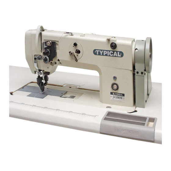
- Page 1 GC20616 Single Needle Upper and Lower Roller Feed Needle Feed Lockstitch Sewing Machine OPERATION INSTRUCTION / PARTS MANUAL...
- Page 2 Please don't adjust and repair the machine by non-professionals,except adjusting stitch. Specifications subject to change without notice TYPICAL SEWING MACHINE WANPING MACHINERY CO.,LTD. ADD: WANPING TOWN, WUJIANG CITY, JIANGSU PROVINCE, CHINA TEL: +86-512-63391278 FAX: +86-512-63391371 POST. CODE: 215223 Http://www.typicalwpchina.com E-mail:export@typicalwpchina.com Please don't adjust and repair the machine by non-professionals,except adjusting stitch.
-
Page 3: Table Of Contents
CONTENTS Operation Instruction 1. Brief introduction....................1 2.Main technical specifications................1 3. Preparation ....................1 4. Installing the machine head................1 5. Installing the motor..................2 6. Connecting the cluth lever to the pedal ..............2 7. Installing the oil reservoir................2 8. Installing the knee control lifter................3 9. -
Page 4: Brief Introduction
1. Brief introduction 2. Main technical specifications GC20616 adopts link thread take-up,driven roller poresser Application Medium and heavy duty materials foot, and timing feed of roller and needle. Vertical hooks 2500r.p.m Max.sewing speed for threading looping forms lockstitch seam. The upper... -
Page 5: Installing The Motor
5. Installing the motor (Fig.2) Align the machine balance wheel belt groove A with the motor pulley groove B by moving the motor C leftward and rightward. Be sure the belt is not touch with the table. 6. Connecting the clutch lever to the pedal(Fig.3) 1. -
Page 6: Installing The Knee Control Lifter
8. Installing the knee control lifter (Fig.5) Insert the assembled knee control lifter mechanism into the bottom connector A of the machine head, then tighten the stud screw C. Position of the bell could be adjusted by the operator to ensure easy operation,slight tension and proper swing range. -
Page 7: Winding The Bobbin Thread
11. Winding the bobbin thread (Fig.8) Install the bobbin B to the winder shaft. Thread A should pass through the center of the two tension discs E, then wind the tip of the thread a few turns around the bobbin B. Open the stop latch thumb lever D vertically so that the spring plate C is pressing upon the bobbin B. -
Page 8: First Sewing
14. First sewing (Fig.11) 1. Lift the presser foot lever; 2. Close the rooler foot; 3. Lay down the material; 4. Turn the balance wheel to make the needle pass through the material to be sewn; 5. Lower the presser foot lever. 1 0 0 mm When first sewing, the needle must be drawn out approx 100mm. -
Page 9: Adjusting The Tension Of Bobbin Thread And Needle Thread
17.Adjusting the tension of bobbin thread and needle thread(Fig.14) Normal stitch form should be as shown in Fig.14 A. When abnormal stitches occur with puckering or thread breakage,the tension of bobbin thread and needle thread should be adjusted accordingly. 1.If the stiches are as shown I Fig.14 B,which means that the tension of the needle thread is too strong or the tension of the bobbin thread is too weak,turn the tension regulating thumb nut counter clockwise to... -
Page 10: Adjusting The Tension Of The Roller Foot
19.Adjusting the tension of the roller foot Fig.16 ( ) Clockwise Counter clockwise The tension of the roller foot should be adjusted according to the thickness of the material. If sewing heavy material, strengthen the tension of the roller foot by turning the adjusting screw on the back of the machine head clockwise as shown in Fig.16;... -
Page 11: Position Between The Rotating Hook And The Needle
21.Position between the rotating hook and the needle (Fig.18) 1.6mm Hook point When the hook point is lifted by 1.8mm from its lowest Upper end of position, the position of the needle and the rotating hook is the needle eye as shown in Fig.18: Lowerend of 1.The upper end of the needle eye is... -
Page 12: Adjusting The Clearance Between The Hook Point And The Needle
24.Adjusting the clearance between the hook point and the needle (Fig.21) The clearance between the hook point and the needle should be approx 0.05mm.The clearance has been adjusted before delivery and it can only be re-adjusted when the needle is changed. 1.Lay down the machine head;... -
Page 13: Arm And Bed
1.Arm and bed 30 3 1... - Page 14 1.Arm and bed Part Number Name Remark Face plate Face plate 1 3 W F 2- 00 4 1 3 W F 2- 00 4 Screw(big) Screw(big) 1 3 W F 2- 00 5 1 3 W F 2- 00 5 Screw(small) Screw(small) 1 3 W F 2- 00 6...
-
Page 15: Thread Tension Parts
2.Thread tension parts 32 33... - Page 16 2.Thread tension parts Part Number Name Remark Thread guide pin Thread guide pin 1 3 W F 2- 06 6 1 3 W F 2- 06 6 1 3 W F 2- 06 7 1 3 W F 2- 06 7 Middle thread guide Middle thread guide 1 3 W F 2- 01 6...
-
Page 17: Upper Shaft And Thread Take-Up Lever Parts
3.Upper shaft and thread take-up lever parts 1 9 20 1 4 1 5 9 10 11 12... - Page 18 3.Upper shaft and thread take-up lever parts Part Number Name Remark Thread take-up link 1 3 W F 1- 03 0 1 3 W F 1- 03 0 Washer Needle bearing retainer 1 3 W F 1- 03 1 1 3 W F 1- 03 1 Thread take-up link needle bearing Thread take-up pin 1 3 W F 1- 03 2...
-
Page 19: Needle Bar Vibrating Parts
4.Needle bar vibrating parts 24 25 45 4 6... - Page 20 4.Needle bar vibrating parts Part Number Name Remark Upper feed shaft Upper feed shaft 1 3W F3-001 1 3W F3-001 Spacer Spacer 1 3W F3-002 1 3W F3-002 Needle bearing retainer Needle bearing retainer 1 3W F1-073 1 3W F1-073 Upper feed shaft bearing Upper feed shaft bearing Needle bearing bushing...
-
Page 21: Feed Mechanism Parts
5.Feed mechanism parts 1 5 1 6 1 9 2 0 37 38 39 40 41... - Page 22 5.Feed mechanism parts Part Number Name Remark Retainer 13WF 3 - 0 0 2 13WF 3 - 0 0 2 Spacer 13WF 1 - 0 7 3 13WF 1 - 0 7 3 Retainer Lower feed shaft bearing Lower feed shaft bearing Bushing for lower shaft bearing Bushing for lower shaft bearing 13WF 1 - 0 7 2...
-
Page 23: Presser Bar Lift Parts
6.Presser bar lift parts 34 35... - Page 24 6.Presser bar lift parts Part Number Name Remark Rubber plug 1 3 W F 1- 07 6 1 3 W F 1- 07 6 Bushing for presser bar 1 3 W F 4- 03 2 1 3 W F 4- 03 2 Screw 1 3 W F 3- 06 0 1 3 W F 3- 06 0...
-
Page 25: Upper Roller Feed Parts
7.Upper roller feed parts... -
Page 26: Upper Roller Feed Parts
7.Upper roller feed parts Part Number Name Remark Driving link assembly Driving link assembly 1 3WF3- 034 1 3WF3- 034 Screw Screw 1 3WF3- 038 1 3WF3- 038 Felt Felt 1 3WF3- 037 1 3WF3- 037 Driving dog Driving dog 1 3WF3- 036 1 3WF3- 036 Screw... -
Page 27: Rock Shaft And Thread Looping Parts
8.Rock shaft and thread looping parts 20 21 55 5 6... -
Page 28: Rock Shaft And Thread Looping Parts
8.Rock shaft and thread looping parts Part Number Name Remark Rock shaft(front) 72WF 1 -0 01 72WF 1 -0 01 Rock shaft(rear) 72WF 1 -0 02 72WF 1 -0 02 Rock shaft connector 13WF 1 -0 03 13WF 1 -0 03 Screw 13WF 1 -0 04 13WF 1 -0 04... - Page 29 9.Lurication parts 2526 3 3 34...
-
Page 30: Lubrication Parts
9.Lubrication parts Part Number Name Remark Oil pump Oil pump 72 WF5-001 72 WF5-001 Screw Screw 72 WF5-002 72 WF5-002 Felt Felt 72 WF5-003 72 WF5-003 Position screw Position screw 72 WF5-004 72 WF5-004 Spring Spring 72 WF5-005 72 WF5-005 Plunger Plunger 72 WF5-006... -
Page 31: Thread Winding Parts
10. Thread winding parts... - Page 32 10. Thread winding parts Part Number Name Remark 1 3 W F 6- 02 7 1 3 W F 6- 02 7 Tension thread guide plate 1 3 W F 2- 00 8 1 3 W F 2- 00 8 Screw 1 3 W F 4- 02 7 1 3 W F 4- 02 7...
-
Page 33: Accessories
11. Accessories 1 3 14... -
Page 34: Accessories
11. Accessories Part Number Name Remark 3 3 T F -0 11 3 3 T F -0 11 Oil pot 4 F - 0 07 4 F - 0 07 Spool stand complete 1 6 W F 5- 00 7 1 6 W F 5- 00 7 Bed leg 1 3 W F 7- 00 3...
Need help?
Do you have a question about the GC20616 and is the answer not in the manual?
Questions and answers