Table of Contents
Advertisement
Quick Links
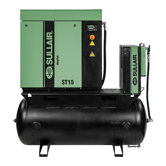
ST4, ST5, ST7, ST11, ST15
SAFETY WARNING
Users are required to read the
entire User Manual before han-
dling or using the product. Keep
the User Manual in a safe place
for future reference.
USER MANUAL
4 – 15 kW (5 – 20 hp)
Three-phase 60 Hz
WARRANTY NOTICE
Failure to follow the instructions
and procedures in this manual,
or misuse of this equipment, will
void its warranty.
Subject to EAR, ECCN EAR99 and related export control restrictions.
PART NUMBER:
88292018-236 R00
The information in this manual is current as of its
publication date and applies to compressor models
indicated on this cover with serial number:
37216100224
and all subsequent serial numbers until next revision of
this manual or release of a replacement manual.
Publication date: 03/31/2017
Copyright © 2017 Sullair, LLC. All rights reserved.
Advertisement
Table of Contents

Related Manuals for Sullair ShopTek ST4


Summary of Contents for Sullair ShopTek ST4
- Page 1 User Manual in a safe place void its warranty. Publication date: 03/31/2017 for future reference. Copyright © 2017 Sullair, LLC. All rights reserved. Subject to EAR, ECCN EAR99 and related export control restrictions.
- Page 2 Air Care Seminar Training Sullair Air Care Seminars are courses that provide hands-on instruction for the proper operation, maintenance, and servicing of Sullair products. Individual seminars on Stationary compressors and compressor electrical systems are offered at regular intervals throughout the year at Sullair’s training facility located at Michigan City, Indiana.
-
Page 3: Table Of Contents
ShopTek™ ST4, ST5, ST7, ST11, ST15 Three-phase 60 Hz User Manual Table of Contents Table of Contents Section 1: Safety.......................1 General....................... 1 Personal protective equipment ..............1 Pressure release ..................1 Fire and explosion ..................2 Moving parts ....................2 Hot surfaces, sharp edges and sharp corners.......... - Page 4 Table of Contents ShopTek™ ST4, ST5, ST7, ST11, ST15 Three-phase 60 Hz User Manual ID—ST4, ST5, ST7 ...................24 ID—ST11, ST15..................26 Piping and instrumentation—ST4, ST5, ST7 ..........28 Piping and instrumentation—ST11, ST15..........30 Section 4: Installation .................... 33 Compressor mounting—support and location........... 33 4.1.1 Outdoor installation (sheltered) ................
- Page 5 ShopTek™ ST4, ST5, ST7, ST11, ST15 Three-phase 60 Hz User Manual Table of Contents Replacement and alignment of belt pulleys..........50 6.9.1 Instructions for installing a pulley.................50 6.9.2 Instructions for removing a pulley ................50 6.10 Hose maintenance..................50 6.11 Tank mount package maintenance ............50 6.12 Troubleshooting..................
- Page 6 Table of Contents ShopTek™ ST4, ST5, ST7, ST11, ST15 Three-phase 60 Hz User Manual Notes: 88292018-236 R00 Subject to EAR, ECCN EAR99 and related export control restrictions.
-
Page 7: Section 1: Safety
1.1 General protective clothing, protective shields and barriers Sullair and its subsidiaries design and manufacture all of and electrical protective equipment, as well as noise their products so they can be operated safely. However,... -
Page 8: Fire And Explosion
1: Safety ShopTek™ ST4, ST5, ST7, ST11, ST15 Three-phase 60 Hz User Manual accordance with their manufacturer's recommenda- material. Any acoustical material with a protective tions. covering that has been torn or punctured should be replaced immediately to prevent accumulation of liq- E. -
Page 9: Hot Surfaces, Sharp Edges And Sharp Corners
ShopTek™ ST4, ST5, ST7, ST11, ST15 Three-phase 60 Hz User Manual 1: Safety E. Make sure all personnel are out of and/or clear of the DANGER compressor prior to attempting to start or operate it. F. Disconnect and lock out all power at source and ver- ify at the compressor that all circuits are de-energized to minimize the possibility of accidental start-up, or operation, prior to attempting repairs or adjustments. -
Page 10: Electrical Shock
1: Safety ShopTek™ ST4, ST5, ST7, ST11, ST15 Three-phase 60 Hz User Manual cover eyes to exclude light. Call a physician immedi- DANGER ately. All field equipment must be tested for electro- 1.8 Electrical shock static fields prior to servicing or making contact A. -
Page 11: Entrapment
ShopTek™ ST4, ST5, ST7, ST11, ST15 Three-phase 60 Hz User Manual 1: Safety J. Set compressor down only on a level surface capa- 1. Review the equipment or machine to be ble of safely supporting at least its weight and its locked and tagged out. -
Page 12: Safety Warnings
1: Safety ShopTek™ ST4, ST5, ST7, ST11, ST15 Three-phase 60 Hz User Manual lockout hasps on power shall remove pad- WARNING lock and lockout hasps and restore power. However, when the authorized person who applied the lock is unavailable to remove it Ground the unit following the instructions in this his/her Supervisor may remove padlock/pad- manual. - Page 13 State, Federal, and Do not touch any components on the circuit local electrical codes concerning isolation boards. Static voltage discharge may damage switches, fused disconnects, etc. Sullair pro- the components. vides a wiring diagram for use by the installer. NOTE Customer must provide electrical supply power disconnect within sight of machine.
- Page 14 1: Safety ShopTek™ ST4, ST5, ST7, ST11, ST15 Three-phase 60 Hz User Manual Notes: 88292018-236 R00 Subject to EAR, ECCN EAR99 and related export control restrictions.
-
Page 15: Section 2: Description
External piping, connectors, and the enclosure should be 2.1 Introduction inspected and maintained in accordance with the proce- The design of the Sullair ShopTek line of compressor dures and recommendations in this manual. units is a single stage, positive displacement, flooded rotary screw. - Page 16 2: Description ShopTek™ ST4, ST5, ST7, ST11, ST15 Three-phase 60 Hz User Manual 1. Fluid filter 7. E-stop button 2. Fluid cooler 8. Controller 3. Air inlet filter 9. Main motor 4. Separator tube 10. Compressor unit 5. Fluid fill sight glass 11.
- Page 17 ShopTek™ ST4, ST5, ST7, ST11, ST15 Three-phase 60 Hz User Manual 2: Description 1. Fluid filter 7. E-stop button 2. Aftercooler/fluid cooler 8. Controller 3. Air inlet filter 9. Main motor 4. Separator tube 10. Compressor unit 5. Fluid fill sight glass 11.
- Page 18 2: Description ShopTek™ ST4, ST5, ST7, ST11, ST15 Three-phase 60 Hz User Manual 1. Separator tube 5. Separator element 2. Cooler 6. Air 3. Fluid filter 7. Air/fluid mix 4. Compressor unit 8. Fluid Figure 2-3: Cooling/lubrication and discharge system—ST4, ST5, ST7 88292018-236 R00 Subject to EAR, ECCN EAR99 and related export control restrictions.
- Page 19 ShopTek™ ST4, ST5, ST7, ST11, ST15 Three-phase 60 Hz User Manual 2: Description 1. Separator tube 5. Separator element 2. Cooler 6. Air 3. Fluid filter 7. Air/fluid mix 4. Compressor unit 8. Fluid Figure 2-4: Cooling/lubrication and discharge system—ST11, ST15 88292018-236 R00 Subject to EAR, ECCN EAR99 and related export control restrictions.
-
Page 20: Compressor Cooling And Lubrication System-Functional Description
2: Description ShopTek™ ST4, ST5, ST7, ST11, ST15 Three-phase 60 Hz User Manual The compressed air/fluid mixture enters the separator/ 2.3 Compressor cooling and tube and flows through an internal baffle system that lubrication system—functional changes the flow’s direction and velocity, which causes description most of the fluid to fall to the bottom of the separator Refer to Figure 2-3 and Figure 2-4. -
Page 21: Control System-Functional Description
ShopTek™ ST4, ST5, ST7, ST11, ST15 Three-phase 60 Hz User Manual 2: Description 2.5 Control system—functional Full load mode—50 to 127 psig (3.4 to 8.8 bar) When the compressed air pressure rises above 50 psig description (3.4 bar), the minimum pressure valve opens allowing Refer to Figure 2-5 and Figure 2-6. - Page 22 2: Description ShopTek™ ST4, ST5, ST7, ST11, ST15 Three-phase 60 Hz User Manual 1. Air outlet 5. Separator tube 2. Unload solenoid valve 6. Pressure transducer 3. Air inlet 7. Controller 4. Minimum pressure/check valve 8. Check valve Figure 2-5: Control system—ST4, ST5, ST7 88292018-236 R00 Subject to EAR, ECCN EAR99 and related export control restrictions.
- Page 23 ShopTek™ ST4, ST5, ST7, ST11, ST15 Three-phase 60 Hz User Manual 2: Description 1. Air outlet 5. Separator tube 2. Unload solenoid valve 6. Pressure transducer 3. Air inlet 7. Controller 4. Minimum pressure/check valve Figure 2-6: Control system—ST11, ST15 88292018-236 R00 Subject to EAR, ECCN EAR99 and related export control restrictions.
-
Page 24: Air Inlet System, Functional Description
2: Description ShopTek™ ST4, ST5, ST7, ST11, ST15 Three-phase 60 Hz User Manual 2.6 Air inlet system, functional description 1. Air inlet filter 4. Clamp 2. Clamp 5. Compressor unit 3. Inlet tube Figure 2-7: Air inlet system—ST4, ST5, ST7 1. -
Page 25: Controller/Keypad
ShopTek™ ST4, ST5, ST7, ST11, ST15 Three-phase 60 Hz User Manual 2: Description 1. Run mode indicator light (green) 7. Return/reset button 2. Power on indicator light (red) 8. Cursor/confirm button 3. Fault warning indicator light (red) 9. Up button 4. -
Page 26: Led Lights
2: Description ShopTek™ ST4, ST5, ST7, ST11, ST15 Three-phase 60 Hz User Manual Refer to Figure 2-11. Press the Down arrow to display additional information about the compressor. The upper line will indicate the name of the temperature, pressure, LOAD PRESS: or other measurement. -
Page 27: Section 3: Specifications
ShopTek™ ST4, ST5, ST7, ST11, ST15 Three-phase 60 Hz User Manual 3: Specifications Section 3 Specifications 3.1 Tables of specifications—ShopTek 5 – 20 hp three-phase Table 3-1: Compressor specifications—60 Hz Model ST11 ST15 8.6 bar (125 psi)/ 8.6 bar (125 psi)/ 8.6 bar (125 psi)/ Rated pressure 10.3 bar (150 psi) 10.3 bar (150 psi) -
Page 28: Lubrication Guide
† Figure 3-1: Fluid fill location Sullube Key: A—1 year Refer to Figure 3-1 for the fluid fill port location. Sullair’s B—2,000 hours ShopTek series compressors are filled and tested at the C—4,000 hours ® factory with Sullube lubricant. - Page 29 ShopTek™ ST4, ST5, ST7, ST11, ST15 Three-phase 60 Hz User Manual 3: Specifications Notes: 88292018-236 R00 Subject to EAR, ECCN EAR99 and related export control restrictions.
-
Page 30: Id-St4, St5, St7
3.6 ID—ST4, ST5, ST7 88290017-299 R01... - Page 31 3.6 ID—ST4, ST5, ST7 Drawing notes EXHAUST AIR OUT AIR INLET INCOMING CUSTOMER POWER SUPPLY 1.96[50]DIA AIR OUT CONNECTION 3/4"NPT SERIAL PLATE HAND HOLD CONTAINMENT PAN DRAIN E-STOP CONTROLLER ALLOW 4.00 FEET [1.25 METERS] MINIMUM CLEARANCE AROUND MACHINE FOR ACCESS AND FREE CIRCULATION OF AIR. A FOUNDATION OR MOUNTING PACKAGE CAPABLE OF SUPPORTING THE WEIGHT OF THE PACKAGE, AND RIGID ENOUGH TO MAINTAIN THE COMPRESSOR FRAME LEVEL IS REQUIRED.
-
Page 32: Id-St11, St15
3.7 ID—ST11, ST15 88290017-300 R01... - Page 33 3.7 ID—ST11, ST15 Drawing notes EXHAUST AIR OUT AIR INLET INCOMING CUSTOMER POWER SUPPLY 1.96[50]DIA AIR OUT CONNECTION 3/4"NPT SERIAL PLATE HAND HOLD CONTAINMENT PAN DRAIN E-STOP CONTROLLER ALLOW 4.00 FEET [1.25 METERS] MINIMUM CLEARANCE AROUND MACHINE FOR ACCESS AND FREE CIRCULATION OF AIR. A FOUNDATION OR MOUNTING PACKAGE CAPABLE OF SUPPORTING THE WEIGHT OF THE PACKAGE, AND RIGID ENOUGH TO MAINTAIN THE COMPRESSOR FRAME LEVEL IS REQUIRED.
-
Page 34: Piping And Instrumentation-St4, St5, St7
3.8 Piping and instrumentation—ST4, ST5, ST7 88290016-646 R04... - Page 35 3.8 Piping and instrumentation—ST4, ST5, ST7 Key Part number Qty Description Notes 88290014-486 FILTER,AIR 80 CFM VALVE INLET 02250171-669 COMPRESSOR & PARTS,DXX063140A10ME50AB 88290014-534 TRANSDUCER,PT1000 GW100 PLT 88290015-814 TANK,WS4/5/7 88290015-049 ELEMENT,SEP WS708 88290014-222 GLASS,SIGHT M33 VALVE,THERMAL 185 DEG. F. ES11 88290015-765 COOLER,OIL WS4/5/7 88290014-484 ELEMENT,LUBE FLTR 5-20 HP...
-
Page 36: Piping And Instrumentation-St11, St15
3.9 Piping and instrumentation—ST11, ST15 88290015-826 R03... - Page 37 3.9 Piping and instrumentation—ST11, ST15 Key Part number Qty Description Notes 88290014-485 FILTER,AIR 80 CFM VALVE INLET 02250170-021 COMPRESSOR & PARTS,DXX087140E10M 88290014-534 TRANSDUCER,PT1000 GW100 PLT 88290014-226 TUBE,SEP WS11/15 88290015-567 ELEMENT, AIR/OIL SEP WS11/15+ 88290014-222 GLASS,SIGHT M33 02250078-204 VALVE,THERMAL 185 DEG. F. ES11 88290014-225 COOLER,COMB AC/OC WS11/WS15 88290014-484...
- Page 38 3: Specifications ShopTek™ ST4, ST5, ST7, ST11, ST15 Three-phase 60 Hz User Manual Notes: 88292018-236 R00 Subject to EAR, ECCN EAR99 and related export control restrictions.
-
Page 39: Section 4: Installation
32°F pressor frame level, and maintain the alignment of the (0°C). Contact Sullair Customer Care regarding compressor and motor. Tie-down bolts of sufficient size operation in sub-freezing temperatures. -
Page 40: Ventilation And Cooling
4: Installation ShopTek™ ST4, ST5, ST7, ST11, ST15 Three-phase 60 Hz User Manual 4.2 Ventilation and cooling NOTE Table 4-1: Ventilation requirements Housing the compressor in an inadequately ven- tilated enclosure will cause higher compressor Ventilation air required operating temperatures. Model 1040 1040... - Page 41 ShopTek™ ST4, ST5, ST7, ST11, ST15 Three-phase 60 Hz User Manual 4: Installation 1. Belt guard 3. Shipping studs (2) 2. Nut (2) Figure 4-2: Shipping studs—ST11, ST15 88292018-236 R00 Subject to EAR, ECCN EAR99 and related export control restrictions.
-
Page 42: Service Air Piping
Air lines from each individual com- pressor should be connected directly to the com- mon receiver tank. 1. Sullair compressor 5. Standard gate valve 2. Sullair dryer 6. By-pass gate valve 3. -
Page 43: Pipe Sizing
OSHA, National Electric where large demand fluctuations will occur. Code and/or any applicable local electrical codes apply- ing to isolation switches, fused disconnects, etc. Sullair 4.3.3 Isolation valves provides a wiring diagram for use by the installer. An... -
Page 44: Motor Rotation Direction Check
4: Installation ShopTek™ ST4, ST5, ST7, ST11, ST15 Three-phase 60 Hz User Manual 4.7 Motor rotation direction check 1. Main motor direction of rotation 2. Fan motor direction of rotation Figure 4-5: Main motor/fan motor direction of rotation—ST11, ST15 1. Main motor direction of rotation 2. -
Page 45: Section 5: Operation
ShopTek™ ST4, ST5, ST7, ST11, ST15 Three-phase 60 Hz User Manual 5: Operation Section 5 Operation 5.1 Routine operation Before starting the compressor, check the fluid level in WARNING the separator tube. If sight glass is not completely full, add the required amount of fluid to bring it to its proper High pressure hazard level. - Page 46 5: Operation ShopTek™ ST4, ST5, ST7, ST11, ST15 Three-phase 60 Hz User Manual Notes: 88292018-236 R00 Subject to EAR, ECCN EAR99 and related export control restrictions.
-
Page 47: Section 6: Maintenance
ShopTek™ ST4, ST5, ST7, ST11, ST15 Three-phase 60 Hz User Manual 6: Maintenance Section 6 Maintenance WARNING Before any repairs are attempted, refer to Sec- tion 1: Safety before proceeding. 6.1 General This compressor requires a minimal amount of inspec- tions and maintenance. -
Page 48: Every 4000 Hours Of Operation Or One Year (Whichever Occurs First)
6: Maintenance ShopTek™ ST4, ST5, ST7, ST11, ST15 Three-phase 60 Hz User Manual 6.5 Fluid filter maintenance 1. Fluid filter 2. Fluid sample valve Figure 6-3: Fluid filter assembly Refer to Figure 6-3. Replace the fluid filter under any of the following conditions, or whichever occurs first: •... -
Page 49: Air Filter Maintenance
ShopTek™ ST4, ST5, ST7, ST11, ST15 Three-phase 60 Hz User Manual 6: Maintenance 6.6 Air filter maintenance 1. Air filter element 2. Clamp 3. Hose Figure 6-4: Air filter assembly—ST4, ST5, ST7 1. Air filter element Refer to Figure 6-4 and Figure 6-5. Air filter maintenance should be performed every 2000 hours or sooner if nec- 2. -
Page 50: Separator Maintenance
6: Maintenance ShopTek™ ST4, ST5, ST7, ST11, ST15 Three-phase 60 Hz User Manual 6.7 Separator maintenance Replace the separator elements every 1 year or 4000 hours, whichever occurs first. The separator elements must be replaced. Do not attempt to clean and reinstall the separator elements. -
Page 51: Separator Element Replacement
ShopTek™ ST4, ST5, ST7, ST11, ST15 Three-phase 60 Hz User Manual 6: Maintenance The belt tension is achieved by raising the compressor 6.7.1 Separator element replacement unit which has the effect of increasing belt tension. Refer Refer to Figure 6-6 and Figure 6-7. Use the following pro- to Figure 6-10 and Figure 6-11. -
Page 52: Belt Tension Measurement With Frequency Meter
6: Maintenance ShopTek™ ST4, ST5, ST7, ST11, ST15 Three-phase 60 Hz User Manual 9. Average the three measurements to obtain give a false reading. As the probe detects a the true belt tension. vibration, the meter will display the fre- quency. - Page 53 ShopTek™ ST4, ST5, ST7, ST11, ST15 Three-phase 60 Hz User Manual 6: Maintenance 1. Belt guard 5. Comp. unit mounting plate bolts (4) 2. Belt tension adjustment screw 6. Comp. unit pulley 3. Locking nut 7. Belts 4. Jacking nut 8.
- Page 54 6: Maintenance ShopTek™ ST4, ST5, ST7, ST11, ST15 Three-phase 60 Hz User Manual 1. Belt guard 5. Comp. unit mounting plate bolts (4) 2. Belt tension adjustment screw 6. Comp. unit pulley 3. Locking nut 7. Belts 4. Jacking nut 8.
- Page 55 ShopTek™ ST4, ST5, ST7, ST11, ST15 Three-phase 60 Hz User Manual 6: Maintenance Table 6-1: Belt tension requirements TT Mini Optikrik Compressor First time Re-tension First time Re-tension Model Frequency (Hz) Frequency (Hz) Force (N) Force (N) ST4 series ST410 ST410 ST5 series ST510...
- Page 56 Misalignment of pulleys can cause rapid wear of the V-belt form, considerably shortening the service life of both belts and pulleys. Due to Sullair’s innovative design, only paral- lel alignment of the drive pulleys needs to be checked. Parallel alignment can be checked by two methods.
- Page 57 ShopTek™ ST4, ST5, ST7, ST11, ST15 Three-phase 60 Hz User Manual 6: Maintenance 6.12 Troubleshooting NOTE The information in the Troubleshooting Guide describes symptoms and usual causes for the listed discrepancies. However, do not assume that these are the only mal- For additional troubleshooting guidelines, con- functions or fault conditions that may occur.
- Page 58 6: Maintenance ShopTek™ ST4, ST5, ST7, ST11, ST15 Three-phase 60 Hz User Manual Table 6-3: Troubleshooting guide Symptom Probable cause Remedy Check service lines for leaks or open Air demand too high valves. Dirty air filter Replace filter. Check the control line bleed orifice Inlet valve bleed orifice obstructed/ inside the inlet valve for blockage or plugged...
- Page 59 Subject to EAR, ECCN EAR99 and related export control restrictions.
- Page 60 Sullair, LLC 3700 East Michigan Boulevard Michigan City, IN 46360 USA www.sullair.com 1-800-SULLAIR (USA only) 1-219-879-5451 (non-USA) Information and specifications are subject to change without prior notice. Subject to EAR, ECCN EAR99 and related export control restrictions.
Need help?
Do you have a question about the ShopTek ST4 and is the answer not in the manual?
Questions and answers