Sign In
Upload
Manuals
Brands
Sullair Manuals
Water Filtration Systems
ShopTek ST11
Sullair ShopTek ST11 Manuals
Manuals and User Guides for Sullair ShopTek ST11. We have
2
Sullair ShopTek ST11 manuals available for free PDF download: Operation & Maintenance Manual, User Manual
Sullair ShopTek ST11 Operation & Maintenance Manual (337 pages)
STATIONARY AIR COMPRESSOR
Brand:
Sullair
| Category:
Air Compressor
| Size: 20 MB
Table of Contents
Table of Contents
5
Chapter I Safety
7
Overview
7
Safety Equipment
7
Fire and Explosion Protection
7
Moving Parts
8
Hot Surfaces, Sharp Edges and Corners
8
Toxic and Irritative Substances
8
Electric Shock Protection
8
Hoisting and Transportation
9
Chapter II Compressor Structure
10
Overview
10
Drive System
17
Air Inlet System
18
Air Discharge System
19
Fluid Loop System
19
Cooling System
19
Fluid/Air Separator System
20
Airflow Regulation System
20
Microcomputer Controller
21
Chapter III Installation of Compressor
22
Groundwork and Placement of Unit
22
Cooling and Ventilation
22
Air Service
22
Checking Belt Drive
22
Checking Fluid Level
22
Checking Power Supply
22
Rotation Direction of Motor, Air End and Fan
23
Dismantlement of Transportation Fasteners
23
Chapter IV Compressor Operation
26
Safety Operation Procedure
26
Preparation before Initial Start-Up
26
Normal Operation
26
Stop
26
Warning
27
Chapter V Maintenance and Service
27
Overview
27
Dismantling and Installation of Enclosure
27
Downtime Maintenance and Pipeline Pressure Release
29
Daily Maintenance
30
Service after 50 Operation Hours
30
Service after Every 1000 Operation Hours
30
Service after Every 2000 Operation Hours
30
Service after Every 4000 Operation Hours
30
Changing Fluid
31
Service of the Air Filter
31
Maintenance of Fluid Filter and Thermal Valve Element
32
Maintenance of Fluid/Air Separator
33
Belt Tension Adjustment
34
Belt Tension Adjusting Methods
37
Pulley Installation and Adjustment
38
Maintenance of Minimum Pressure Valve
39
Check Valve
39
Maintenance of Solenoid Valve
40
Maintenance of the Motor
41
Chapter VI Electrical Schematic Diagram
43
Electrical Schematic Diagram of FULL-VOLT Unit
43
Electrical Schematic Diagram of Y-△ Unit
44
Chapter VII Troubleshooting
45
Overview
45
Possible Compressor Fault and Actions Are Listed in the Following Table
45
Chapter VIII Spare Parts List
47
Chapter IX Parts Manual
48
Motor-Compressor System Drawing-ST04, ST05, ST07
48
Motor-Compressor System Drawing -ST11, ST15
50
Air Discharge System-ST11, ST15
52
Fluid Loop System-ST04, ST05, ST07
53
Fluid Loop System-ST11, ST15
54
Cooling Fan System-ST04, ST05, ST07
55
Cooling Fan System-ST11, ST15
56
Fluid/Air Separation System-ST04, ST05, ST07
57
Fluid/Air Separation System-ST11, ST15
59
Acoustical Enclosure System-ST04, ST05, ST07
61
Acoustical Enclosure System-ST11, ST15
62
Control System-ST04, ST05, ST07
63
Control System-ST11, ST15
65
Chapter X EC Declaration
67
EC Declaration of Conformity
67
High-Efficiency
139
Warranty Notice
139
Safety Warning
139
Important Safety Instructions
168
Product Registration
170
Normal Sounds
170
Air Conditioner Features
171
Operating Instructions
172
Care and Cleaning
178
Energy Saving Ideas
178
Before You Call
179
Major Appliance Limited Warranty
180
Product Data Sheet
181
Important Safety Information
184
Safety and General Information
185
Battery Safety
185
Connect the Battery
186
Wall Mount Installation
187
Panel Features
188
Specifications
190
Status Indicators
192
Replace Battery
195
Troubleshooting
195
Warranty
198
Specifications and Accessories
203
Support & Resources
206
Selection Tables
207
Typical Performance Data
211
Safety Precautions
222
What's Included
224
Camera Overview
225
Status Indicator
226
Step One: Connect to the App
227
Camera Placement
228
Step Two: Place or Mount the Camera
229
Lorex Home App Overview
230
Clauses de Non-Responsabilité
234
Ce Qui Est Inclus
236
Vue D'ensemble de la Caméra
237
Indicateur D'état
238
Première Étape : Connexion à L'application
239
Placement de la Caméra
240
Deuxième Étape : Installer ou Monter la Caméra
241
Aperçu de L'application Lorex Home
242
Lo que Se Incluye
248
Descripción de la Cámara
249
Indicador del Estado
250
Paso Uno: Conectarse a la Aplicación
251
Colocación de la Cámara
252
Paso Dos: Coloque O Monte la Cámara
253
Descripción General de la Aplicación Lorex Home
254
Preliminary Note
261
1�1 Symbols Used
261
1�2 Warnings Used
261
Safety Instructions
262
Functions and Features
263
3�1 Pressure Equipment Directive (PED)
263
Function
264
4�1 Processing of the Measured Signals
264
4�2 Switching Output
265
4�3 Analogue Output
266
4�4 Consumed Quantity Monitoring [Imp]
268
4�4�1 Meter Reading
268
4�4�2 Counter Reset
268
4�4�3 Consumed Quantity Monitoring Via Pulse Signals
268
4�4�4 Consumed Quantity Monitoring Via Preset Counter
268
4�5 Measured Value Damping
270
4�6 Low Flow Cut-Off
270
4�8 Colour of the Characters in the Display
271
4�9�1 Additional Functions Via IO-Link
272
Installation
272
5�1 Installation Location
273
5�2 Installation Position
273
5�2�1 Inlet and Outlet Pipe Lengths
273
5�3 Installation in Pipes
274
Electrical Connection
275
Circuit Examples
276
Operating and Display Elements
277
Menu
278
8�1 Process Value Display (RUN)
278
8�2 Main Menu
279
8�3 Extended Functions
280
8�4 Submenu OUT1
281
8�5 Submenu OUT2
283
8�6 Submenu CFG
285
8�7 Submenus MEM, DIS
287
8�8 Submenus COLR, SIM
289
Set
291
Parameter Setting
291
10�1 Parameter Setting in General
292
10�1�2 Change to the Process Value Display (RUN Mode)
292
10�2 Settings for Volumetric Flow Monitoring
293
10�2�1 Limit Monitoring OUT1 or OUT2 / Hysteresis Function
293
10�2�2 Limit Monitoring OUT1 or OUT2 / Window Function
293
10�2�3 Analogue Signal Volumetric Flow OUT2
293
10�3 Settings for Consumed Quantity Monitoring
294
10�3�1 Quantity Monitoring by Pulse Signal OUT1 or OUT2
294
10�3�2 Quantity Monitoring by Preset Counter OUT1 or OUT2
294
10�3�5 Deactivation of the Counter Reset
294
10�4 Settings for Temperature Monitoring
295
10�4�3 Analogue Signal Temperature OUT2
295
10�5 Settings for Pressure Monitoring
296
10�5�3 Analogue Signal Pressure OUT2
296
10�6 User Settings (Optional)
297
10�6�1 Standard Display
297
10�6�9 Standard Conditions
298
10�6�10 Zero-Point Calibration Pressure
298
10�6�12 Switch-On /Switch-Off Delay
299
10�6�13 Error Behaviour of the Outputs
300
Restore Factory Setting
300
10�7 Diagnostic Functions
301
10�7�1 Read Min/Max Values
301
Operation
302
Error Correction
302
Maintenance, Repair and Disposal
304
Factory Setting
305
Pressure Transmitters
321
Technical Specifications
332
Dimensions (MM)
334
Advertisement
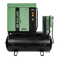
Sullair ShopTek ST11 User Manual (60 pages)
4 - 15 kW (5 – 20 hp) Three-phase 60 Hz
Brand:
Sullair
| Category:
Water Filtration Systems
| Size: 1 MB
Table of Contents
Table of Contents
3
Section 1: Safety
7
General
7
Personal Protective Equipment
7
Pressure Release
7
Fire and Explosion
8
Moving Parts
8
Hot Surfaces, Sharp Edges and Sharp Corners
9
Toxic and Irritating Substances
9
Electrical Shock
10
Lifting
10
Entrapment
11
Implementation of Lockout/Tagout
11
Safety Warnings
12
Section 2: Description
15
Introduction
15
Compressor Component Description
15
Compressor Cooling and Lubrication System-Functional Description
20
Compressor Discharge System-Functional Description
20
Control System-Functional Description
21
Air Inlet System, Functional Description
24
Controller/Keypad
25
LCD Display
25
LED Lights
26
Section 3: Specifications
27
Tables of Specifications-Shoptek 5 - 20 Hp Three-Phase
27
Lubrication Guide
28
Application Guide
28
Lubrication Change Recommendations and Fluid Filter and Separator
28
Maintenance
28
Installation Drawings (ID), Piping & Instrumentation Diagrams (P&I)
28
And Wiring Diagrams (WD)
28
ID-St4, St5, St7
30
ID-St11, St15
32
Piping and Instrumentation-ST4, ST5, ST7
34
Piping and Instrumentation-ST11, ST15
36
Section 4: Installation
39
Compressor Mounting-Support and Location
39
Outdoor Installation (Sheltered)
39
Ventilation and Cooling
40
Service Air Piping
42
Pipe Sizing
43
Auxiliary Receiver Tank
43
Isolation Valves
43
Fluid Containment
43
Belt Check
43
Fluid Level Check
43
Electrical Preparation
43
Motor Rotation Direction Check
44
Section 5: Operation
45
Routine Operation
45
Section 6: Maintenance
47
General
47
Maintenance after Initial 50 Hours of Operation
47
Maintenance Schedule
47
Every 2000 Hours of Operation or Six Months (Whichever Occurs First)
47
Every 2000 Hours of Operation or One Year (Whichever Occurs First)
47
Every 4000 Hours of Operation or One Year (Whichever Occurs First)
48
Every One Year
48
Every Two Years
48
Fluid Maintenance
48
Fluid Filter Maintenance
48
Fluid Filter Replacement
48
Air Filter Maintenance
49
Air Filter Element Replacement
49
Separator Maintenance
50
Separator Element Replacement
51
Belt Maintenance
51
Belt Tension Measurement with Optikrik Tension Meter
51
Belt Tension Measurement with Frequency Meter
52
Belt Tension Adjustment
52
Advertisement
Related Products
Sullair ShopTek ST4
Sullair ShopTek ST5
Sullair ShopTek ST7
Sullair ShopTek ST15
Sullair SXT
Sullair SXCS
Sullair SXF
Sullair SXH
Sullair SCD300
Sullair SCD400
Sullair Categories
Air Compressor
Dryer
Dehumidifier
Controller
Water Filtration Systems
More Sullair Manuals
Login
Sign In
OR
Sign in with Facebook
Sign in with Google
Upload manual
Upload from disk
Upload from URL