Table of Contents
Advertisement
Quick Links
A l l t e s t I n s t r u me n t s , I n c .
5 0 0 C e n t r a l A v e .
F a r mi n g d a l e , N J 0 7 7 2 7
P : ( 7 3 2 ) 9 1 9 - 3 3 3 9
F : ( 7 3 2 ) 9 1 9 - 3 3 3 2
a l l t e s t . n e t
s s a l e s @ a l l t e s t . n e t
T h e t e s t & me a s u r e me n t
e q u i p me n t y o u n e e d a t
t h e p r i c e y o u w a n t .
A l l t e s t c a r r i e s t h e w o r l d ' s l a r g e s t s e l e c t i o n o f
u s e d / r e f u r b i s h e d b e n c h t o p t e s t & me a s u r e me n t
e q u i p me n t a t 5 0 % t h e p r i c e o f n e w .
O O u r e q u i p me n t i s g u a r a n t e e d w o r k i n g , w a r r a n t i e d , a n d
a v a i l a b l e w i t h c e r t i f i e d c a l i b r a t i o n f r o m o u r i n - h o u s e s t a f f
o f t e c h n i c i a n s a n d e n g i n e e r s .
• 1 0 + f u l l t i me t e c h n i c i a n s w i t h o v e r 1 5 0 y e a r s o f
s p e c i a l i z a t i o n
• 9 0 d a y w a r r a n t y & 5 d a y r i g h t o f r e t u r n o n a l l
e q u i p me n t
• • 1 - 3 y e a r w a r r a n t i e s f o r n e w a n d
p r e mi u m- r e f u r b i s h e d e q u i p me n t
• E v e r y u n i t t e s t e d t o O E M s p e c i f i c a t i o n s
• S a t i s f a c t i o n g u a r a n t e e d
Y o u h a v e p l a n s , w e w i l l h e l p y o u a c h i e v e t h e m.
A n y p r o j e c t . A n y b u d g e t .
t
G e t a q u o t e t o d a y !
C C a l l ( 7 3 2 ) 9 1 9 - 3 3 3 9 o r e ma i l s a l e s @a l l t e s t . n e t .
Advertisement
Table of Contents

Subscribe to Our Youtube Channel
Related Manuals for Keithley 7701


Summary of Contents for Keithley 7701
- Page 1 T h e t e s t & me a s u r e me n t e q u i p me n t y o u n e e d a t t h e p r i c e y o u w a n t . A l l t e s t I n s t r u me n t s , I n c .
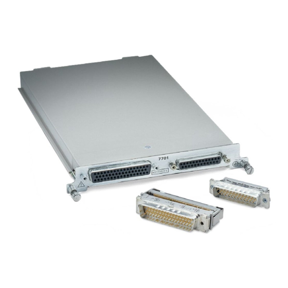
- Page 2 Model 7701 User’s Guide PA-769 Rev. A / 3-01 The Model 7701 can be used with Keithley Models 2700, 2701, and 2750. All references to the Models 2700/2750 also apply to the Model 2701. A G R E A T E R M E A S U R E O F C O N F I D E N C E...
-
Page 3: Limitation Of Warranty
WARRANTY Keithley Instruments, Inc. warrants this product to be free from defects in material and workmanship for a period of 1 year from date of shipment. Keithley Instruments, Inc. warrants the following items for 90 days from the date of shipment: probes, cables, rechargeable batteries, diskettes, and documentation. -
Page 4: Safety Precautions
Keithley products are designed for use with electrical signals that The instrument and accessories must be used in accordance with its are rated Installation Category I and Installation Category II, as de- specifications and operating instructions or the safety of the equip-... - Page 5 Keithley Instru- symbol on an instrument indicates that the user should re- ments. Standard fuses, with applicable national safety approvals, fer to the operating instructions located in the manual.
- Page 6 Model 7701 The information in this section is organized as follows: • Card configuration – schematic on page • Connections and wiring on page • Screw terminals on page • D-shell connectors on page • Wiring on page • Typical connections on page •...
-
Page 7: Card Configuration - Schematic
When connected to the internal DMM, all other mod- ules must be derated to 150VDC or 150Vrms (212V peak) for AC waveforms. NOTE The Model 7701 is shipped from the factory with the screw terminal jumpers NOT installed. See “Screw terminals” to install the jumpers. - Page 8 Section 2 of the Model 2700 or 2750 User’s Manual. Although the Model 7701 relays are the latching type (relays hold their state even after power has been removed), all relay states are set to open a few seconds after either a power cycle or an *RST command is issued.
-
Page 9: Dual Independent Multiplexers
Multiple channel operation allows the switching module to be configured as two independent mul- tiplexers. The Model 7701 is normally used as a single 1 × 32 multiplexer, but it can also be configured as two 1 × 16 multiplexers. - Page 10 Perform the following steps to internally connect the channels of the Model 7701 to the DMM of the Model 2700/2750: Remove the top cover of the Model 7701. It is secured to the module case by a single screw. Install the four supplied #22 AWG jumpers in the screw terminals as shown in Figure 3.
- Page 11 D-shell connectors Figure 4 shows the pin numbers for the Model 7701 rear panel connectors. The 50-pin D-shell is used to access channels 1 through 24, and Multiplexer 1 terminals. The 25-pin D-shell is used to access channels 25 through 32, and Multiplexer 2 terminals. The user-configurable screw terminals are also accessed at the 25- pin D-shell.
- Page 12 Any unused D-shell connector must have the connector cover installed. The Model 7701 is supplied with one 50-pin male IDC ribbon cable connector, and one 25-pin male IDC ribbon cable connector. These ribbon cable connectors mate to the D-shell connectors of the switching module.
- Page 13 Ch 11 Lo Violet Ch 24 Hi Orange Ch 12 Hi Grey Ch 24 Lo Yellow Ch 12 Lo White Mux 1 Hi Green Ch 13 Hi Black Mux 1 Lo *50-conductor IDC ribbon cable is available from Keithley, Part #15020.
- Page 14 Model 7701 Figure 5 50-conductor ribbon cable terminal identification 50-Pin D-Shell Male IDC IDC Ribbon Cable — 50-Conductor 1 Brown Ch 1 2 Red 3 Orange Ch 2 4 Yellow 5 Green Ch 3 6 Blue 7 Violet Ch 4...
- Page 15 Ch 30 Hi 6 Yellow Ch 30 Lo 19 Green Orange Ch 31 Hi 7 *25-conductor IDC ribbon cable is available from Keithley, Part #15025. Figure 6 25-conductor ribbon cable terminal identification 25-Pin D-Shell IDC Ribbon Cable — 25-Conductor Male IDC...
- Page 16 Model 7701 Figure 7 Connecting ribbon cable assembly KEITHLEY CONNECTOR COVER Warning: When using ribbon cable, Install plastic cover DO NOT exceed 42 volts over unused connector anywhere in the test system using two #4-40 screws. or at the front panel inputs of the Model 2700/2750.
-
Page 17: Typical Connections
Model 7701 Typical connections The following examples show typical wiring connections for the following types of measurements: Ω 2-Wire and thermistor connections, • Figure Ω 4-Wire and RTD connections, • Figure • Voltage connections (AC or DC), Figure Figure 9 Ω... -
Page 18: Connection Log
DC Voltage AC Voltage Column 1 (Columns 2 31) Column 32 Connection log Make a copy of Table 4 and affix it to the cover of the Model 7701. Use this to record connection infor- mation and channel descriptions as needed. - Page 19 Model 7701 Table 4 Connection log Model 7701 Channel Color Description Description Color Channel MUX 1 MUX 2 CH17 CH18 CH19 CH20 CH21 CH22 CH23 CH24 CH25 CH10 CH26 CH11 CH27 CH12 CH28 CH13 CH29 CH14 CH30 CH15 CH31 CH16...
-
Page 20: Channel Assignments
CH4 and CH20 CH8 and CH24 CH12 and CH28 CH16 and CH32 System channel operation for the Model 7701 is summarized as follows: • keys on the Model 2700 or 2750 DMM can be used to close a system channel. •... -
Page 21: Multiple Channel Operation
Multiple channel operation provides independent control of switching module channels. When you close a multiple channel, only the specified channel (or channels) will close. Other closed channels are not affected. Multiple channel operation for the Model 7701 is summarized as follows: •... - Page 22 Model 7701 Figure 12, channels 1 and 35 are closed to test DUT 1. The test for the other DUTs is similar except that different measurement channels are closed. Closed channels for each DUT test are listed as follows: Tested...
- Page 23 Figure 12. DMM LO Test procedure: NOTE The following test procedure assumes a Model 7701 switching module installed in slot 1 of the mainframe. Multiple channel operation from the front panel is not available for early versions of the Model 2700.
- Page 24 Biasing and measuring DUT (dual multiplexing) This application demonstrates how to use the Model 7701 as a dual multiplexer to bias and measure 16 DUT. An external source powers DUT, while the DMM of the Model 2700/2750 measures the output of the DUT.
- Page 25 Model 7701 Figure 14 Biasing and measuring DUT test system (multiple channel operation) Multiplexer 1 Ch 1 Note: Installation of the four screw terminal jumpers is shown. (Channels 2–15) Ch 35 Ch 16 Input Jumper Ch 33 (1 of 4)
- Page 26 Model 7701 Test procedure: NOTE The following test procedure assumes a Model 7701 switching module installed in slot 1 of the mainframe. Multiple channel operation from the front panel is not available for early versions of the Model 2700. Open all channels.
-
Page 27: Performance Verification
All service information is intended only for qualified service personnel. Do not attempt to service the Model 7701 unless you are qualified to do so. Performance verification Use the performance verification procedure for the Model 7701. This procedure is provided in PA-775 of this manual. Replaceable parts This section contains replacement parts information and the component layout drawing for the Model 7701. - Page 28 Model 7701 Table 5 Model 7701 parts list Keithley Part Circuit Designation Description C1, C3, C4, C9, C10, C11, C14 CAP, .1UF, 20%, 50V, CERAMIC (1206) C-418-.1 C2, C6, C17, C18, C19, C20, C23, C24, CAP, 47PF, 5%, 100V, CERAMIC (0805)
- Page 29 Model 7701 Table 5 (cont.) Model 7701 parts list Keithley Part Circuit Designation Description 4-40 X 7/16 STANDOFF ST-166-18 BOTTOM CARD COVER 7703-301B CHIPLOC BAG STATIC SHIELDING PO-13-1 D-SUB CABLE KIT 7709-306A DUAL CONN COVER 7709-312A FINAL INSPECTION 7701-FIN-51 HOLE SIZE...
- Page 30 Model 7701 Figure 15 Model 7701 component layout (Side-06) GND_D1 +5VD +5VM MC - 612 Primary Side Components (Side - 06) Note: For component information, see 7701 Product Structure.
- Page 31 Model 7701 Figure 16 Model 7701 component layout (Side-01) Secondary Side Components (Side - 01) Note: For component information, see 7701 Product Structure.
- Page 32 The Model 7701 is rated for low-voltage applications. Channel 32 150Vrms (212V peak) for AC waveforms, When connecting the 7701 to the internal DMM via the screw terminals, all other modules in the 1A switched, 60W, 125VA maximum. mainframe must be derated to 150VDC or 150Vrms (212V peak) for AC waveforms.
- Page 33 Specifications are subject to change without notice. All Keithley trademarks and trade names are the property of Keithley Instruments, Inc. All other trademarks and trade names are the property of their respective companies. Keithley Instruments, Inc. 28775 Aurora Road • Cleveland, Ohio 44139 • 440-248-0400 • Fax: 440-248-6168 1-888-KEITHLEY (534-8453) •...
Need help?
Do you have a question about the 7701 and is the answer not in the manual?
Questions and answers