Table of Contents
Advertisement
Quick Links
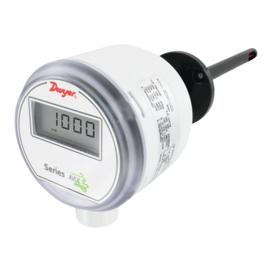
Series AVUL Air Velocity Transmitter with Modbus
Specifications - Installation and Operating Instructions
The Series AVUL Air Velocity Transmitter quickly and accurately measures air
velocity or volumetric flow in imperial or metric units. Simultaneous current and voltage
outputs on all models provide universal inputs to monitoring equipment while the
output range, units, and 0-5/10 VDC output can be configured via local DIP switches.
The optional integral display, or the portable remote display tool, provide a convenient
way to locally monitor process values and configure the unit.
Models are available in 3% and 5% accuracy models to suit a variety of needs, and the
optional BACnet MS/TP or Modbus
RTU/ASCII communication protocol allows units
®
to be daisy-chained while providing access to all of the velocity and flow data, as well
as additional information such as air temperature.
MODEL CHART
Model
AVUL -3 D A1 -LCD AVUL-3DA1-LCD
Accuracy
5
3
Mounting
D
Output
A1
B1
M1
Options
LCD
FC
NIST
GLD
SF
DWYER INSTRUMENTS, INC.
P.O. BOX 373 • MICHIGAN CITY, INDIANA 46360, U.S.A.
±(0.2 m/s + 5% of reading) @ standard
conditions
±(0.2 m/s + 3% of reading) @ standard
conditions
Duct mount
Analog universal (0-5 VDC, 0-10 VDC, 4-20
mA)
Analog + BACnet MS/TP
Analog + Modbus
RTU/ASCII
®
LCD display
Factory calibration certificate
NIST certificate
Electrical cable gland
Silicone free
3-49/64
1/2 NPS
[95.71]
2-43/64
[67.92]
3-33/64
7-41/64
[89.13]
[194.07]
7-17/64
[184.60]
39/64
[15.32]
SPECIFICATIONS
Service: Clean air and non-combustible, compatible gases.
Wetted Materials: Consult factory.
Range: 1000, 2000, 3000, 4000 FPM (5, 10, 15, 20 m/s); Field selectable.
Accuracy: ±(5% of reading + 0.2 m/s) or ±(3% of reading + 0.2 m/s) @ standard
conditions, depending on model.
Temperature Limits: 32 to 122°F (0 to 50°C).
Power Requirements: 24 VDC ±20% or 24 VAC ±20%.
Humidity Limits: 5 to 95% RH, non-condensing.
Output Signals: 4-20 mA, 0-5 VDC, 0-10 VDC.
Response Time (90%): 10 s, typical.
Zero and Span Adjustments: Digital push buttons.
Output Load Resistance: Current output: 0 to 1100 Ω max.; Voltage output:
Minimum load resistance 1 kΩ.
Current Consumption: 60 mA max.
Display (Optional): 5 digit LCD.
Electrical Connections (Analog): Power and output: 4-wire removable European
style terminal block for 16 to 26 AWG.
Communication (Optional): Connections: BACnet MS/TP or Modbus
3-wire removable European style terminal block for 16 to 26 AWG; Supported baud
rates: 9600, 19200, 38400, 57600, 76800, 115200.
Device Load: 1/8 unit load.
Electrical Entry: 1/2˝ NPS thread. Accessory (A-151): Cable gland for 5 to 10 mm
diameter cable.
Enclosure Rating: NEMA 4X (IP66).
Mounting Orientation: Flow direction must be parallel to the sensor tip;
See Installation section for details.
Weight: 6.0 oz (160 g).
Agency Approval: CE.
Phone: 219-879-8000
Fax: 219-872-9057
Bulletin P-AVUL-M
Communication
®
3-3/16
[80.81]
1-19/32
[40.59]
31/32 [24.58]
2-5/32
[54.82]
Ø15/32
[11.84]
RTU/ASCII:
®
www.dwyer-inst.com
e-mail: info@dwyermail.com
Advertisement
Table of Contents

Related Manuals for Dwyer Instruments AVUL Series


Summary of Contents for Dwyer Instruments AVUL Series
- Page 1 See Installation section for details. NIST NIST certificate Weight: 6.0 oz (160 g). Electrical cable gland Agency Approval: CE. Silicone free DWYER INSTRUMENTS, INC. Phone: 219-879-8000 www.dwyer-inst.com P.O. BOX 373 • MICHIGAN CITY, INDIANA 46360, U.S.A. Fax: 219-872-9057 e-mail: info@dwyermail.com...
-
Page 2: Installation
INSTALLATION Although low loop resistances are recommended, the absolute maximum current loop load resistance, R , is defined by the following the equation: Duct Mount: – 2.0) The transmitter should be mounted away from fans, corners, heating and cooling where V is the power supply voltage 0.02 coils, and other equipment that will effect the measurement of the air velocity. - Page 3 Simultaneous Current and Voltage Output Operation Setting the Air Velocity Range The range of the instrument is selected by using DIP switches 1 and 2 on SW1. Table DO NOT EXCEED SPECIFIED SUPPLY VOLTAGE RATINGS. CAUTION 1 shows the maximum full scale value for the selected range and unit. Refer to Setting PERMANENT DAMAGE NOT COVERED BY WARRANTY WILL the Engineering Units section for information on setting the unit.
-
Page 4: Programming Menus
CALIBRATION There is a 5 second delay from the time the zero or span calibration NOTICE buttons are released until the time that the change in calibration takes place. This delay is used to reduce vibration or disturbances of the user related to the button presses. -
Page 5: Appendix I: Air Velocity / Air Flow Calculations
MAINTENANCE/REPAIR Access Security Upon final installation of the Series AVUL Air Velocity Transmitter, no routine Level Setting View Menu Edit Menu Span Zero maintenance is required besides zeroing the transmitter occasionally. Besides routine calibration and installation of the LCD, the Series AVUL is not field serviceable, and it is not possible to repair the unit. -
Page 6: Appendix Iv: Programming Via Modbus
PWR GND IOUT VOUT D1[+] D0[-] COM APPENDIX IV: Programming Via Modbus Communication Protocol ® Modbus Mode Supported Baud Rates Data Size Parity Stop Bits ® 9600 Even 19200 TO PREVIOUS TO NEXT 38400 None DEVICE DEVICE 57600 None 76800 ASCII Even D1[+]... -
Page 7: Appendix V: Setting Modbus ® Communication Protocol Mac Address Of Unit
Coils The coil registers represent functions of the device. The value returned when reading a coil register indicates the status of the last function execution. If the value is 1, then the last time the function executed was a success. If the value is 0, then the function has either not been executed since power on or failed during the last execution. -
Page 8: Appendix Iii: Menu Flow Chart
APPENDIX III: Menu Flow Chart BUTTON PRESS LEGEND MENU CONVENTIONS IN HOME POSITION: ZERO = PRESS ZERO BUTTON CALIBRATE UNIT TO ZERO PRESSURE. ZERO = PRESS SPAN BUTTON SPAN DISPLAY IS NOT NECESSARY CALIBRATE UNIT TO SPAN PRESSURE. SPAN = PRESS AND HOLD ZERO BUTTON ZERO ZERO = PRESS AND HOLD SPAN BUTTON... - Page 9 Velocity Mode Menu FROM AVERAGING MENU SPAN ADJUST DISPLAY SPAN UPON RELEASE K FACTOR SPAN SELECT MAXIMUM OUTPUT SPAN UPON RELEASE SET BY PRESSURE OR VELOCITY SPAN INCREMENT ZERO DIGIT ADJUST VELOCITY SPAN UPON RELEASE OUTPUT HIGH SELECT SPAN DIGIT FPM OR M/S BASED ON DIP SWITCH SETTING INCREMENT...
- Page 10 Flow Mode Menu FROM AVERAGING MENU SPAN ADJUST DISPLAY SPAN UPON RELEASE K FACTOR SPAN INCREMENT ZERO DIGIT SPAN UPON RELEASE SELECT SPAN DIGIT SQ. FEET OR SQ. METERS BASED ON DIP SWITCH SETTING SPAN SELECT MAXIMUM OUTPUT SPAN UPON RELEASE SET BY PRESSURE OR FLOW SPAN...
- Page 11 Security Menu FROM "UPDATE SECURITY AND SAVE" MENU UPDATE SECURITY ZERO ZERO ZERO LEVEL ZERO SPAN SPAN SPAN SPAN SAVE CHANGES SPAN UPON RELEASE ZERO ZERO SPAN SPAN HOME POSITION...
- Page 12 __________________________________________________________________________________________________________________________________________ __________________________________________________________________________________________________________________________________________ __________________________________________________________________________________________________________________________________________ Modbus is a registered trademark of Schneider Automation, Inc. ® ©Copyright 2020 Dwyer Instruments, Inc. Printed in U.S.A. 11/20 FR# 444387-00 Rev. 2 DWYER INSTRUMENTS, INC. Phone: 219/879-8000 dwyer-inst.com P.O. BOX 373 • MICHIGAN CITY, INDIANA 46360, U.S.A.
Need help?
Do you have a question about the AVUL Series and is the answer not in the manual?
Questions and answers