
Subscribe to Our Youtube Channel
Related Manuals for Fike FCP-300


Summary of Contents for Fike FCP-300
- Page 1 Addressable Fire Alarm Control Panel FCP-300/FCP-300ECS Installation/Operation Manual Document LS10145-002FK-E 3/12/2021 P/N LS10145-002FK-E:A • ECN 151526...
- Page 2 Adequate written records of all rise feature of each detector should be tested at least once per year inspections should be kept. by a qualified fire protection specialist. Heat detectors are designed to Limit-F-2020 protect property, not life. FCP-300/FCP-300ECS Manual — P/N LS10145-002FK-E:A 3/12/2021...
- Page 3 Microsoft Corporation. Chrome™ and Google™ are trademarks of Google Inc. Firefox® is a registered trademark of The Mozilla Foundation. ©2021. All rights reserved. Unauthorized use of this document is strictly prohibited. FCP-300/FCP-300ECS Manual — P/N LS10145-002FK-E:A 3/12/2021...
- Page 4 • Brief description of content you think should be improved or corrected • Your suggestion for how to correct/improve documentation Send email messages to: FikeElectSupport@fike.com or call (800)979-3453, x21 in US or (816)229-3405 international FCP-300/FCP-300ECS Manual — P/N LS10145-002FK-E:A 3/12/2021...
-
Page 5: Table Of Contents
3.7.3: Maximum Battery Standby Load................................23 Section 4: Control Panel Installation ..........................24 4.1: Mounting the Control Panel Cabinet ................................24 4.1.1: Preventing Water Damage..................................24 4.1.2: Removing the FCP-300/ECS Assembly from the Housing........................24 4.1.3: Ethernet Connection .....................................24 4.2: AC Connection.........................................25 4.3: Battery Power ........................................25 4.3.1: RBB Accessory Cabinet ..................................26... - Page 6 6.3.2: Edit Voice Commands..................................65 6.4: Sync Network Options.....................................66 6.5: Network Management Quick Reference .................................67 Section 7: Fike and SWIFT SLC Device Installation..................... 69 7.1: List of Fike SLC Devices ....................................69 7.2: SWIFT Wireless SLC Devices ..................................69 7.3: Maximum Number of SLC Devices ................................69 7.4: Wiring Requirements for SLC Devices ................................69...
- Page 7 10.2.3: Single Key Acknowledge .................................113 10.3: Menu System .......................................113 10.3.1: Main Menu Overview..................................113 10.3.2: Using the Menus ....................................113 10.4: Basic Operation ......................................113 10.4.1: Setting Time and Date ..................................113 10.4.2: Disable / Enable a Point..................................113 FCP-300/FCP-300ECS Manual — P/N LS10145-002FK-E:A 3/12/2021...
- Page 8 11.7: Using the Microphone....................................130 11.7.1: Microphone Functionality ................................130 11.7.2: Custom ECS Event ...................................130 11.7.3: Fire Page ......................................130 11.8: Recording Custom Messages..................................131 11.8.1: Recording Messages 1-15 Using Aux Audio Input ..........................132 11.8.2: Recording Messages 1-15 Using the Microphone..........................133 FCP-300/FCP-300ECS Manual — P/N LS10145-002FK-E:A 3/12/2021...
- Page 9 11.9: Network Paging ......................................135 Section 12: Reporting ..............................136 12.1: Receivers Compatible with the Control Panel.............................136 12.2: SIA - FCP-300/ECS Panels PI Modifier Contact Reporting: ........................143 12.3: SIA – Panel Communicator: ..................................144 Section 13: Testing and Troubleshooting........................145 13.1: Troubleshooting ......................................145 13.2: Event History .......................................146...
-
Page 10: Section 1: Introduction
1.1 System Overview The FCP-300 base System is an Addressable System with a built-in annunciator that can also be used to program the System. If you have a question or encounter a problem not covered in this manual, contact Fike Customer Service listed below: Phone: 800-979-FIKE (3453) or 816.229.3405... -
Page 11: 5: Terms Used In This Manual
FCP-75, FCP-300, FCP-300ECS, FCP-2100 or FCP-2100ECS. SWIFT Smart Wireless Integrated Fire Technology Table 1.1 Terminology 1.2 Compatible Products The chart below lists the products available from Honeywell for use with the FCP-300. Type of Device Model Description FIKE Addressable SLC Devices See Section 7.1 for a list of compatible devices... - Page 12 For communication and panel programming with a Windows-based computer. Enables remote viewing of detector status and event history. 7860 Telephone Cord RJ31X cord for connecting phone line to the FCP-300. Miscellaneous Remote Battery Box for mounting backup batteries that are too large to fit into the main control panel cabinet.
-
Page 13: Section 2: Agency Listings, Approvals, And Requirements
Agency Listings, Approvals, and Requirements Federal Communications Commission (FCC) Section 2: Agency Listings, Approvals, and Requirements 2.1 Federal Communications Commission (FCC) The following information must be provided to the Telephone Company before the FCP-300 can be connected to the phone lines: Manufacturer: Fike Corporation... -
Page 14: Underwriters Laboratories (Ul)
Use both phone lines. Enable phone line monitors for both lines. You must program a phone number and a test time so that the FCP-300/ECS shall automatically initiate and complete a test signal transmission sequence to its associated receiver at least once every 6 hrs. The AC Loss Hours option must be set from 1-3 hours. - Page 15 Y = YES, N = NO, O = OPTIONAL A maximum of eight 50/125 Watts Amplifiers for a maximum of 1000 Watts per the Fike Series, ECS System. A maximum of one Voice Control Module per the Fike Series, ECS System.
-
Page 16: Section 3: Installation Requirements
Do not mount the panels in areas with humidity-generating equipment (such as, dryers, production machinery). When you select a location to mount the FCP-300 control panel, the unit should be mounted where it will NOT be exposed to tempera- tures outside the range of 0°C-49°C (32°F-120°F) or humidity not exceeding 93% non-condensing. -
Page 17: Wiring Specifications
High frequency noise, such as that produced by the inductive reactance of a speaker or bell, can also be reduced by running the wire through ferrite shield beads or by wrapping it around a ferrite toroid. FCP-300/FCP-300ECS Manual — P/N LS10145-002FK-E:A 3/12/2021... - Page 18 SLC IN/OUT Phone Lines Note: 1/4” spacing must be maintained between each of these circuit types; as well as between power-limited and non-power-limited circuits. Figure 3.1 Wire Routing Example for FCP-300 NAC/Aux Power AC Power Input Outputs Relay Outputs In/Out SBUS...
-
Page 19: Board Assembly Diagram
Figure 3.3 Model FCP-300 Assembly Figure 3.3 shows the circuit board that attaches the FCP-300 assembly to the cabinet. If you need to remove the board assem- bly for repair, remove the nine mounting screws (six on the main circuit board, and three on the heat-sink) which secure the assembly in the cabinet. -
Page 20: 2: Current Draw Worksheet For Fik Slc Devices
Make sure that the total alarm current you calculated, including the current for the panel itself, does not exceed 6.0 A. This is the maximum alarm current for the FCP-300 control panel. If the current is above 6.0 A you will need to use a notification power expander(s) such as the Fike FIK-5496 NAC Expander, to distribute the power loads, so that the FCP- 300 or the power expanders do not exceed their power rating. - Page 21 (4 max.) Standby/Alarm: 45 mA FIK-5824 Serial / Parallel Module (16 max.) Standby/Alarm: 10 mA FIK-RPS1000 Power Supply Standby/Alarm: 10 mA FIK-5496 NAC Expander Table 3.3 Current Draw Worksheet for Fike SLC Devices (Continued) FCP-300/FCP-300ECS Manual — P/N LS10145-002FK-E:A 3/12/2021...
- Page 22 Multiply by the Derating Factor Total ampere hours required Table 3.3 Current Draw Worksheet for Fike SLC Devices (Continued) 1. The FACP can only support 5 devices w/LED’s on. This current draw is added to the panels alarm current. 2. IDP-Beam-T draws a maximum of 500mA from Auxiliary power only when the test feature is used. This should be consid- ered when determining auxiliary power capacity but not calculated into current requirements for day to day operation.
-
Page 23: 3: Maximum Battery Standby Load
3.7.3 Maximum Battery Standby Load Table 3.4 and Table 3.5 show the standby load calculations for the FCP-300 based on 24 hours and 90 hours of standby. The standby load calculations of line D in the Current Draw Calculation Worksheet must be less than the number shown in Table 3.4 and Table 3.5 for the selected battery size, standby hour and alarm time. -
Page 24: Section 4: Control Panel Installation
4.1 Mounting the Control Panel Cabinet The FCP-300 cabinet can be surface or flush mounted. The Cabinet base dimensions are 24.75"H x 14.5" W x 3.91"D. If you flush mount the cabinet, there should be 1.5" to 1.75" of cabinet extending from the wall. This should be measured from either the top edge or the bottom edge to the exterior side of the sheet rock. -
Page 25: Ac Connection
Wire batteries in series (in sequence) to produce a 24-volt equivalent. Do not parallel batteries to increase the AH rating. It is recommended that you replace batteries every five years. Battery Jumper (P/N 140694) Black Shipped With Panel Figure 4.3 Battery Connection FCP-300/FCP-300ECS Manual — P/N LS10145-002FK-E:A 3/12/2021... -
Page 26: 1: Rbb Accessory Cabinet
Connect the main control panel battery cables to the battery cable extenders as shown in Figure 4.5. Figure 4.5 Splicing Control Panel Battery Cable to RBB Battery Cable Extenders Run the extended battery cable from control panel cabinet through conduit to RBB cabinet. See Figure 4.6. FCP-300/FCP-300ECS Manual — P/N LS10145-002FK-E:A 3/12/2021... -
Page 27: Sbus Wiring
4.4.1 Calculating Wiring Distance for SBUS Modules The FCP-300/ECS panel has two SBUS circuits which can support up to 1.0A of module load per SBUS circuit. When deter- mining the type of wire and the maximum wiring distance that can be used, you will need to calculate the loads for each SBUS to ensure that each SBUS does not exceed 1.0A. - Page 28 FIK-NIC Network Interface Card Table 4.1 SBUS Device Current Draw NOTE: Refer to Table 3.2 if using FIKE, SLC devices to determine the maximum number of each type of device that can be used per System. After you calculate the total worst case current draw, Table 4.2 specifies the maximum distance the modules can be located from the panel on a single wire run.
-
Page 29: 2: Wiring Configurations
Total Worst Case Current Draw = .450 amps NOTE: For assistance with the SBUS calculation, refer to www.fike.com. Using this value, and referring to the Wiring Distance table, it can be found that the available options are as follows: •... -
Page 30: Fik-Ra100 Remote Annunciator Installation
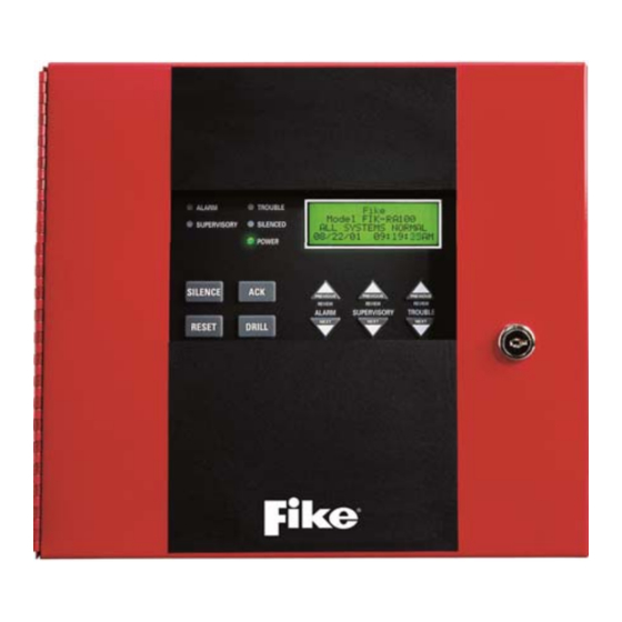
4.5 FIK-RA100 Remote Annunciator Installation The optional Model FIK-RA100 Remote Annunciator, is shown in Figure 4.9. The FIK-RA100 can be surface or flush mounted. Up to 16 FIK-RA100s can be added to the FCP-300/ECS System. Figure 4.9 Model FIK-RA100 Remote Annunciator, Front View The FIK-RA100 installation involves the following steps: Make sure power is off at the panel. - Page 31 Attach the annunciator and door assembly to back box as shown in Figure 4.12 using the supplied screws. Figure 4.12 Attaching Annunciator/Door Assembly to Backbox Surface Mounting The optional Model FIK-RA100TR Trim Ring Kit is available for use when surface mounting. Remove the desired knock out. See Figure 4.11. FCP-300/FCP-300ECS Manual — P/N LS10145-002FK-E:A 3/12/2021...
- Page 32 After the annunciator wiring to the panel has been completed (described in Section Figure 4.5), replace the electronic assembly in the back box. Place the bezel over the back box and tighten the set screws on the bezel. FCP-300/FCP-300ECS Manual — P/N LS10145-002FK-E:A 3/12/2021...
-
Page 33: 2: Connecting The Fik-Ra100 To The Panel
The optional Model FIK-RA1000 is a remote annunciator that uses a Fireman’s key or access code to reset or silence. Up to 16 annunciators in any combination can be added to the FCP-300/ECS System. Figure 4.16 Model FIK-RA1000 Remote Annunciator, Front View The FIK-RA1000 installation involves the following steps: Make sure power is off at the panel. -
Page 34: 1: Mounting The Fik-Ra1000
5/64 hex wrench to remove the set screws, located on the bottom of the annunciator bezel. (See Figure 4.18 for loca- tion of the set screws.) Figure 4.18 Annunciator Back Box and Bezel Details Flush Mounting This Section of the manual describes flush mounting. You can flush-mount with or without an electrical box. FCP-300/FCP-300ECS Manual — P/N LS10145-002FK-E:A 3/12/2021... -
Page 35: 2: Connecting The Fik-Ra1000 To The Panel
The FIK-RA2000 module must be added to the System through programming. JumpStart will add the module automatically (see Section 8.1.3). You can also add it manually (see Section 9.2.2). Select a name, if desired (See “Naming Modules” on page 121.). FCP-300/FCP-300ECS Manual — P/N LS10145-002FK-E:A 3/12/2021... -
Page 36: 1: Mounting The Fik-Ra2000
Remove knockout holes as needed for wires. See Figure 4.11 for backbox knockout locations. Wire Knockouts Wire Knockouts Wire Knockouts Figure 4.22 Back Box Knockout Locations Wire the annunciator board to the main control panel. As described in Section 4.7.2. FCP-300/FCP-300ECS Manual — P/N LS10145-002FK-E:A 3/12/2021... - Page 37 Place a level on top of the back box, with the back box level insert the rest of the mounting screws Key Shaped Mounting Hole Back Box Mounting Holes Figure 4.24 Back Box Surface Mount Holes Run wires to the control panel. FCP-300/FCP-300ECS Manual — P/N LS10145-002FK-E:A 3/12/2021...
-
Page 38: 2: Fik-Ra2000 Connection To The Panel
The FIK-6815 SLC expander offers the option to add additional addressable devices. The maximum number of SLC devices per panel is 300. The number of FIK-6815’s is limited by the maximum number of SBUS devices. NOTE: The FIK-6815 will support Fike, Silent Knight or SWIFT SLC devices. To install the FIK-6815, do the following. -
Page 39: 1: Fik-6815 Connection To The Panel
The printer must be a UL 864 listed printer. To install the FIK-5824, do the following: Make sure the power is off at the panel. Connect the FIK-5824 to the panel as shown in Figure 4.29. FCP-300/FCP-300ECS Manual — P/N LS10145-002FK-E:A 3/12/2021... -
Page 40: 1: Selecting Fik-5824 Options
If you use a Serial Printer, use the next screen to select the serial port options as required for your printer. Refer to your Printer Manual if you need more information. Option Choices Baud Rate: 75 - 19200 Data Bits: 5 - 8 Stop Bits: .5, 1, 2 Parity: None, Even, Odd Table 4.4TPrinter Output Options FCP-300/FCP-300ECS Manual — P/N LS10145-002FK-E:A 3/12/2021... -
Page 41: Fik-5880 Led I/O Module
• panel and the contact monitor wiring • pin connectors for connecting LEDs • DIP switch for selecting an SBUS ID number Dry Contact Inputs - Supervised/Power-Limited SBUS Address DIPs SBUS Connection Figure 4.31 FIK-5880 Board Layout FCP-300/FCP-300ECS Manual — P/N LS10145-002FK-E:A 3/12/2021... -
Page 42: 2: Fik-5880 Connection To Panel
NOTE: The circuit connected to the common “Open Collector Output” (the last pin on the P1) must be current-limited, so that no more than 100 mA of the current is allowed to flow into the Open Collector Transistor. FCP-300/FCP-300ECS Manual — P/N LS10145-002FK-E:A 3/12/2021... -
Page 43: 4: Dry Contact Wiring
FIK-5865-3 and FIK-5865-4 hardware. For the programming information, refer to Section 9. NOTE: This manual uses the FIK-5865 when it references aspects of the FIK-5865-3 and FIK-5865-4 that are common to both models. Figure 4.35 FIK-5865-3 and FIK-5865-4 Assembly (Front View) FCP-300/FCP-300ECS Manual — P/N LS10145-002FK-E:A 3/12/2021... -
Page 44: 1: Fik-5865 Connection To Panel
Mount the FIK-5865-4 to a standard 4-gang electrical box. Mount the FIK-5865-3 to a standard 3-gang electrical box. In Figure 4.37, the FIK-5865-4, attached to a 4-gang box, is used as an example. Figure 4.37 FIK-5865 Mounting Example FCP-300/FCP-300ECS Manual — P/N LS10145-002FK-E:A 3/12/2021... -
Page 45: Configuring Sbus Modules
Figure 4.39 shows all possible DIP switch positions and their correlation to a numerical ID. For example, to select the ID 2, place the DIP switch 2 in the UP position. Figure 4.39 Possible module addresses To edit, add, delete, and View Module List, Refer to Section 9.2. FCP-300/FCP-300ECS Manual — P/N LS10145-002FK-E:A 3/12/2021... -
Page 46: 2: Sbus Bandwidth Considerations
Four outputs are built-in to the FCP-300 FACP which can be programmed to be used as the NACs (Class A or Class B) or pro- grammed as the Aux power. This Section of the manual explains how to install the conventional notification appliances and describes how these terminals can be used for the auxiliary power. - Page 47 Wire the Class A notification appliances as shown in Figure 4.42. CAUTION: For proper System supervision, do not use the looped wire under the terminals marked + and – of the Flexput connectors. The Break wire runs to provide supervision of connections. FCP-300/FCP-300ECS Manual — P/N LS10145-002FK-E:A 3/12/2021...
-
Page 48: 2: Auxiliary Power Installation
30 seconds, then re-applied. Sounder Sync Power The Sounder Sync Power continuously outputs the System Sensor synchronization pattern and is intended for use with the B200S sounder bases. FCP-300/FCP-300ECS Manual — P/N LS10145-002FK-E:A 3/12/2021... -
Page 49: On-Board Relays (Conventional)
Program the control panel Relay 2 for alarm. Program the NAC circuit 2 for alarm. Program the NAC circuit 1 for supervisory non latching. NOTE: The NACs must be programmed for continuous and non-silencing. FCP-300/FCP-300ECS Manual — P/N LS10145-002FK-E:A 3/12/2021... -
Page 50: 2: City Box Connection Using The 5220 Module
3 and 4 on the 5220. Do not install an EOL resistor in the terminals of the NAC circuit used for this application. Connect earth ground wire to the 5220 chassis with mounting screw. FCP-300/FCP-300ECS Manual — P/N LS10145-002FK-E:A 3/12/2021... -
Page 51: Using The Addressable Relay Module For City Box Connection
4.17 Using the Addressable Relay Module for City Box Connection Wire the Relay module as shown in Figure 4.46. UL listed EOL must be Installed in City Box Enclosure Figure 4.46 Relay Module for City Box Connection FCP-300/FCP-300ECS Manual — P/N LS10145-002FK-E:A 3/12/2021... -
Page 52: 1: Nfpa 72 Polarity Reversal
When the 7644 is used for polarity reversal, it allows the alarm and the trouble events to be reported to a remote site. The Alarms will override the trouble conditions and it will not be possible to reset the remote indicator until the condition is cleared and the control panel is reset. FCP-300/FCP-300ECS Manual — P/N LS10145-002FK-E:A 3/12/2021... - Page 53 Program the NAC circuit as a notification circuit. See Section 9.5.4. Map the group to activate the constant on from the zone event. Program the output group characteristics as non-silenceable and reverse polarity. Figure 4.48 Polarity Reversal Connection Using the 7644-L8 FCP-300/FCP-300ECS Manual — P/N LS10145-002FK-E:A 3/12/2021...
-
Page 54: 2: Transmitter Activated By Dry Contacts
4.17.2 Transmitter Activated by Dry Contacts This Section describes the connection of a UL 864 Listed Remote Station Transmitter to the FCP-300 FACP dry contacts. The FACP contacts must be supervised by the Remote Station Transmitter module using the end-of-line resistors (ELRs) with a value determined by the Transmitter Manufacturer. -
Page 55: Section 5: Networking
System failure. 5.2 Network Wiring When you network a group of FCP-300/ECS you must use the FIK-NIC to link the panels together. See Figure 5.1 and Figure 5.2, for the Internal mounting or external mounting of the FIK-NIC options. -
Page 56: Fik-Nic Wiring Options
Figure 5.2 Internal FIK-NIC Wiring Option 5.3 FIK-NIC Wiring Options Networking a group of FCP-300/ECS requires the use of a network interface card with each panel. The FIK-NIC connects to other networked units using unshielded, twisted-pair wiring or fiber-optic cable. - Page 57 Accessory Mounting Kits The FIK-NIC can be mounted within the FCP-300/ECS cabinet or in an accessory cabinet. Accessory cabinets include a small cabinet with door, key, and mounting hardware. An accessory kit is available if you want to install the FIK-NIC outside of the FCP-300/ECS cabinet.
-
Page 58: 2: Fik-Nic Installation
Figure 5.10 for the FIK-NIC wiring examples. To mount the FIK-NIC remotely: Follow the steps above, except the 6-pin cable, that runs from the FIK-NIC to the FCP-300 and must be run in conduit. See Figure 5.1. Unshielded Twisted Pair Wiring between Multiple Panels Unshielded twisted pair wiring between multiple panels is shown in Figure 5.7. - Page 59 The Fiber-optic cable between multiple panels is shown in Figure 5.8. Class A is shown with a dotted line. Class A wiring Figure 5.8 Fiber-Optic Wiring Multi-Mode Example Class A wiring Figure 5.9 Fiber-Optic Wiring Single-Mode Example FCP-300/FCP-300ECS Manual — P/N LS10145-002FK-E:A 3/12/2021...
-
Page 60: Setting The Network Id For Each Panel
The Network ID for each panel is set using the DIP switch positions 1 through 5. See Figure 5.11 below for possible DIP switch settings. Figure 5.11 Network ID Settings FCP-300/FCP-300ECS Manual — P/N LS10145-002FK-E:A 3/12/2021... -
Page 61: Section 6: Network Management
When you use the PC Configuration Software to program the panels, the Network Panel ID will be locked from future editing. The only way to change it will be to restore defaults and use this Menu again. FCP-300/FCP-300ECS Manual — P/N LS10145-002FK-E:A 3/12/2021... -
Page 62: 4: Computer Access
SLC Single Device Locator SLC Multiple Device Locator I/O Point Control Event History Set Time & Date System Information Network Diagnostics Network Programming Panel Programming Send/Receive Firmware Update User Profile Selectable Panel Functions Table 6.1 FCP-300/FCP-300ECS Manual — P/N LS10145-002FK-E:A 3/12/2021... -
Page 63: 6: Communicator Options
Receiver Configuration The FCP-300/ECS Network can report events to as many as 68 receivers. See Appendix C for panel/receiver relationship num- bers. Each receiver can be assigned reporting credentials. When using a format that supports phone numbers, it can be up to forty digits long. - Page 64 Select 6 for Network Programming. Press 6 to enter the Communicator Options Menu. Select 4 for the Communicator Reporting Table. Press * to add rows, Press ENTER to edit data. Figure 6.1 Communicator Reporting FCP-300/FCP-300ECS Manual — P/N LS10145-002FK-E:A 3/12/2021...
-
Page 65: Voice Options
The Control Lockout countdown timer is set to the programmed value when an LOC gains the Fike Series, ECS Control. The timer starts over upon any key press at the Fike Series, ECS Control LOC. While the Control Lockout Timer is active, an LOC of equal priority must request the Fike Series, ECS control. -
Page 66: Sync Network Options
Select Source Last Modified Chk sum 01 = Panel 1 04/12/13 12:20 0F8B 02 = Panel 2 04/15/13 09:45 0F8A 03 = Panel 3 04/15/13 09:46 0F8A FCP-300/FCP-300ECS Manual — P/N LS10145-002FK-E:A 3/12/2021... -
Page 67: Network Management Quick Reference
0= unused See Section 6.2.6 Assignments Communicator Enable pi SIA Modifier Options Communicator “Communicator SIA Options Miscellaneous Include Panel ID in SIA Reporting Miscellaneous” on page 63. Table 6.5 Network Management Quick Reference Chart FCP-300/FCP-300ECS Manual — P/N LS10145-002FK-E:A 3/12/2021... - Page 68 System Alert 1-5 Trouble Fire Interlock Release Fire Interlock Alert Emergency Supervisory Choose Site See Section 6.3.2 CO Alarm CO Supervisory Sync Network See Section 6.4 Options Table 6.5 Network Management Quick Reference Chart (Continued) FCP-300/FCP-300ECS Manual — P/N LS10145-002FK-E:A 3/12/2021...
-
Page 69: Section 7: Fike And Swift Slc Device Installation
7.2 SWIFT Wireless SLC Devices The FIK-W-WGI Wireless Gateway acts as a bridge between a group of wireless fire devices and an SLC loop on the FCP-300. It is powered by the SLC loop or it is powered by a regulated, external 24VDC UL-listed power supply. The available wireless devices include a photo detector, a heat detector, a fixed-temperature heat detector, a rate-of-rise detector, an ACCLIMATE detector, a pull sta- tion, a monitor module, and a relay module. -
Page 70: 1: Wire Sizing For Fik-6815
When you use the T-taps, the total length of all taps and the main bus must not exceed 40,000 feet. This requirement must be met in addition to the maximum distance requirements for the various wire gauges. FCP-300/FCP-300ECS Manual — P/N LS10145-002FK-E:A 3/12/2021... -
Page 71: 3: Wiring Fik-6815 In Style 6 & 7 (Class A) Configuration
NOTE 2: Style 7 requires an isolator module as the first device on the in and the out loop. NOTE 3: No t-taps allowed on class A SLC loops. Figure 7.3 Class A SLC Configuration FCP-300/FCP-300ECS Manual — P/N LS10145-002FK-E:A 3/12/2021... -
Page 72: Addressing The Fike Slc Devices
3- for Seq. Programming. Use to program more than one detector in sequential order. If you are changing addresses, write the programmed address on the back of the device. To exit press left arrow until fully exited. FCP-300/FCP-300ECS Manual — P/N LS10145-002FK-E:A 3/12/2021... -
Page 73: 1: Slc Devices With Dip Switches
300/ECS. It is powered by the SLC loops or by a regulated, external 24 VDC UL listed power supply. For updated details about wireless devices, system setup, and operation, see the SWIFT Smart Wireless Integrated Fire Technology Instruction Manual P/N LS10036-001FK-E. FCP-300/FCP-300ECS Manual — P/N LS10145-002FK-E:A 3/12/2021... -
Page 74: Section 8: Programming Overview
A series of messages display for the next several seconds. The JumpStart scans the SLC loops for devices. This process can take several minutes, depending on the number of devices attached. When the message “Configuring System Done” displays, press any key to continue. Select one of the following options from the Menu that displays. FCP-300/FCP-300ECS Manual — P/N LS10145-002FK-E:A 3/12/2021... -
Page 75: Mapping Overview
The Input Points are assigned to the Input Zones. Any input point can be assigned to any input zone. (Input points can be assigned to one zone only. An input point can be designated as “Unused,” which means it has not been assigned to a zone). FCP-300/FCP-300ECS Manual — P/N LS10145-002FK-E:A 3/12/2021... - Page 76 Programming Overview Mapping Overview Figure 8.2 Input Point Assignment Example FCP-300/FCP-300ECS Manual — P/N LS10145-002FK-E:A 3/12/2021...
-
Page 77: 2: Output Circuit Mapping
Zone Aux 2 Alarm Interlock Alert Fire Interlock Release Pre-Alarm Fire Supervisory Status Point CO Alarm CO Supervisory LOC ECS 1-8 Alarm General ECS Alarm Emergency General ECS Supervisory Point ECS 1-8 Alarm Table 8.2 Event Types FCP-300/FCP-300ECS Manual — P/N LS10145-002FK-E:A 3/12/2021... - Page 78 Printer Trouble System Mic Active Aux Power Trouble Background Music System Switch Trouble Output Group Trouble Table 8.2 Event Types (Continued) Figure 8.4 Example of Zone Events Mapped to the Output Groups and Patterns FCP-300/FCP-300ECS Manual — P/N LS10145-002FK-E:A 3/12/2021...
- Page 79 Programming Overview Mapping Overview Figure 8.5 Example of Zone Events Mapped to the Output Groups and Patterns FCP-300/FCP-300ECS Manual — P/N LS10145-002FK-E:A 3/12/2021...
- Page 80 Programming Overview Mapping Overview Figure 8.6 Example of Events Mapped to the Output Groups and Patterns within a Networked Site FCP-300/FCP-300ECS Manual — P/N LS10145-002FK-E:A 3/12/2021...
-
Page 81: 4: Mapping Led Points
The LED points are available when the Models FIK-5865-3/4 and/or FIK-5880 are used with the System). Figure 8.7 Example of LED Points Mapped to Output Groups (applies to Models FIK-5865-3/4 and FIK-5880) FCP-300/FCP-300ECS Manual — P/N LS10145-002FK-E:A 3/12/2021... -
Page 82: 5: Mapping Led Points For A Networked System
HFSS is needed for Mapping. When you use the HFSS tool, you can set up the programming options for the panel, save the options in a file, then download the file to the panel. You can directly connect to the control panel using the onboard USB. The updates are available at Fike website, www.fike.com. 8.4 Programming Using an Annunciator You can program the control panel from a System annunciator, using either the control panel’s on-board annunciator or an... -
Page 83: 2: Moving Through The Menus
FIK-INT50W-Voice Amplifier FIK-NVCM -Network Voice Control Module FIK-RVM- Remote Voice Module FIK-NIC Network Interface Card Delete Module Select Module Section 9.2.3 View Module List Select Module Section 9.2.4 Table 8.4 Programming Quick Reference Chart FCP-300/FCP-300ECS Manual — P/N LS10145-002FK-E:A 3/12/2021... - Page 84 00-23 (See Appendix C) Override Cadence View Group Points Select Group Section 9.4.2 Edit OPG Template Select template Modify name and which OPGs are in template Section 9.4.3 Table 8.4 Programming Quick Reference Chart (Continued) FCP-300/FCP-300ECS Manual — P/N LS10145-002FK-E:A 3/12/2021...
- Page 85 (cont.) Sensor External FIK-6815 Accessory SDR BAS RLY BAS PHOTO I-SdrBa (Intelligent Sounder 2,3,4,5 Base) DETECTOR 2,3,4,5,6 Accessory SDR BAS RLY BAS I-SdrBa (Intelligent Sounder 2,3,4,5 Base) Table 8.4 Programming Quick Reference Chart (Continued) FCP-300/FCP-300ECS Manual — P/N LS10145-002FK-E:A 3/12/2021...
- Page 86 2, 3, 4, 5 HEAT-HT I-SdrBa (Intelligent Sounder Base) Accessory SDR BAS PHOTO- RLY BAS 2,3,4,5 HEAT I-SdrBa (Intelligent Sounder Base) 2,3,4,5 BEAM LATCH Same function 1,2,3,4,5,6 as DETECTOR NON-LATCH Table 8.4 Programming Quick Reference Chart (Continued) FCP-300/FCP-300ECS Manual — P/N LS10145-002FK-E:A 3/12/2021...
- Page 87 FIK Devices on Select 3, 4,5,8 2,3,5 Point Photo-Heat Internal and Enter Pt Sensor 2,3,4,5,8 (cont.) Heat External FIK-6815 (cont.) W-SUP DET Same as W- 2,3,4,5,8 Detector Table 8.4 Programming Quick Reference Chart (Continued) FCP-300/FCP-300ECS Manual — P/N LS10145-002FK-E:A 3/12/2021...
- Page 88 ZONE AUX1, ZONE AUX2, System MANUAL AUX1, System AUX2., ECS INPUT, B SWITCH RELEASE ECS TAMPER, and ECS INTER-LOCK SUPERVISORY. If ECS INPUT is selected choose ECS INPUT associated EVENT Table 8.4 Programming Quick Reference Chart (Continued) FCP-300/FCP-300ECS Manual — P/N LS10145-002FK-E:A 3/12/2021...
- Page 89 ECS INPUT FIK-RVM/ Point Enter Pt /Select Function FIK-ECS/ SWITCH ECS TAMPER Section 9.5.7 (cont.) FIK-NVCM ECS SUPERVISORY VOICE AUX STATUS 1-2 BACKGROUND MUSIC VOICE AUX ECS 1-4 Table 8.4 Programming Quick Reference Chart (Continued) FCP-300/FCP-300ECS Manual — P/N LS10145-002FK-E:A 3/12/2021...
- Page 90 Time Options Section 9.6.4 Internal AM/PM Clock Display Format *AM/PM 4 hours Auto-resound *24 hours 24 hours SYNC Strobes when Silenced Miscellaneous Section 9.6.5 Options Auto Display Events Table 8.4 Programming Quick Reference Chart (Continued) FCP-300/FCP-300ECS Manual — P/N LS10145-002FK-E:A 3/12/2021...
- Page 91 Available on the FIK-6815 External. Available on the FIK-6815 Internal. Available with the SLC Family as Fike. Requires the Fike Series, ECS Module programmed into the panel. Available with SLC Family as SK. Available with SLC Family as SD. Requires Fike Series, Module programmed into the panel.
-
Page 92: Section 9: Programming
FIK-5880 LED I/O module • FIK-INT50W or FIK-DUAL50W watt audio amplifier • FIK-NIC network interface card • FIK-5865 LED annunciator • • FIK-6815 SLC Loop Expander for Fike devices • FIK-NVCM network voice control module • FIK-5824 serial/parallel printer interface module •... -
Page 93: 2: Adding A Module
Through the Zone option in the Program Menu, you can edit and view zone points. Selections made here affect all detectors and switches in the zone. Up to 250 zones can be used in the System. FCP-300/FCP-300ECS Manual — P/N LS10145-002FK-E:A 3/12/2021... -
Page 94: 1: Edit Zone
Figure 9.2 Editing Zone Properties NOTE: You can only see the smoke sensitivity on the FCP-300/ECS if the Daytime/Nighttime Sensitivity is set to off under the System Options. (See Section 9.6.2). Otherwise, if the Daytime/Nighttime Sensitivity is on, this will bring up a Smoke Sens Day and Night, 2 separate widgets with sensitivity as being either low, med, high for each device. - Page 95 Then, press ENTER. NOTE: If the SLC protocol is changed from Fike to SK to SD and a zone's sensitivity is higher than the SD limit, the zone sensitivity will be set to the maximum value of 150 for the SD family.
-
Page 96: 2: View Zone Points
Programming Group NOTE: If the SLC protocol is changed to Fike-IDP, the FIK Series and the cadence is no longer valid for Fike. The Zone Cadence will be set to constant ON. 9.3.2 View Zone Points To view the points in a zone, follow these steps: Enter the Installer Code. -
Page 97: 2: View Group Points
You can use words to display a descriptive name for a group. NOTE: See Appendix B for editing names. Press the right arrow to the OPG and select YES or NO to select which output groups to include in the template. FCP-300/FCP-300ECS Manual — P/N LS10145-002FK-E:A 3/12/2021... -
Page 98: Point
Wireless photoelectric detectors. Non Latching ACCLIMATE (FIK) Wireless acclimate photoelectric detector. PHOTO-HEAT (SK) Wireless heat detector. HEAT W-SUP DET Same as W- Latching Wireless photoelectric detectors. Detector Non Latching Table 9.5 Programming Options for FIK-6815 Modules FCP-300/FCP-300ECS Manual — P/N LS10145-002FK-E:A 3/12/2021... - Page 99 Performs identically to a supervisory switch, but will be indicated as a tamper switch on the LCD annunciator. Non Latching MANUAL RELEASE Manual release switch INTERLOCK Interlock release switch input. STATUS POINT Table 9.5 Programming Options for FIK-6815 Modules (Continued) FCP-300/FCP-300ECS Manual — P/N LS10145-002FK-E:A 3/12/2021...
-
Page 100: 2: Point Programming For The Internal Or The External Power Module (Fik-Rps1000)
11. Press ENTER to edit point name. See “Editing Text Using the Built-In Programmer” on page 206. Or, Press right arrow key to skip point name edit. 12. Repeat Steps 1 through 11 for all circuits. FCP-300/FCP-300ECS Manual — P/N LS10145-002FK-E:A 3/12/2021... -
Page 101: 3: Point Programming For Fik-5880 Or 5865 Modules
9.5.3 Point Programming For FIK-5880 or 5865 Modules To program the Model FIK-5880 or 5865 module points, do the following. Enter the Installer Code. Select 7 for Program Menu. Press 4 to enter Point Menu. FCP-300/FCP-300ECS Manual — P/N LS10145-002FK-E:A 3/12/2021... -
Page 102: 4: Point Programming For Fik-5496
9.5.5 Point Programming for FIK-AMP To program module points, do the following. Enter the Installer Code. The panel will automatically access the Main Menu. Select 7 for Panel Programming. Press 4 to enter Point Menu. FCP-300/FCP-300ECS Manual — P/N LS10145-002FK-E:A 3/12/2021... -
Page 103: 6: Point Programming For Fik-Nvcm And Fik-Rvm Modules
10. Repeat Steps 1 through 9 for all points. Function Selections for Choices Type Selections Comments each Type FIK-5880 (output) UNUSED NOTIF NOTIF OUTPUT (outputs pt 1-40) CONTROL CIRCUIT Table 9.7 Point Programming Options for FIK-NVCM and FIK-RVM FCP-300/FCP-300ECS Manual — P/N LS10145-002FK-E:A 3/12/2021... - Page 104 CONTROL CIRCUIT AUX_PWR CONSTANT AUX RESET AUX DOOR AUX SYNC Can not be supervised FIK-5865 UNUSED NOTIF NOTIF OUTPUT CONTROL CIRCUIT FIK-AMP UNUSED NOTIF Table 9.7 Point Programming Options for FIK-NVCM and FIK-RVM (Continued) FCP-300/FCP-300ECS Manual — P/N LS10145-002FK-E:A 3/12/2021...
-
Page 105: System Options
To access the phone lines screen, do the following. Enter the Installer Code. Select 7 for the Program Menu. From the Program Menu, select 5 for the System Options. Select 1 for the Communication Opts. Select 2 for the Phone Lines Menu. FCP-300/FCP-300ECS Manual — P/N LS10145-002FK-E:A 3/12/2021... - Page 106 European format. Uses the 66 msec / 34 msec make/break ratio. Dial Tone Detection Disabled 11. Select Y (do disable) or N (don’t disable) by pressing the up or down arrow key, then press ENTER. FCP-300/FCP-300ECS Manual — P/N LS10145-002FK-E:A 3/12/2021...
- Page 107 Figure 9.11 AlarmNet Timers Phone Line Gains Enter the Installer Code. The panel will automatically access the Main Menu. Select 7 for Panel Programming. Select 5 for System Options. FCP-300/FCP-300ECS Manual — P/N LS10145-002FK-E:A 3/12/2021...
-
Page 108: 2: Daytime/Nighttime Sensitivity
Select the holiday schedules you want to edit (1- holidays 1 - 9, 2- holidays 10 - 18). Enter the month of the holiday, then press ENTER. Enter the day of the month for the holiday, then press ENTER. Repeat steps 6 for any remaining holidays you want to program. FCP-300/FCP-300ECS Manual — P/N LS10145-002FK-E:A 3/12/2021... -
Page 109: 4: Time Options
Through this Programming option, you can turn on or turn off the Strobe Synchronization during the silence and the display status at idle (auto display event). To edit Miscellaneous Options, do the following. Enter the Installer Code. Select 7 for the Program Menu. FCP-300/FCP-300ECS Manual — P/N LS10145-002FK-E:A 3/12/2021... -
Page 110: 6: Daylight Saving Options
When word or sentence is complete, press ENTER to save the custom banner. 9.6.8 SLC Family The FCP-300/ECS supports the FIK Series SLC devices. You must configure the FCP-300 to accept the Fike-IDP protocol you are installing. FCP-300/FCP-300ECS Manual — P/N LS10145-002FK-E:A 3/12/2021... -
Page 111: Jumpstart® Autoprogramming
This option allows you to select whether the dual channel is enabled in the System. For the dual channel capabilities, the Sys- tem must only contain the dual channel voice hardware. Press the up or down arrow key to select YES or NO to enable the System as dual channel. Then, press ENTER. FCP-300/FCP-300ECS Manual — P/N LS10145-002FK-E:A 3/12/2021... -
Page 112: Section 10: System Operation
The Banner is the message that displays on the control panel when the System is in the normal mode (no alarm or trouble condition exists and menus are not in use). You can create a customized message that will display instead of the internal (default) message. For information on customizing the banner, see Section 9.6.7, FCP-300/FCP-300ECS Manual — P/N LS10145-002FK-E:A 3/12/2021... -
Page 113: 3: Single Key Acknowledge
Use the up or down arrow key to select the options in the fields. When the date and time are correct, press ENTER. 10.4.2 Disable / Enable a Point Select 2 for the Point Functions. Select 1 for the Disable/Enable Point. FCP-300/FCP-300ECS Manual — P/N LS10145-002FK-E:A 3/12/2021... -
Page 114: 3: View Event History
This test takes approximately 15 seconds to complete. You can press any key to manually end while the Test is still in progress. When the Test ends, you will be returned to the <Test Menu>. FCP-300/FCP-300ECS Manual — P/N LS10145-002FK-E:A 3/12/2021... -
Page 115: 6: Conduct A Walk Test
NOTE 1: The Multi-Site displays do not allow for resetting the multiple sites. To reset a site, enter a multi-site access password, select a site, and then press RESET. NOTE 2: For Fike Series, ECS Systems, pressing reset at an LOC will prompt the user for which System they want to reset. See Section 10.5.1 Reset Communicator This option allows the user to Reset the Communicator. -
Page 116: 11: Check Detector Sensitivity Through Point Status
From the Main Menu, press 8 to access the System Information Menu. About Panel Press 1 to access the About Panel to view the Panel Model, Serial Number and System Version number and date. FCP-300/FCP-300ECS Manual — P/N LS10145-002FK-E:A 3/12/2021... -
Page 117: Event Priority
There are times when you would not want to allow System Override for an output group. For example: fire is programmed to an elevator relay to bring the elevator to the bottom floor for fire only. If fire and Fike Series, ECS are active with ECS being the higher priority event, you still need the elevator to move to the bottom floor and only audible and visual notification appli- ances must be overridden. -
Page 118: 4: Priority Rules
The Emergency LOC Alarm must always be higher than the Emergency 1-8 Point Alarm and Emergency Voice Aux 1-4 Alarm. The Fike Series, ECS events do not need to be set in order by the ECS number. 10.5.5 Other Priority Considerations There are other considerations to take into account when the same event is acting on the same output group (an event being mapped to an output group.) These are prioritized in order of appearance:... - Page 119 A smoke detector goes into alarm or Alarm a pull station is activated. FIRE: ALARM SUPERVISORY TROUBLE ALARM SUPERVISORY EMERGENCY: ALARM SUPERVISORY SYSTEM: TROUBLE Table 10.4 Operations Mode Behavior FCP-300/FCP-300ECS Manual — P/N LS10145-002FK-E:A 3/12/2021...
- Page 120 Menus are not available during the reset process. button is pressed “RESET IN PROGRESS”. If the reset process followed by a completes normally, the date and time normal valid code, if mode screen displays. necessary. Table 10.4 Operations Mode Behavior (Continued) FCP-300/FCP-300ECS Manual — P/N LS10145-002FK-E:A 3/12/2021...
-
Page 121: 1: Multi-Site Annunciator And Multi-Site User Access
NOTE 1: A multi-site display is created in Module programming in the edit properties menu for an annunciator. See section 9.2.1. NOTE 2: An annunciator cannot be programmed as a multi-site display when it is associated with an FIK-NVCM or FIK-RVM in a Fike Series, ECS System. -
Page 122: 1: Single Interlock Zone Releasing
If any single addressable detector is activated, the “Interlock Release Alert” output will activate. This alerts the user that the initial stages required for a release condition are present. (Also refer to Table 10.6). Conditions required for a Detector Alarm and Interlock Release Alarm Output FCP-300/FCP-300ECS Manual — P/N LS10145-002FK-E:A 3/12/2021... -
Page 123: 2: Double Interlock Zone Releasing
Output Results Addressable Detector Addressable Detector Manual Release Station Interlock/ Pressure Switch Interlock Release Normal Interlock Release Alert and Detector Alarm Interlock Release Alarm and Detector Alarm Alert Table 10.7 Double Interlock Zone Operation FCP-300/FCP-300ECS Manual — P/N LS10145-002FK-E:A 3/12/2021... -
Page 124: Smoke Alarm Verification
10.9 Function Keys The function keys on the FCP-300/ECS have multiple features. Their macro key functionality can simplify the disabling, acti- vating, or inhibiting points or groups respectively. They can also be used as a status type activation event and for activating Map Inhibit. -
Page 125: Section 11: Emergency Communication System Operation
The Fike Series, ECS control panels and accessories provide features to meet the requirements for Mass Notification Systems as described in NFPA 72 and is compliant with the UL 2572 standard. The Fike Series, ECS (Emergency Communication System) is inte- grated with the fire alarm and voice evacuation functions of the control panel. -
Page 126: 2: Gaining Ecs Control
ECS Alarm programmed points that are currently in alarm in the System are changed to an active state. The display status screen reflects this when viewing the System for status. Any outputs that were activated by the ECS Alarm programmed points FCP-300/FCP-300ECS Manual — P/N LS10145-002FK-E:A 3/12/2021... -
Page 127: 4: Microphone Mode
Figure 11.2) will display in which the user can: request control from the LOC with ECS Control, enter an access code with the ECS Super User profile option to override the other LOC, or wait for the lockout timer to expire (if applicable). Figure 11.2 Request ECS Control with Lockout Timer Active FCP-300/FCP-300ECS Manual — P/N LS10145-002FK-E:A 3/12/2021... -
Page 128: 8: Exit Ecs Control Menu
Active state, and the detailed description of the point will show the point as Active. After an ECS Reset, any ECS points that are still active will again be put into Alarm. FCP-300/FCP-300ECS Manual — P/N LS10145-002FK-E:A 3/12/2021... -
Page 129: 2: Fik-Nvcm & Fik-Rvm Points
NOTE: If you Add a Module that has not been physically connected, the panel will go into trouble after it re-initializes (when you exit the Program Menu). When the new module is attached, the trouble will correct itself automatically the next time you power up the System. FCP-300/FCP-300ECS Manual — P/N LS10145-002FK-E:A 3/12/2021... -
Page 130: 2: Editing An Loc
This will trigger the ECS System and enable mapping for 'Mic Triggered ECS Alarm' and 'General ECS Alarm'. Paging If there are no active Emergency or Fire System Events, you can use the microphone at an LOC for paging by following these steps: Push the PTT (Push-To-Talk) button on the microphone. FCP-300/FCP-300ECS Manual — P/N LS10145-002FK-E:A 3/12/2021... -
Page 131: Recording Custom Messages
Select Key LED will be off. While recording a particular message, the red Select Key will turn on until the recording is completed. The Select Key 1-15 will be used to playback a recorded message or to select a message slot to record to or erase. FCP-300/FCP-300ECS Manual — P/N LS10145-002FK-E:A 3/12/2021... -
Page 132: 1: Recording Messages 1-15 Using Aux Audio Input
Section 11.8.3). When the message has been erased Select Key 2’s green LED will turn off. To record a message, press ECS Message Key 1, then press Select Key 2 (this will use message slot 2 for the recording). Select Key 2's red LED will begin flashing. FCP-300/FCP-300ECS Manual — P/N LS10145-002FK-E:A 3/12/2021... -
Page 133: 2: Recording Messages 1-15 Using The Microphone
Press the push-to-talk button on the microphone and speak your message. Release the PTT button to save your message. Select Key 5's red LED stays on until processing is completed. Select Key 5's green LED comes on after the recording is completed. FCP-300/FCP-300ECS Manual — P/N LS10145-002FK-E:A 3/12/2021... -
Page 134: 3: Erasing User Message
PC hard drive) to the various message locations of the FIK-Series FIK-NVCM. Messages can be uploaded from the FIK-NVCM, stored, and used again in similar installations. To read/write .SKE formatted messages to and from the main panel, follow these steps: Make sure that panel is in Normal mode. FCP-300/FCP-300ECS Manual — P/N LS10145-002FK-E:A 3/12/2021... -
Page 135: Network Paging
The panel that is the Network Paging source will continue to play any alarms that are active as long as the alarm circuits aren't outputting the microphone page FCP-300/FCP-300ECS Manual — P/N LS10145-002FK-E:A 3/12/2021... -
Page 136: Section 12: Reporting
ORNN000000 Fire System Overridden FSNN000000 Fire System Override Restore FRNN000000 Ground fault condition trouble Exp. ID YPNNXX0000 Exp. ID Ground fault condition trouble Exp. ID YQNNXX0000 Exp. ID restore Table 12.2 Report Formats Table FCP-300/FCP-300ECS Manual — P/N LS10145-002FK-E:A 3/12/2021... - Page 137 Unable to report to account trouble Receiver # RTNN00RRRR Receiver # Unable to report to account trouble restore Receiver # YKNN00RRRR Receiver # User access code changed JVNN000000 Table 12.2 Report Formats Table (Continued) FCP-300/FCP-300ECS Manual — P/N LS10145-002FK-E:A 3/12/2021...
- Page 138 Status Point Types Trouble UTNN000000 Status Point Types Trouble Restore UJNN000000 Supervisory Detector Alarm Zone # FSNN000ZZZ Zone # Supervisory Detector Alarm Restore Zone # FRNN000ZZZ Zone # Table 12.2 Report Formats Table (Continued) FCP-300/FCP-300ECS Manual — P/N LS10145-002FK-E:A 3/12/2021...
- Page 139 Exp. ID UJ Point # UJNNXXPPPP Exp. ID Point # stored Background Music Switch is Disabled pi Exp. ID UB Point # UBNNXXPPPP Exp. ID Point # Table 12.2 Report Formats Table (Continued) FCP-300/FCP-300ECS Manual — P/N LS10145-002FK-E:A 3/12/2021...
- Page 140 Exp. ID UJ Point # UJNNXXPPPP Exp. ID Point # trouble restore Interlock switch alarm (Water Release pi Exp. ID FA Point # FANNXXPPPP Exp. ID Point # Zone) Table 12.2 Report Formats Table (Continued) FCP-300/FCP-300ECS Manual — P/N LS10145-002FK-E:A 3/12/2021...
- Page 141 Supervisory/Tamper Alarm Restore pi Exp. ID FR Point # FRNNXXPPPP Exp. ID Point # Supervisory/Tamper point disabled pi Exp. ID FB Point # FBNNXXPPPP Exp. ID Point # Table 12.2 Report Formats Table (Continued) FCP-300/FCP-300ECS Manual — P/N LS10145-002FK-E:A 3/12/2021...
- Page 142 Zone-based AUX1 switch alarm restore pi Exp. ID UH Point # UHNNXXPPPP Exp. ID Point # Zone-based AUX1 switch disabled pi Exp. ID UB Point # UBNNXXPPPP Exp. ID Point # Table 12.2 Report Formats Table (Continued) FCP-300/FCP-300ECS Manual — P/N LS10145-002FK-E:A 3/12/2021...
-
Page 143: Sia - Fcp-300/Ecs Panels Pi Modifier Contact Reporting
Point # UJNNXXPPPP Exp. ID Point # Table 12.2 Report Formats Table (Continued) 12.2 SIA - FCP-300/ECS Panels PI Modifier Contact Reporting: Events are sent to the Central Station as a variable length string: The event format is: EEZZZZ Where: Event code (2 characters) ZZZZ Event parameter (up to four digits –... -
Page 144: Sia - Panel Communicator
EE-PP-MM-ZZZZ FT22970200 Fire Trouble Zone EE-PP-MM-ZZZZ FT22970001 MM = 00 Fire Trouble-Nac Point Nac Circuit 7 EE-PP-MM-ZZZZ FT22980007ZZZZ=Pt. # Fire Trouble-Nac Zone Nac Circuit 7 EE-PP-MM-ZZZZ FT22980007 ZZZZ=OPG # Table 12.4 SIA Reporting Examples FCP-300/FCP-300ECS Manual — P/N LS10145-002FK-E:A 3/12/2021... -
Page 145: Section 13: Testing And Troubleshooting
This Section of the Manual offers suggestions for troubleshooting hardware problems. Please read this section if you encounter a problem when installing the control panel. If these suggestions do not solve your problem or if you encounter a problem that is not listed here, for assistance contact Fike Technical Support at 800-979-FIKE (3453) (www.fike.com). Common Problems:... -
Page 146: Event History
If you select ENTER, the System will cease the normal operation, leaving the premise unprotected. Select the SLC loop. Enter up to 8 SLC addresses for the devices you want to locate. The LEDs on the selected devices will start flashing. FCP-300/FCP-300ECS Manual — P/N LS10145-002FK-E:A 3/12/2021... -
Page 147: 3: I/O Point Control
NAC 2 – NAC 1 SBUS OUT SBUS1 OUT EXT. COMM SLC Terminals SLC OUT SLC IN Note: Any wire to wire fault impedance is 0 ohms. Table 13.2 Earth Fault Resistance Values by Terminal FCP-300/FCP-300ECS Manual — P/N LS10145-002FK-E:A 3/12/2021... -
Page 148: Section 14: Installation Records
On-board 75 On-board On-board 76 On-board On-board 77 On-board On-board 78 On-board On-board 79 On-board On-board 80 On-board On-board 81 On-board On-board 82 On-board On-board 83 On-board Table 14.1 : Installation Record of Onboard Devices FCP-300/FCP-300ECS Manual — P/N LS10145-002FK-E:A 3/12/2021... - Page 149 Use the table below to record devices installed on additional SLC loops. Make a copy of this page if additional pages are needed. Module Addr Zone / Group Description Module Addr Zone/ Group Description Table 14.2 : Installation Record of Devices Installed on SLC FCP-300/FCP-300ECS Manual — P/N LS10145-002FK-E:A 3/12/2021...
-
Page 150: Conventional Output Point Record
Table 14.2 : Installation Record of Devices Installed on SLC (Continued) 14.2 Conventional Output Point Record This chart can be used to keep track of how conventional output points (circuits) have been configured. Point/Circuit Group Description Table 14.3 Conventional Output Point Record FCP-300/FCP-300ECS Manual — P/N LS10145-002FK-E:A 3/12/2021... -
Page 151: Appendix A: Compatible Devices
S2415-FC Strobe S241575-FC Strobe S2430-FC Strobe 130-3117C Mini Horn 130-3147C Mini Horn BLV-6 Vibrating Bell BLV-10 Vibrating Bell BLVCH Vibrating Chime H12/24-FC Horn H12/24W-FC Horn H12/24K-FC Horn HC12/24-FC Horn Table A.1 Compatible Notification Appliances FCP-300/FCP-300ECS Manual — P/N LS10145-002FK-E:A 3/12/2021... - Page 152 Horn/Strobe P24110-FC Horn/Strobe P24110W-FC Horn/Strobe P24110K-FC Horn/Strobe S2430W-FC Strobe S2430K-FC Strobe S2475-FC Strobe S2475W-FC Strobe S2475K-FC Strobe S24110-FC Strobe S24110W-FC Strobe S24110K-FC Strobe Horn Federal Signal VALS Horn/Strobe Table A.1 Compatible Notification Appliances (Continued) FCP-300/FCP-300ECS Manual — P/N LS10145-002FK-E:A 3/12/2021...
- Page 153 Multi Candella Strobe GESR-24 Multi Candella Strobe GEH-24 Horn ST24-30 Strobe ST24-60 Strobe ST24-75 Strobe ST24-110 Strobe Gentex (cont.) ST24-1575 Strobe WGEC24-75W Weatherproof Horn/Strobe WGES24-75W Weatherproof Strobe WGMS-24-X Horn/Strobe Table A.1 Compatible Notification Appliances (Continued) FCP-300/FCP-300ECS Manual — P/N LS10145-002FK-E:A 3/12/2021...
- Page 154 2-Wire Horn/Strobe High Candela P2RK 2-Wire Horn/Strobe PC2RK 2-Wire Horn/Strobe P2RHK 2-Wire Horn/Strobe High Candela PC2RHK 2-Wire Horn/Strobe High Candela 4-Wire Horn/Strobe PC4R 4-Wire Horn/Strobe P4RH 4-Wire Horn/Strobe High Candela Table A.1 Compatible Notification Appliances (Continued) FCP-300/FCP-300ECS Manual — P/N LS10145-002FK-E:A 3/12/2021...
- Page 155 Strobe WHT Ceil CLR Lens 4x4 SGRL Strobe Red Wall 2x4 SGWL Strobe White Wall 2x4 P2RH-LF 2-Wire Low Frequency Sounder Strobe P2WH-LF 2-Wire Low Frequency Sounder Strobe HR-LF Low Frequency Sounder Table A.1 Compatible Notification Appliances (Continued) FCP-300/FCP-300ECS Manual — P/N LS10145-002FK-E:A 3/12/2021...
- Page 156 AS-24MCW Horn/Strobe AS-24MCWH Horn/Strobe ASWP-2475W Horn/Strobe Weatherproof ASWP-2475C Horn/Strobe Weatherproof ASWP-24MCWH Horn/Strobe ASWP-24MCCH Horn/Strobe CH-70 Chime CH-90 Chime CH70-241575W Chime/Strobe CH70-24MCW Chime/Strobe CH70-24MCWH Chime/Strobe CH90-24MCC Chime/Strobe CH90-24MCCH Chime/Strobe Table A.1 Compatible Notification Appliances (Continued) FCP-300/FCP-300ECS Manual — P/N LS10145-002FK-E:A 3/12/2021...
- Page 157 ZNS-24MCC Horn/Strobe ZNS-24MCCH Horn/Strobe RSS-121575W Strobe RSS-241575W Strobe RSS-24MCC Strobe RSS-24MCCR Strobe RSS-24MCCH Strobe RSS-24MCCHR Strobe RSS-24MCW Strobe RSS-24MCWH Strobe RSSP-121575W Strobe RSSP-241575W Strobe RSSR-2415W Strobe RSSR-2415C Strobe Table A.1 Compatible Notification Appliances (Continued) FCP-300/FCP-300ECS Manual — P/N LS10145-002FK-E:A 3/12/2021...
-
Page 158: A.1.1: Two Wire Detectors
NOTE 2: Do not mix different models of detectors on any zone; false alarms could occur. NOTE 3: Control unit Smoke Reset Time must be programmed for a number greater than or equal to the maximum reset time of the smoke detector. FCP-300/FCP-300ECS Manual — P/N LS10145-002FK-E:A 3/12/2021... -
Page 159: A.2: Four-Wire Smoke Detectors/Devices (Ul Listed)
System Sensor DH400ACDCP Photoelectric Duct System Sensor 1112/24/D Ionization 0.05 System Sensor 1424 Ionization 0.10 System Sensor 1451 (w/B402B Base) Ionization 0.10 System Sensor 2112/24ATR Photoelectric 0.50 60/70 Table A.2 Compatible Four-Wire Smoke Detectors FCP-300/FCP-300ECS Manual — P/N LS10145-002FK-E:A 3/12/2021... - Page 160 Loop Test/Maintenance Mod. System Sensor RRS-MOD Reversing Relay/Sync Module System Sensor 6424 Projected Beam 28.4 System Sensor Beam 1224(S) Projected Beam 38.5 * Contact manufacturer for current draws Table A.2 Compatible Four-Wire Smoke Detectors FCP-300/FCP-300ECS Manual — P/N LS10145-002FK-E:A 3/12/2021...
-
Page 161: A.3: Door Holders (Ul Listed)
Table A.4 lists relays compatible with the fire control panel. Manufacturer Model Current (mA) Air Products & Controls, LTD MR-101/C MR-201/C PAM-1 PAM-2 PAM-SD System Sensor A77-716B PR-1 PR-2 PR-3 EOLR-1 R-10T R-14T R-20T R-24T R-10E R-14E R-20E R-24E Table A.4 Compatible Relays FCP-300/FCP-300ECS Manual — P/N LS10145-002FK-E:A 3/12/2021... -
Page 162: A.5: Compatible 520Hz Signaling Speakers
A.6 Compatible 520Hz Low Frequency Bases Model Number Description B200S-LF-WH / IV Low Frequency Intelligent Sounder Base B200SR-LF-WH / IV Low Frequency Intelligent Sounder Base Color Guide: -IV = Ivory color, -WH = White Table A.6 Low Frequency Bases FCP-300/FCP-300ECS Manual — P/N LS10145-002FK-E:A 3/12/2021... -
Page 163: Appendix B: Editing Text Using The Built-In Programmer
NOTE: After three seconds, if there is no change, the letter will automatically be accepted. Also, if you press the next number , the System will automatically accept the previous choice. Figure B.1 Edit Name Example FCP-300/FCP-300ECS Manual — P/N LS10145-002FK-E:A 3/12/2021... -
Page 164: Appendix C: Expanded Receiver/Panel Relationship
The available receiver number will correspond with what panel number you entered. Receiver numbers are populated based on panel number and audited to allow only the 4 appropriate receivers. See Section 6: Panel Available Receiver Numbers Table C-1 Receiver/Panel Relationship FCP-300/FCP-300ECS Manual — P/N LS10145-002FK-E:A 3/12/2021... -
Page 165: Appendix D: Cadence Patterns
Appendix D: Cadence Patterns Figure D.1 The cadence patterns shown in Appendix D are available for use with the control panel. Figure D.2 Cadence Patterns Available with the Control Panel FCP-300/FCP-300ECS Manual — P/N LS10145-002FK-E:A 3/12/2021... -
Page 166: Appendix E: Panel Security
Ensure the Ethernet cable is removed from the FACP when not being utilized for configuration or for reporting purposes. Security and Data Protection Communication Security - Level 1 Stored Data Security - Level 0 Physical Security - Level 1 Access Control Security - Level 1 FCP-300/FCP-300ECS Manual — P/N LS10145-002FK-E:A 3/12/2021... - Page 167 FIKE CORPORATION 704 SW 10th Street Blue Springs, MO 64015 Telephone: +1-816-229-3405 www.fike.com...
- Page 168 Model FCP-300 Basic Operating Instructions These Instructions must be framed and displayed next to the FCP-300 panel in accor- dance with the NFPA 72 fire code for Local Protected Fire Alarm Systems. Test the Sys- tem in accordance to NFPA 72.
- Page 170 Model FCP-300/ECS Basic Operating Instructions These instructions must be framed and displayed next to the FCP-300/ECS panel in accordance with the NFPA 72 Fire Code for Local Protected Fire Alarm Systems. FS = Fire System ECS = Emergency Communication System...
- Page 172 Ready NON-ACTIVE CALL ECS Control ALL CALL to Talk LED ECS Control LED Select Select LED’s LED’s Message (1-8) Activate Keys Select Select Keys Message Keys LEDs Figure 1-1: ECS Front view Table 1-1: LED Conditions Color States Meaning The corresponding area is active for the currently playing ECS message. The corresponding area is not active.
- Page 174 Table 1-2: ECS Control Request Operation Task Gain ECS Control at an LOC. Press the ECS Control Key and enter a code if prompted. -If ECS Control is available, the ECS Control LED will illuminate. -If another LOC has ECS Control, the display will be similar to the one shown.
Need help?
Do you have a question about the FCP-300 and is the answer not in the manual?
Questions and answers