Advertisement
Available languages
Available languages
Quick Links
ORBIWELD
38S, 76S, 115S, 170
de Geschlossene Orbitalschweißköpfe
Originalbetriebsanleitung und Ersatzteilliste
en Enclosed orbital weld heads
Translation of original operating instructions and spare parts list
fr
Têtes de soudage orbital fermées
Traduction du mode d'emploi original et liste de pièces de rechange
it
Teste per saldatura orbitale a camera chiusa
Traduzione del manuale d'istruzioni originale e elenco dei ricambi
es Cabezales de soldadura orbital cerrados
Traducción del manual de instrucciones original
y lista de piezas de repuesto
nl
Gesloten orbitaallaskoppen
Vertaling van de originele gebruiksaanwijzing
en reserveonderdelenlijst
cz
Uzavřené orbitální svařovací hlavy
Překlad originálu návodu k obsluze a seznam náhradních dílů
Advertisement
Chapters

Related Manuals for Orbitalum ORBIWELD 38S


Summary of Contents for Orbitalum ORBIWELD 38S
- Page 1 ORBIWELD 38S, 76S, 115S, 170 de Geschlossene Orbitalschweißköpfe Originalbetriebsanleitung und Ersatzteilliste en Enclosed orbital weld heads Translation of original operating instructions and spare parts list Têtes de soudage orbital fermées Traduction du mode d'emploi original et liste de pièces de rechange Teste per saldatura orbitale a camera chiusa Traduzione del manuale d'istruzioni originale e elenco dei ricambi es Cabezales de soldadura orbital cerrados...
- Page 2 ORBIWELD 38S, 76S, 115S, 170 Seite 3 Betriebsanleitung für Betreiber und Maschinenverwender Für sicheres Arbeiten Betriebsanleitung vor Inbetriebnahme lesen. Betriebsanleitung aufbewahren zum Nachschlagen. Alle Rechte, insbesondere das Recht der Vervielfältigung und Verbreitung sowie der Übersetzung, vorbehalten. page 29 Operating instructions for responsible bodies and persons using the machine To ensure safe working read the operating instructions before commissioning.
- Page 3 DEUTSCH ORBIWELD 38S, 76S, 115S, 170 DEUTSCH Inhaltsverzeichnis Zu dieser Anleitung ............5 4.2.3 T-Stück-Spanneinsätze ......12 4.2.4 Einsätze zum Bogenschweißen ....13 1.1 Warnhinweise ............5 4.2.5 Elektrodenadapter aus Messing ....13 4.2.6 Elektrodenadapter zum 1.2 Weitere Symbole und Auszeichnungen ....5 Stirnnahtschweißen ........
- Page 4 DEUTSCH ORBIWELD 38S, 76S, 115S, 170 8.10 Spanneinsätze demontieren ......... 24 Bedienung..............25 9.1 Bedienelemente ............ 25 9.2 Schweißparameter einstellen ....... 25 9.3 Schweißen ............. 25 10. Instandhaltung und Störungsbeseitigung ..... 26 10.1 Pflegehinweise ............26 10.2 Wartung und Pflege ..........26 10.3 Fehlerbehebung ............
- Page 5 DEUTSCH ORBIWELD 38S, 76S, 115S, 170 Zu dieser Anleitung ZU DIESER ANLEITUNG Warnhinweise Die in dieser Anleitung verwendeten Warnhinweise warnen vor Verletzungen oder vor Sachschäden. X Warnhinweise immer lesen und beachten! WARNSYMBOL Dies ist das Warnsymbol. Es warnt vor Verletzungsgefahren. Um Verletzungen oder Tod zu vermeiden, die mit dem Sicherheitszeichen gekennzeichneten Maßnahmen befolgen.
- Page 6 DEUTSCH Betreiberinformationen und Sicherheits hinweise ORBIWELD 38S, 76S, 115S, 170 BETREIBERINFORMATIONEN UND SICHERHEITS HINWEISE Betreiberpflichten Werkstatt/Außen/Feldanwendung: Der Betreiber ist verantwortlich für die Sicherheit im Gefahrenbereich der Maschine und erlaubt nur eingewiesenem Personal den Aufenthalt und die Bedienung der Maschine im Gefahrenbereich.
- Page 7 Getrennte Sammlung und selektive Behandlung sind die Basis zur umweltgerechten Entsorgung und zum Schutz der menschlichen Gesundheit. • Geräte und Maschinen der Orbitalum Tools GmbH, welche Sie nach dem 13. August 2005 er worben haben, werden wir nach einer für uns kostenfreien Anlieferung fachgerecht entsorgen.
- Page 8 DEUTSCH Betreiberinformationen und Sicherheits hinweise ORBIWELD 38S, 76S, 115S, 170 Personalqualifikation Der Orbitalschweißkopf darf nur von eingewiesenem Personal verwendet werden. • Mindestalter: 18 Jahre. • Keine körperlichen Beeinträchtigungen. • Bedienung der Maschine durch Minderjährige nur unter Aufsicht eines Weisungsbefugten. Grundlegende Hinweise zur Betriebssicherheit Unsachgemäße Handhabung kann die Sicherheit beeinträchtigen.
- Page 9 DEUTSCH ORBIWELD 38S, 76S, 115S, 170 Betreiberinformationen und Sicherheits hinweise 2.7.2 Stichverletzung durch spitze Elektrode Beim Ergreifen des Orbitalschweißkopfs besteht sowohl für den Bediener als auch für Dritte die Gefahr, sich an der Elektrode zu stechen. X Orbitalschweißkopf nicht an der Position der Elektrode greifen.
- Page 10 DEUTSCH Betreiberinformationen und Sicherheits hinweise ORBIWELD 38S, 76S, 115S, 170 X Vor Arbeiten am Orbitalschweißkopf oder vor dem Verpacken im Transportkoffer warten, bis sich die Oberflächen auf unter 50 °C abgekühlt haben. X Formiersystem korrekt positionieren. 2.7.7 Stolpern über das Schlauchpaket Wenn das Schlauchpaket unter Zugspannung steht, besteht die Gefahr, dass Personen stolpern und sich verletzen.
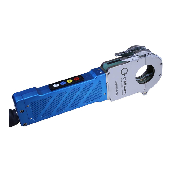
- Page 11 DEUTSCH ORBIWELD 38S, 76S, 115S, 170 Beschreibung BESCHREIBUNG POSITION BEZEICHNUNG FUNKTION Schwenkbügel Schweißkopf öffnen und schließen. Flip Cover Ausrichtung von Elektrode, Rohrstoß und Rohrversatz kontrollieren. Verschlüsse Schwenkbügel arretieren. Spanneinsatz Werkstücke ausrichten und spannen. Typenschild Zeigt Daten zum Schweißkopf an. Handgriff Schweißkopf festhalten.
- Page 12 DEUTSCH Einsatzmöglichkeiten ORBIWELD 38S, 76S, 115S, 170 EINSATZMÖGLICHKEITEN Typen EINHEIT ORBIWELD OW 38S OW 76S OW 115S OW 170 Rohr (Außendurchmesser) [mm] 3,0 ... 38,1 6,0 ... 77,0 20,0 ... 115,0 50,0 ... 170,0 min..max. [inch] 0.125 ... 1.5 0.25 ...
- Page 13 DEUTSCH ORBIWELD 38S, 76S, 115S, 170 Einsatzmöglichkeiten 4.2.4 Einsätze zum Bogenschweißen Zum Verschweißen von Standardbögen ohne geraden Schenkelansatz an Rohre. Bei Verwendung dieser Einsätze auf einer Schweißkopfseite (rechts oder links) wird lediglich der Gasschutz um den Bogen gewährleistet; ein Spannen erfolgt nicht, so dass der Bogen geheftet werden muss.
- Page 14 DEUTSCH Technische Daten ORBIWELD 38S, 76S, 115S, 170 4.2.7 Elektrodenadapter zum Innenschweißen Elektrodenadapter aus Messing erzeugt eine Schweißnaht im Werkstück-Innenstoß. ARTIKEL CODE Elektrodenadapter OW 38S Innenschweißen, Set 826 050 037 Elektrodenadapter OW 76S Innenschweißen, Set 827 050 039 Elektrodenadapter OW 115S Innenschweißen, Set 824 050 023 Elektrodenadapter OW 170 Innenschweißen...
- Page 15 DEUTSCH ORBIWELD 38S, 76S, 115S, 170 Technische Daten Abmessungen Orbitalum Tools GmbH D-78224 Singen www.orbitalum.com [REV. 20191120] OW_ORBIWELD_BA_821060201_00__INH-01_DE...
- Page 16 DEUTSCH Technische Daten ORBIWELD 38S, 76S, 115S, 170 ORBITALUM TOOLS GmbH D-78224 Singen www.orbitalum.com [REV. 20191120] OW_ORBIWELD_BA_821060201_00__INH-01_DE...
- Page 17 DEUTSCH ORBIWELD 38S, 76S, 115S, 170 Lagerung und Transport LAGERUNG UND TRANSPORT Bruttogewichte ARTIKEL GEWICHT* OW 38S [kg] 16,5 [lbs] 36.4 OW 76S [kg] 16,9 [lbs] 37,3 OW 115S [kg] 18,6 [lbs] 41.0 OW 170 [kg] 36,2 [lbs] 79.8 inkl. Transportkoffer Schweißkopf transportieren...
- Page 18 DEUTSCH Inbetriebnahme ORBIWELD 38S, 76S, 115S, 170 2. Schweißkopf am Handgriff aus Transportkoffer entnehmen. Einlagerung vorbereiten Vor der Einlagerung folgende Schritte durchführen: 1. Elektrode demontieren. 2. Ggf. Spanneinsätze demontieren. 3. Schweißkopf von der Schweißstromquelle trennen. 4. Verschlusskappen für Kühlflüssigkeit über Kühlflüssigkeitsanschlüsse stülpen.
- Page 19 DEUTSCH ORBIWELD 38S, 76S, 115S, 170 Inbetriebnahme INHALT WERKZEUGSET OW 38S OW 76S OW 115S OW 170 Sechskantschraubendreher 2,5x75 Sechskantschraubendreher 2,0x60 Schlitzschraubendreher 3,0x0,5x100 — — — Sechskantschraubendreher 3,0x75 — — — Elektrodenklemmschraube OW 38S — Elektrodenklemmschraube OW 76S/OW 115S —...
- Page 20 DEUTSCH Einrichtung und Montage ORBIWELD 38S, 76S, 115S, 170 EINRICHTUNG UND MONTAGE Vorgehensweise Einrichtung und Montage in folgender Reihenfolge durchführen: 1. Schweißstromquelle anschließen. 2. Spanneinsätze montieren. 3. Elektrode einrichten. 4. Werkstück spannen. 5. Gas- und Kühlflüssigkeits-Funktionstest durchführen. 6. Zubehör anschließen.
- Page 21 DEUTSCH ORBIWELD 38S, 76S, 115S, 170 Einrichtung und Montage Spanneinsätze montieren 1. Schweißkopf flach auf Auflagefläche positionieren. 2. Schwenkbügel öffnen. 3. Spanneinsatz (2) mit der Schrift nach außen einsetzen. Die Arretierung (1) muss dabei einschnappen. Elektrode einrichten Im Schweißkopf sind 2 Elektrodenbohrungen für unterschiedliche Elektrodendurchmesser vorhanden, die durch Elektro den- markierungen im Rotor gekennzeichnet sind.
- Page 22 DEUTSCH Einrichtung und Montage ORBIWELD 38S, 76S, 115S, 170 5. Sicherstellen, dass die Elektrode nicht in den Zahnraum des Rotors hineinragt, ggf. Elektrode kürzen. 6. Schweißstromquelle einschalten. 7. Taste END. 0POS drücken, um Rotor in Grund stellung (0-Position) zu bringen.
- Page 23 Der Schweißkopf ist einsatzbereit. Motor kalibrieren Sind mehrere Schweißköpfe des gleichen Typs im Einsatz, empfiehlt die Orbitalum Tools GmbH, die Motoren vor der Verwendung zu kalibrieren. Die Kalibrierung der Motoren gewährleistet, dass gespeicherte Programme auf allen Schweißköpfen das gleiche Ergebnis produzieren.
- Page 24 DEUTSCH Einrichtung und Montage ORBIWELD 38S, 76S, 115S, 170 8.10 Spanneinsätze demontieren 1. Schwenkbügel öffnen. 2. Spanneinsatz (1) durch Verschieben der Arretierung (2) nach außen lösen. 3. Spanneinsatz entnehmen. ORBITALUM TOOLS GmbH D-78224 Singen www.orbitalum.com [REV. 20191120] OW_ORBIWELD_BA_821060201_00__INH-01_DE...
- Page 25 DEUTSCH ORBIWELD 38S, 76S, 115S, 170 Bedienung BEDIENUNG Bedienelemente ELEMENT FUNKTION LED blinkt im schweißbereiten Zustand. LED leuchtet konstant während des Schweißprozesses. START Startet den Schweißprozess. START STOP • Einmaliges Drücken: Schweißprozess bricht sofort ab, Rotor wird gestoppt und STOP die Gasnachströmzeit wird aktiviert.
- Page 26 Regelmäßig X Regelmäßig den Schweißkopf mittels Druckluft ausblasen. (abhängig von Nutzung) Wöchentlich X Rotor mit Aceton reinigen. Alle 2 Jahre X Strom-Kühlflüssigkeitskabel durch den Service der Orbitalum Tools GmbH austauschen lassen. 10.3 Fehlerbehebung PROBLEM MÖGLICHE URSACHE BEHEBUNG Schweißprozess startet nicht.
- Page 27 DEUTSCH ORBIWELD 38S, 76S, 115S, 170 Instandhaltung und Störungsbeseitigung PROBLEM MÖGLICHE URSACHE BEHEBUNG Lichtbogen zieht zur Seite. Elektrode verschlissen. X Elektrode nachschleifen (siehe Kap. 10.4, S. 27). Elektrode falsch geschliffen. X Elektrode nachschleifen (siehe Kap. 8.5, S. 22). Schlechte Elektrodenqualität.
- Page 28 DEUTSCH Instandhaltung und Störungsbeseitigung ORBIWELD 38S, 76S, 115S, 170 ORBITALUM TOOLS GmbH D-78224 Singen www.orbitalum.com [REV. 20191120] OW_ORBIWELD_BA_821060201_00__INH-01_DE...
- Page 29 ENGLISH ORBIWELD 38S, 76S, 115S, 170 ENGLISH Table of contents About these instructions ..........31 4.2 Inserts ..............38 4.2.1 Clamping inserts ........38 1.1 Warning messages ..........31 4.2.2 Cavity inserts for moldings ......38 1.2 Further symbols and displays ....... 31 4.2.3 T-piece clamping inserts ......
-
Page 30: Table Of Contents
ENGLISH ORBIWELD 38S, 76S, 115S, 170 8.8 Configuring the welding procedure ...... 49 8.9 Calibrating the motor ..........49 8.10 Dismantling the clamping inserts ......50 Operation ............... 51 9.1 Operating elements ..........51 9.2 Setting the welding parameters ......51 9.3 Welding .............. - Page 31 ENGLISH ORBIWELD 38S, 76S, 115S, 170 About these instructions ABOUT THESE INSTRUCTIONS Warning messages The warning messages used in these instructions warn you of injuries or damage to property. X Always read and observe these warning messages! WARNING SYMBOL This is a warning symbol. It warns you of the danger of injury. In order to avoid injuries or death observe the measures marked with a safety sign.
- Page 32 ENGLISH Information and safety instructions for the responsible body ORBIWELD 38S, 76S, 115S, 170 INFORMATION AND SAFETY INSTRUCTIONS FOR THE RESPONSIBLE BODY Requirements for the responsible body Workshop/outdoor/field application: The responsible body is responsible for safety in the danger zone around the machine, and should allow only qualified personnel to enter the zone or operate the machine in the danger zone.
- Page 33 • We will properly dispose of devices and machines from Orbitalum Tools GmbH purchased after August 13th, 2005 if they are sent to us postage-paid.
- Page 34 ENGLISH Information and safety instructions for the responsible body ORBIWELD 38S, 76S, 115S, 170 Personnel qualification The orbital weld head may only be used by instructed personnel. • Minimum age: 18 years old. • No physical impairments. • Operation of the machine by underage persons only under supervision by a person authorized to issue instructions.
- Page 35 ENGLISH ORBIWELD 38S, 76S, 115S, 170 Information and safety instructions for the responsible body 2.7.2 Prick injury through pointed electrode Danger of being pricked by the electrode for the operator as well as for third parties while taking hold of the orbital weld head.
- Page 36 ENGLISH Information and safety instructions for the responsible body ORBIWELD 38S, 76S, 115S, 170 2.7.7 Tripping over the hose package If the hose package is under tension, there is the danger that persons may trip over it and be injured.
- Page 37 ENGLISH ORBIWELD 38S, 76S, 115S, 170 Description DESCRIPTION ITEM DESIGNATION FUNCTION Swivel clamp Open and close the weld head. Flip cover Check the alignment of the electrode, tube joint and tube offset. Latches Lock swivel clamp. Clamping insert Align and clamp workpieces.
- Page 38 ENGLISH Scope of application ORBIWELD 38S, 76S, 115S, 170 SCOPE OF APPLICATION Types UNIT ORBIWELD OW 38S OW 76S OW 115S OW 170 Tube OD [mm] 3.0 ... 38.1 6.0 ... 77.0 20.0 ... 115.0 50.0 ... 170.0 min..max.
- Page 39 ENGLISH ORBIWELD 38S, 76S, 115S, 170 Scope of application 4.2.4 Inserts for elbow welding For welding of standard elbows to tubes without straight side attachment. When using this inserts on a weld head side (left or right) only the gas protection around the elbow is guaranteed;...
- Page 40 ENGLISH Technical specifications ORBIWELD 38S, 76S, 115S, 170 4.2.7 Electrode adapter for inside welding Brass electrode adapter generates a weld seam in workpiece internal joint. ARTICLE CODE Electrode adapters OW 38S for inside welding, Set 826 050 037 Electrode adapters OW 76S for inside welding, Set...
- Page 41 ENGLISH ORBIWELD 38S, 76S, 115S, 170 Technical specifications Dimensions Orbitalum Tools GmbH D-78224 Singen www.orbitalum.com [REV. 20200115] OW_ORBIWELD_BA_821060201_00__INH-02_EN...
- Page 42 ENGLISH Technical specifications ORBIWELD 38S, 76S, 115S, 170 ORBITALUM TOOLS GmbH D-78224 Singen www.orbitalum.com [REV. 20200115] OW_ORBIWELD_BA_821060201_00__INH-02_EN...
- Page 43 ENGLISH ORBIWELD 38S, 76S, 115S, 170 Storage and transport STORAGE AND TRANSPORT Gross weights ARTICLE GEWICHT* OW 38S [kg] 16.5 [lbs] 36.4 OW 76S [kg] 16.9 [lbs] 37.3 OW 115S [kg] 18.6 [lbs] 41.0 OW 170 [kg] 36.2 [lbs] 79.8...
- Page 44 ENGLISH Initial operation ORBIWELD 38S, 76S, 115S, 170 2. Use the handle to remove the weld head from the transport case. Preparing storage Carry out the following steps before storage: 1. Remove the electrode. 2. If appropriate, remove the clamping inserts.
- Page 45 ENGLISH ORBIWELD 38S, 76S, 115S, 170 Initial operation CONTENTS TOOL SET OW 38S OW 76S OW 115S OW 170 Hexagon screwdriver 2.5x75 Hexagon screwdriver 2.0x60 Slot screwdriver 3.0x0.5x100 — — — Hexagon screwdriver 3.0x75 — — — Electrode clamping screw OW 38S —...
- Page 46 ENGLISH Set-up and assembly ORBIWELD 38S, 76S, 115S, 170 SETUP AND ASSEMBLY Procedure Carry out setting up and mounting in the following order: 1. Connect the welding power supply. 2. Mount the clamping inserts. 3. Set up the electrode. 4. Clamp the workpiece.
- Page 47 ENGLISH ORBIWELD 38S, 76S, 115S, 170 Set-up and assembly Mounting the clamping inserts 1. Position the weld head on the supporting area. 2. Open the swivel clamp. 3. Insert the clamping insert (2) with the writing facing outwards. The lock (1) has to latch in.
- Page 48 ENGLISH Set-up and assembly ORBIWELD 38S, 76S, 115S, 170 5. Ensure that the electrode does not project into the toothed space of the rotor. If necessary, shorten the electrode. 6. Switch on the welding power supply. 7. Press the END. 0POS button in order to bring the rotor to the home position (0-position).
-
Page 49: Configuring The Welding Procedure
Calibrating the motor If several weld heads of the same type are in use, Orbitalum Tools GmbH recommends that the motors be calibrated before use. The calibration of the motors ensures that saved programs on all the weld heads produce the same result. -
Page 50: Dismantling The Clamping Inserts
ENGLISH Set-up and assembly ORBIWELD 38S, 76S, 115S, 170 8.10 Dismantling the clamping inserts 1. Open the swivel clamp. 2. Loosen the clamping insert (1) by moving the lock (2) outwards. 3. Remove the clamping insert. ORBITALUM TOOLS GmbH D-78224 Singen www.orbitalum.com... -
Page 51: Operation
ENGLISH ORBIWELD 38S, 76S, 115S, 170 Operation OPERATION Operating elements ELEMENT FUNCTION LED flashes in ready-to-weld state. LED lights up constantly during the welding process. START Starts the welding process. START STOP • Pressing once: Welding process aborts immediately, rotor is stopped and the STOP gas post purge time is activated. -
Page 52: 10. Maintenance And Troubleshooting
Regularly (depending on usage) X Blow out the weld head regularly by means of compressed air. Weekly X Clean the rotor with acetone. Every 2 years X Have the power-cooling liquid cable replaced by the Service of Orbitalum Tools GmbH. 10.3 Troubleshooting PROBLEM... -
Page 53: Grinding The Electrodes
ENGLISH ORBIWELD 38S, 76S, 115S, 170 Maintenance and troubleshooting PROBLEM POSSIBLE CAUSE REMEDY Arc tends to one side. Electrode worn. X Regrind the electrode (see chap. 10.4, p. 53). Electrode ground incorrectly. X Regrind the electrode (see chap. 10.4, p. 53). - Page 54 ENGLISH Maintenance and troubleshooting ORBIWELD 38S, 76S, 115S, 170 ORBITALUM TOOLS GmbH D-78224 Singen www.orbitalum.com [REV. 20200115] OW_ORBIWELD_BA_821060201_00__INH-02_EN...
- Page 55 FRANçAIS ORBIWELD 38S, 76S, 115S, 170 FRANçAIS Sommaire Concernant le présent manuel d'utilisation ....57 4.2 Coquilles de serrage..........64 4.2.1 Coquilles de serrage ......... 64 1.1 Consignes d’avertissement ........57 4.2.2 Coquilles alvéolées pour pièces de 1.2 Autres pictogrammes et signalétiques ....57 forme ............
- Page 56 FRANçAIS ORBIWELD 38S, 76S, 115S, 170 8.7 Raccordement des accessoires ......75 8.8 Configuration du programme de soudage .... 75 8.9 Calibrage du moteur ..........75 8.10 Démontage des coquilles de serrage ....76 Utilisation............... 77 9.1 Eléments de commande ........77 9.2 Réglage des paramètres de soudage ....
- Page 57 FRANçAIS ORBIWELD 38S, 76S, 115S, 170 Concernant le présent manuel d'utilisation CONCERNANT LE PRÉSENT MANUEL D'UTILISATION Consignes d’avertissement Les indications d'avertissement utilisées dans ce mode d'emploi avertissent de blessures ou de dommages matériels. X Toujours lire et respecter les indications d'avertissement ! PICTOGRAMME Ce pictogramme est un pictogramme de danger.
- Page 58 FRANçAIS Informations opérateur et consignes de sécurité ORBIWELD 38S, 76S, 115S, 170 INFORMATIONS OPÉRATEUR ET CONSIGNES DE SÉCURITÉ Obligations opérateur Utilisation en atélier/extérieur/terrain: L'opérateur est responsable de la sécurité dans la zone de dangers de la machine et n'autorise l'accès dans la zone de dangers et l'utilisation de la machine uniquement à du personnel formé.
- Page 59 • Pour les appareils et machines d’Orbitalum Tools GmbH que vous avez achetés après le 13 août 2005, nous nous chargeons d’une élimination dans les règles de l’art après une livraison sans frais pour nous.
- Page 60 FRANçAIS Informations opérateur et consignes de sécurité ORBIWELD 38S, 76S, 115S, 170 Qualification du personnel La têtes de soudage orbital peut uniquement être utilisée par du personnel averti. • Age minimum: 18 ans. • Sans handicaps physiques. • Commande de la machine par des mineurs d’âge uniquement sous la surveillance d’une personne habilitée.
- Page 61 FRANçAIS ORBIWELD 38S, 76S, 115S, 170 Informations opérateur et consignes de sécurité 2.7.2 Blessure de poinçonnement avec l’électrode pointue Lors de la prise de la tête de soudage orbital, il y a danger tant pour l’opérateur que pour des tiers de se piquer avec l’électrode.
- Page 62 FRANçAIS Informations opérateur et consignes de sécurité ORBIWELD 38S, 76S, 115S, 170 2.7.7 Trébuchement sur le paquet de flexibles Lorsque le paquet de flexibles est en traction, il y a danger que des personnes trébuchent et se blessent. En outre, le connecteur mâle peut être arraché, ce qui peut dans le pire des cas donner lieu à un arc électrique entre la fiche et l’installation de soudage orbital.
- Page 63 FRANçAIS ORBIWELD 38S, 76S, 115S, 170 Description DESCRIPTION POSITION DÉSIGNATION FONCTION Support pivotant Ouverture et fermeture de la tête de soudage. Flip Cover Contrôler l'alignement de l'électrode, du joint de tube et du décalage de tube. Fermetures Bloquer le support pivotant.
- Page 64 FRANçAIS Possibilités d'utilisation ORBIWELD 38S, 76S, 115S, 170 POSSIBILITÉS D'UTILISATION Types NATURE UNITÉ ORBIWELD OW 38S OW 76S OW 115S OW 170 Diamètre ext. des tubes [mm] 3,0 ... 38,1 6,0 ... 77,0 20,0 ... 115,0 50,0 ... 170,0 min..max.
- Page 65 FRANçAIS ORBIWELD 38S, 76S, 115S, 170 Possibilités d'utilisation 4.2.4 Coquilles pour soudage en angle Pour le soudage de coudes standards sans partie droit sur tube. L’utilisation de cette coquilles sur un côté de la tête de soudage (droit ou gauche) permet simplement de garantir la protection gazeuse autour du coude, il n’...
- Page 66 FRANçAIS Données techniques ORBIWELD 38S, 76S, 115S, 170 4.2.7 Adaptateur d‘électrodespour la soudure intérieur L’adaptateur d’électrode en laiton génère un cordon de soudure dans le joint intérieur de la pièce. ARTICLE RÉF. Adaptateur d‘électrodes OW 38S soudure intérieur, set 826 050 037 Adaptateur d‘électrodes OW 76S soudure intérieur, set...
- Page 67 FRANçAIS ORBIWELD 38S, 76S, 115S, 170 Données techniques Dimensions Orbitalum Tools GmbH D-78224 Singen www.orbitalum.com [REV. 20200115] OW_ORBIWELD_BA_821060201_00__INH-03_FR...
- Page 68 FRANçAIS Données techniques ORBIWELD 38S, 76S, 115S, 170 ORBITALUM TOOLS GmbH D-78224 Singen www.orbitalum.com [REV. 20200115] OW_ORBIWELD_BA_821060201_00__INH-03_FR...
- Page 69 FRANçAIS ORBIWELD 38S, 76S, 115S, 170 Stockage et transport STOCKAGE ET TRANSPORT Poids bruts ARTICLE POIDS* OW 38S [kg] 16,5 [lbs] 36.4 OW 76S [kg] 16,9 [lbs] 37,3 OW 115S [kg] 18,6 [lbs] 41.0 OW 170 [kg] 36,2 [lbs] 79.8 avec coffret de transport Transport de la tête de soudage...
- Page 70 FRANçAIS Mise en service ORBIWELD 38S, 76S, 115S, 170 2. Enlever la tête de soudage de la coffret de transport par la poignée. Préparation du stockage Avant le stockage, effectuer les activités suivantes: 1. Démonter l’électrode. 2. Le cas échéant, démonter les coquilles de serrage.
- Page 71 FRANçAIS ORBIWELD 38S, 76S, 115S, 170 Mise en service SOMMAIRE JEU D’OUTILS OW 38S OW 76S OW 115S OW 170 Tournevis six pans 2,5x75 Tournevis six pans 2,0x60 Tournevis à fente 3,0x0,5x100 — — — Tournevis six pans 3,0x75 —...
- Page 72 FRANçAIS Installation et montage ORBIWELD 38S, 76S, 115S, 170 INSTALLATION ET MONTAGE Procédure Effectuer l’ajustage et le montage dans l’ordre suivant: 1. Raccorder le générateur de soudage. 2. Monter les coquilles de serrage. 3. Ajuster l’électrode. 4. Serrer la pièce.
- Page 73 FRANçAIS ORBIWELD 38S, 76S, 115S, 170 Installation et montage Monter les coquilles de serrage 1. Positionner la tête de soudage à plat sur la surface d’appui. 2. Ouvrir le support pivotant. 3. Utiliser la coquille de serrage (2) avec l’inscription vers l’extérieur.
- Page 74 FRANçAIS Installation et montage ORBIWELD 38S, 76S, 115S, 170 5. S’assurer que l’électrode ne dépasse pas dans l’espace des dents du rotor, le cas échéant raccourcir l’électrode. 6. Enclencher le générateur de soudage. 7. Appuyer sur la touche END. 0POS pour amener le rotor dans la position de base (position 0).
- Page 75 Calibrage du moteur Si plusieurs têtes de soudage du même type sont utilisées, Orbitalum Tools GmbH recommande de calibrer les moteurs avant l’utilisation. Le calibrage des moteurs garantit que les programmes enregistrés produiront le même résultat sur toutes les têtes de soudage.
- Page 76 FRANçAIS Installation et montage ORBIWELD 38S, 76S, 115S, 170 8.10 Démontage des coquilles de serrage 1. Ouvrir le support pivotant. 2. Desserrer la coquille de serrage (1) en déplçant le blocage (2) vers l’extérieur. 3. Retirer la coquille de serrage.
- Page 77 FRANçAIS ORBIWELD 38S, 76S, 115S, 170 Utilisation UTILISATION Eléments de commande ELÉMENT FONCTION La LED clignote dans l'état prêt à souder. LED s'allume en continu pendant le processus de soudage. START Démarre le processus de soudage. START STOP • Appuyer une fois: le processus de soudage s'interrompt immédiatement, le STOP rotor est arrêté...
- Page 78 FRANçAIS Maintenance/réparation et dépannage ORBIWELD 38S, 76S, 115S, 170 10. MAINTENANCE/RÉPARATION ET DÉPANNAGE 10.1 Indications d’entretien X Ne pas utiliser de lubrifiant ni d’antigrippant. X Veiller à ce qu’il n’y ait pas de particules de saleté ni de petites pièces qui parviennent dans le réducteur (intérieur de la tête) (du fait du type de construction, le réducteur est ouvert côté...
- Page 79 FRANçAIS ORBIWELD 38S, 76S, 115S, 170 Maintenance/réparation et dépannage PROBLÈME CAUSES POSSIBLES REMÈDE L'arc électrique dévie latéra- Electrode usée. X Affûter l'électrode (voir chap. 10.4, p. 79). lement. Electrode mal affûtée. X Affûter l'électrode (voir chap. 10.4, p. 79). Mauvaise qualité d'électrode.
- Page 80 FRANçAIS ORBIWELD 38S, 76S, 115S, 170 ORBITALUM TOOLS GmbH D-78224 Singen www.orbitalum.com [REV. 20200115] OW_ORBIWELD_BA_821060201_00__INH-03_FR...
- Page 81 ITALIANO ORBIWELD 38S, 76S, 115S, 170 ITALIANO Indice Informazioni sul manuale ..........83 4.2 Collari ..............90 4.2.1 Collari di serraggio ........90 1.1 Avvertenze ............. 83 4.2.2 Collari a camera per saldatura 1.2 Altri simboli e segnali ..........83 di semilavorati ...........
- Page 82 ITALIANO ORBIWELD 38S, 76S, 115S, 170 8.6 Esecuzione del test di funzionamento del gas e del liquido di raffreddamento ....101 8.7 Collegamento di accessori ........101 8.8 Configurazione del programma di saldatura ..101 8.9 Calibrazione del motore ........101 8.10 Smontaggio dei collari di serraggio ....
-
Page 83: Informazioni Sul Manuale
ITALIANO ORBIWELD 38S, 76S, 115S, 170 Informazioni sul manuale INFORMAZIONI SUL MANUALE Avvertenze Gli avvertimenti utilizzati nel presente manuale di istruzioni contribuiscono ad evitare lesioni o danni materiali. X Leggere ed attenersi agli avvertimenti in qualsiasi caso! AVVERTENZA Essi avvertono del pericolo di lesioni. Per evitare lesioni, anche letali, adottare i provvedimenti indicati dai simboli di sicurezza. -
Page 84: Informazioni Per L'utilizzatore E Norme Di Sicurezza
ITALIANO Informazioni per l'utilizzatore e norme di sicurezza ORBIWELD 38S, 76S, 115S, 170 INFORMAZIONI PER L'UTILIZZATORE E NORME DI SICUREZZA Obblighi del utilizzatore Impiego all’esterno/in cantiere/in officina: L’utilizzatore è responsabile per la sicurezza nella zona pericolosa della macchina e consente soltanto al personale autorizzato l’accesso a tale zona e l’uso della macchina. -
Page 85: Limiti Della Macchina
è responsabile l'utilizzatore. A tal fine si prega di rivolgersi ad un'azienda di smaltimento specializzata nelle proprie vicinanze. • Importante per la Germania: gli apparecchi e le macchine della Orbitalum Tools GmbH non devono essere smaltiti tramite i centri di smaltimento comunali, in quanto vengono impiegati solo nel settore industriale. -
Page 86: Qualificazione Del Personale
ITALIANO Informazioni per l'utilizzatore e norme di sicurezza ORBIWELD 38S, 76S, 115S, 170 Qualificazione del personale La testa per saldatura orbitale deve essere utilizzata solo da personale qualificato. • Età minima: 18 anni. • Assenza di menomazioni fisiche. • Uso della macchina da parte di minorenni solo sotto la supervisione di una persona con facoltà direttive. -
Page 87: Lesioni Dovute Agli Elettrodi Acuminati
ITALIANO ORBIWELD 38S, 76S, 115S, 170 Informazioni per l'utilizzatore e norme di sicurezza 2.7.2 Lesioni dovute agli elettrodi acuminati Quando si afferra la testa per saldatura orbitale, sussiste il pericolo di riportare lesioni dall’elettrodo sia per l’operatore sia per terzi. -
Page 88: Incespicamento Sul Fascio Cavi
ITALIANO Informazioni per l'utilizzatore e norme di sicurezza ORBIWELD 38S, 76S, 115S, 170 2.7.7 Incespicamento sul fascio cavi Se il fascio cavi si trova sotto tensione meccanica, sussiste il pericolo di incespicare su di esso e di riportare lesioni. Inoltre il connettore a spina può fuoriuscire, per cui nel peggiore dei casi si può formare un arco elettrico tra il connettore a spina stesso e il sistema di saldatura orbitale. -
Page 89: Descrizione
ITALIANO ORBIWELD 38S, 76S, 115S, 170 Descrizione DESCRIZIONE POSIZIONE COMPONENTE FUNZIONE Supporto superiore Aprire e chiudere la testa per saldatura. Copertura a cerniera Controllare il posizionamento dell'elettrodo, del giunto del tubo e del disallineamento del tubo. Elementi di chiusura Bloccare il supporto superiore. -
Page 90: Possibilità Di Applicazione
ITALIANO Possibilità di applicazione ORBIWELD 38S, 76S, 115S, 170 POSSIBILITÀ DI APPLICAZIONE Tipi ORBIWELD OW 38S OW 76S OW 115S OW 170 Diametro esterno tubo [mm] 3,0 ... 38,1 6,0 ... 77,0 20,0 ... 115,0 50,0 ... 170,0 min..max. -
Page 91: Collari Per Saldatura Di Curve
ITALIANO ORBIWELD 38S, 76S, 115S, 170 Possibilità di applicazione 4.2.4 Collari per saldatura di curve Per la saldatura di curve standard senza codolo. Con l‘impiego di questo collare su un lato della testa per saldatura (destra o sinistra) è garantito solamente il riferimento ma non il fissaggio della curva. -
Page 92: Adattatori Elettrodi Per Saldatura Dall' Interno
ITALIANO Dati tecnici ORBIWELD 38S, 76S, 115S, 170 4.2.7 Adattatori elettrodi per saldatura dall‘ interno L’adattatore per elettrodo di ottone genera un cordone di saldatura nel giunto interno del pezzo da saldare. ARTICOLO CODICE Adattatore elettrodi OW 38S per saldatura dall‘ interno (set) 826 050 037 Adattatore elettrodi OW 76S per saldatura dall‘... -
Page 93: Dimensioni
ITALIANO ORBIWELD 38S, 76S, 115S, 170 Dati tecnici Dimensioni Orbitalum Tools GmbH D-78224 Singen www.orbitalum.com [REV. 20200115] OW_ORBIWELD_BA_821060201_00__INH-04_IT... - Page 94 ITALIANO Dati tecnici ORBIWELD 38S, 76S, 115S, 170 ORBITALUM TOOLS GmbH D-78224 Singen www.orbitalum.com [REV. 20200115] OW_ORBIWELD_BA_821060201_00__INH-04_IT...
-
Page 95: Stoccaggio E Trasporto
ITALIANO ORBIWELD 38S, 76S, 115S, 170 Stoccaggio e trasporto STOCCAGGIO E TRASPORTO Pesi lordi ARTICOLO PESO* OW 38S [kg] 16,5 [lbs] 36.4 OW 76S [kg] 16,9 [lbs] 37,3 OW 115S [kg] 18,6 [lbs] 41.0 OW 170 [kg] 36,2 [lbs] 79.8... -
Page 96: Preparazione Dell'immagazzinamento
ITALIANO Messa in funzione ORBIWELD 38S, 76S, 115S, 170 2. Prelevare la testa per saldatura dalla valigetta di trasporto afferrandola solo per l’impugnatura Preparazione dell’immagazzinamento Prima dell’immagazzinamento eseguire le seguenti operazioni: 1. Smontare l’elettrodo. 2. Smontare eventualmente i collari di serraggio. -
Page 97: Accessori (Opzionali)
ITALIANO ORBIWELD 38S, 76S, 115S, 170 Messa in funzione CONTENUTO SET DI CHIAVI DI SERVIZIO OW 38S OW 76S OW 115S OW 170 Cacciavite per viti a testa esagonale 2,5x75 Cacciavite per viti a testa esagonale 2,0x60 Cacciavite con punta piatta 3,0x0,5x100 —... -
Page 98: Installazione E Montaggio
ITALIANO Installazione e montaggio ORBIWELD 38S, 76S, 115S, 170 INSTALLAZIONE E MONTAGGIO Procedimento Eseguire l’allestimento e il montaggio nell’ordine seguente: 1. Collegare il generatore della corrente di saldatura. 2. Montare i collari di serraggio. 3. Montare e posizionare l’elettrodo. 4. Serrare il pezzo da saldare. -
Page 99: Montaggio Dei Collari Di Serraggio
ITALIANO ORBIWELD 38S, 76S, 115S, 170 Installazione e montaggio Montaggio dei collari di serraggio 1. Posizionare la testa per saldatura in piano sulla superficie d’appoggio. 2. Aprire il supporto superiore. 3. Applicare il collare di serraggio (2) con la scritta rivolta verso l’esterno. -
Page 100: Serraggio Dei Pezzi Da Saldare
ITALIANO Installazione e montaggio ORBIWELD 38S, 76S, 115S, 170 5. Verificare che l’elettrodo non sporga nello spazio dei denti del rotore; accorciarlo, se necessario. 6. Accendere il generatore della corrente di saldatura. 7. Premere il tasto END. 0POS per portare il rotore in posizione di base (posizione 0). -
Page 101: Esecuzione Del Test Di Funzionamento Del Gas E Del Liquido Di Raffreddamento
Calibrazione del motore Se si impiegano più teste per saldatura dello stesso tipo, Orbitalum Tools GmbH consiglia di calibrare i motori prima dell’uso. La calibrazione dei motori garantisce che i programmi memorizzati producano lo stesso risultato per tutte le teste per saldatura. -
Page 102: Smontaggio Dei Collari Di Serraggio
ITALIANO Installazione e montaggio ORBIWELD 38S, 76S, 115S, 170 8.10 Smontaggio dei collari di serraggio 1. Aprire il supporto superiore. 2. Sbloccare il collare di serraggio (1) spostando l’elemento di bloccaggio (2) verso l’esterno. 3. Togliere il collare di serraggio ORBITALUM TOOLS GmbH D-78224 Singen www.orbitalum.com... -
Page 103: Funzionamento
ITALIANO ORBIWELD 38S, 76S, 115S, 170 Funzionamento FUNZIONAMENTO Elementi di comando ELEMENTO FUNZIONE Il LED lampeggia quando il sistema è pronto per la saldatura. Il LED resta acceso durante il processo di saldatura. START Avvia il processo di saldatura. START STOP •... -
Page 104: 10. Manutenzione E Risoluzione Delle Anomalie
ITALIANO Manutenzione e risoluzione delle anomalie ORBIWELD 38S, 76S, 115S, 170 10. MANUTENZIONE E RISOLUZIONE DELLE ANOMALIE 10.1 Avvertenze per la cura del sistema X Non utilizzare lubrificanti. X Prestare attenzione a non far penetrare particelle di sporco o minuteria all’interno del riduttore (all’interno della testa) (il riduttore è... -
Page 105: Rifacimento Della Punta Degli Elettrodi
ITALIANO ORBIWELD 38S, 76S, 115S, 170 Manutenzione e risoluzione delle anomalie PROBLEMA POSSIBILE CAUSA RIMEDIO L'arco elettrico è erratico. Elettrodo consumato. X Rifare la punta all'elettrodo (v. cap. 10.4, p. 105). Punta dell'elettrodo fatta scorrettamente. X Rifare la punta all'elettrodo (v. - Page 106 ITALIANO ORBIWELD 38S, 76S, 115S, 170 ORBITALUM TOOLS GmbH D-78224 Singen www.orbitalum.com [REV. 20200115] OW_ORBIWELD_BA_821060201_00__INH-04_IT...
- Page 107 ESPAñOL ORBIWELD 38S, 76S, 115S, 170 ESPAñOL Índice Sobre estas instrucciones ..........109 4.1 Tipos ..............116 1.1 Advertencias ............109 4.2 Insertos ..............116 4.2.1 Insertos de sujeción .........116 1.2 Más símbolos y marcas ........109 4.2.2 Insertos de cámara para piezas 1.3 Abreviaturas ............
- Page 108 ESPAñOL ORBIWELD 38S, 76S, 115S, 170 8.5 Sujeción de la pieza de trabajo ......126 8.6 Realización de la prueba de funcionamiento de gas y de líquido refrigerante ......127 8.7 Conexión de los accesorios ......... 127 8.8 Configuración del programa de soldadura ..127 8.9 Calibración del motor..........
-
Page 109: Sobre Estas Instrucciones
ESPAñOL ORBIWELD 38S, 76S, 115S, 170 Sobre estas instrucciones SOBRE ESTAS INSTRUCCIONES Advertencias Las indicaciones de advertencia utilizadas en estas instrucciones advierten ante posibles lesiones o daños materiales. X ¡Lea y tenga en cuenta siempre estas indicaciones de advertencia! SÍMBOLO DE Esto es un símbolo de advertencia. -
Page 110: Información Del Operador E Indicaciones De Seguridad
ESPAñOL Información del operador e indicaciones de seguridad ORBIWELD 38S, 76S, 115S, 170 INFORMACIÓN DEL OPERADOR E INDICACIONES DE SEGURIDAD Obligaciones del operador Utilización en el taller/exterior/de campo: El operador es responsable de la seguridad en la zona de peligro de la máqui- na y solo permite al personal instruido permanecer y usar la máquina en la zona de peligro. -
Page 111: Límites De La Máquina
• Los dispositivos y máquinas de Orbitalum Tools GmbH que hayan sido adquiridos con posterioridad al 13 de agosto de 2005, serán eliminados de forma profesional después de su respectiva entrega gratuita para nosotros. -
Page 112: Cualificación Del Personal
ESPAñOL Información del operador e indicaciones de seguridad ORBIWELD 38S, 76S, 115S, 170 Cualificación del personal El cabezal de soldadura orbital solo debe utilizarse por personal instruido. • Edad mínima: 18 años. • Sin discapacidades físicas. • El manejo de la máquina por menores de edad solo deberá tener lugar bajo la vigilancia de un supervisor. -
Page 113: Peligro De Sufrir Pinchazos Por Electrodos Puntiagudos
ESPAñOL ORBIWELD 38S, 76S, 115S, 170 Información del operador e indicaciones de seguridad 2.7.2 Peligro de sufrir pinchazos por electrodos puntiagudos Al sujetar el cabezal de soldadura orbital existe el peligro de sufrir pinchazos en el electrodo, tanto para el operador como también para terceros. -
Page 114: Tropiezos Con El Paquete De Mangueras
ESPAñOL Información del operador e indicaciones de seguridad ORBIWELD 38S, 76S, 115S, 170 X Antes de realizar trabajos en el cabezal de soldadura orbital o antes de embalarlo en el maletín de transporte, deberá esperar hasta que las superficies se hayan enfriado a una temperatura inferior a 50 °C. -
Page 115: Descripción
ESPAñOL ORBIWELD 38S, 76S, 115S, 170 Descripción DESCRIPCIÓN POSICIÓN DENOMINACIÓN FUNCIÓN Arco giratorio Abrir y cerrar el cabezal de soldadura. Mirilla Orientación del electrodo, controlar la juntura del tubo y el desplazamiento del tubo. Cierres Bloquear el arco giratorio. Inserto de sujeción Orientar y sujetar las piezas de trabajo. -
Page 116: Opciones De Aplicación
ESPAñOL Opciones de aplicación ORBIWELD 38S, 76S, 115S, 170 OPCIONES DE APLICACIÓN Tipos TIPO UNIDAD ORBIWELD OW 38S OW 76S OW 115S OW 170 Diámetro ext. de tubo [mm] 3,0 ... 38,1 6,0 ... 77,0 20,0 ... 115,0 50,0 ... 170,0 mín. -
Page 117: Insertos Para La Soldadura Por Arco
ESPAñOL ORBIWELD 38S, 76S, 115S, 170 Opciones de aplicación 4.2.4 Insertos para la soldadura por arco Para la soldadura de arcos estándar sin apoyo de lado recto en el tubo. Para la utilización de estos insertos en un lado del cabezal de soldadura (a la derecha o a la izquierda) se garantiza solo la protección contra el gas, alrededor del arco;... -
Page 118: Adaptador De Electrodos Para Soldadura Interior
ESPAñOL Datos técnicos ORBIWELD 38S, 76S, 115S, 170 4.2.7 Adaptador de electrodos para soldadura interior El adaptador de electrodos de latón genera un cordón de soldadura en la unión interior de la pieza de trabajo. ARTÍCULO CÓDIGO Adaptador de electrodos OW 38S para soldadura interior, juego... -
Page 119: Dimensiones
ESPAñOL ORBIWELD 38S, 76S, 115S, 170 Datos técnicos Dimensiones Orbitalum Tools GmbH D-78224 Singen www.orbitalum.com [REV. 20200115] OW_ORBIWELD_BA_821060201_00__INH-05_ES... - Page 120 ESPAñOL Datos técnicos ORBIWELD 38S, 76S, 115S, 170 ORBITALUM TOOLS GmbH D-78224 Singen www.orbitalum.com [REV. 20200115] OW_ORBIWELD_BA_821060201_00__INH-05_ES...
-
Page 121: Almacenamiento Y Transporte
ESPAñOL ORBIWELD 38S, 76S, 115S, 170 Almacenamiento y transporte ALMACENAMIENTO Y TRANSPORTE Pesos brutos ARTÍCULO PESO* OW 38S [kg] 16,5 [lbs] 36.4 OW 76S [kg] 16,9 [lbs] 37,3 OW 115S [kg] 18,6 [lbs] 41.0 OW 170 [kg] 36,2 [lbs] 79.8 incl. -
Page 122: Preparación Del Almacenamiento
ESPAñOL Puesta en servicio ORBIWELD 38S, 76S, 115S, 170 2. Extraiga el cabezal de soldadura del maletín de transporte sujetándolo por el mango. Preparación del almacenamiento Antes del almacenamiento deberá llevar a cabo los siguientes pasos: 1. Desmonte el electrodo. -
Page 123: Accesorios (Opcional)
ESPAñOL ORBIWELD 38S, 76S, 115S, 170 Puesta en servicio CONTENIDO JUEGO DE HERRAMIENTAS OW 38S OW 76S OW 115S OW 170 Destornillador hexagonal 1,5x50 Destornillador hexagonal 2,5x75 Destornillador hexagonal 2,0x60 Destornillador plano 3,0x0,5x100 — — — Destornillador hexagonal 3,0x75 —... -
Page 124: Instalación Y Montaje
ESPAñOL Instalación y montaje ORBIWELD 38S, 76S, 115S, 170 INSTALACIÓN Y MONTAJE Procedimiento Realice el ajuste y el montaje en el siguiente orden: 1. Conecte la fuente de corriente de soldadura. 2. Monte los insertos de sujeción. 3. Ajuste el electrodo. -
Page 125: Montaje De Los Insertos De Sujeción
ESPAñOL ORBIWELD 38S, 76S, 115S, 170 Instalación y montaje Montaje de los insertos de sujeción 1. Coloque el cabezal de soldadura en posición plana sobre la superficie de apoyo. 2. Abra el arco giratorio. 3. Inserte el inserto de sujeción (2) con la rotulación hacia el exterior. -
Page 126: Sujeción De La Pieza De Trabajo
ESPAñOL Instalación y montaje ORBIWELD 38S, 76S, 115S, 170 5. Asegúrese de que el electrodo no penetre en el espacio dentado del rotor y, en caso necesario, acorte el electrodo. 6. Conecte la fuente de corriente de soldadura. 7. Pulse la tecla END. 0POS para desplazar el rotor a la posición inicial (posición 0). -
Page 127: Realización De La Prueba De Funcionamiento De Gas Y De Líquido Refrigerante
Calibración del motor Si se están utilizando varios cabezales de soldadura del mismo tipo, Orbitalum Tools GmbH recomienda calibrar los motores antes de la utilización. La calibración de los motores garantiza que los programas guardados produzcan el mismo resultado en todos los cabezales de soldadura. -
Page 128: Desmontaje De Los Insertos De Sujeción
ESPAñOL Instalación y montaje ORBIWELD 38S, 76S, 115S, 170 8.10 Desmontaje de los insertos de sujeción 1. Abra el arco giratorio. 2. Suelte el inserto de sujeción (1) desplazando el bloqueo (2) hacia fuera. 3. Retire el inserto de sujeción. -
Page 129: Manejo
ESPAñOL ORBIWELD 38S, 76S, 115S, 170 Manejo MANEJO Elementos de manejo ELEMENTO FUNCIÓN El LED parpadea en estado preparado para la soldadura. El LED de forma constante durante el proceso de soldadura. START Inicia el proceso de soldadura. START STOP •... -
Page 130: 10. Mantenimiento, Resolución De Problemas
Semanal X Limpiar el rotor con acetona. Cada 2 años X Solicitar al servicio de asistencia de Orbitalum Tools GmbH la sustitución del cable de corriente del líquido refrigerante. ORBITALUM TOOLS GmbH D-78224 Singen www.orbitalum.com [REV. 20200115] OW_ORBIWELD_BA_821060201_00__INH-05_ES... -
Page 131: Solución De Errores
ESPAñOL ORBIWELD 38S, 76S, 115S, 170 Mantenimiento, resolución de problemas 10.3 Solución de errores PROBLEMA POSIBLE CAUSA ELIMINACIÓN El proceso de soldadura no No hay suministro de gas y de líquido X Compruebe las conexiones a la fuente de se inicia. -
Page 132: Rectificado De Los Electrodos
ESPAñOL Mantenimiento, resolución de problemas ORBIWELD 38S, 76S, 115S, 170 10.4 Rectificado de los electrodos X Rectifique el electrodo únicamente en sentido longitudinal. X Después del rectificado del electrodo, parta la punta de acuerdo con el siguiente dibujo. 60° Ø... - Page 133 NEDERLANDS ORBIWELD 38S, 76S, 115S, 170 NEDERLANDS Inhoudsopgave Verklaring handleiding ..........135 4.2.1 Opspanbekken ........142 4.2.2 Kamerinzetten voor vormdelen ....142 1.1 Waarschuwingen ..........135 4.2.3 T-stuk opspanbekken ......142 4.2.4 Inzetten voor booglassen ......143 1.2 Verdere symbolen en aanduidingen ....135 4.2.5 Elektrode-adapter van messing ....
- Page 134 NEDERLANDS ORBIWELD 38S, 76S, 115S, 170 8.8 Lasprogramma configureren....... 153 8.9 Motor kalibreren ..........153 8.10 Opspanbekken demonteren ....... 154 Bediening ..............155 9.1 Bedieningselementen ......... 155 9.2 Lasparameters instellen ........155 9.3 Lassen ..............155 10. Service en verhelpen van storingen......156 10.1 Onderhoudsinstructies ........
-
Page 135: Verklaring Handleiding
NEDERLANDS ORBIWELD 38S, 76S, 115S, 170 Verklaring handleiding VERKLARING HANDLEIDING Waarschuwingen De in deze handleiding gebruikte waarschuwingen maken u attent op mogelijk letsel of materiële schade. X Lees al deze waarschuwingen en neem ze in acht! WAARSCHUWING Dit is een waarschuwingsymbool. Het waarschuwt voor gevaar voor letsel. Volg de met het SYMBOOL veiligheidssymbool gemarkeerde maatregelen op om letsel of de dood te voorkomen. -
Page 136: Informatie Voor De Exploitant En Veiligheidsaanwijzingen
NEDERLANDS Informatie voor de exploitant en veiligheidsaanwijzingen ORBIWELD 38S, 76S, 115S, 170 INFORMATIE VOOR DE EXPLOITANT EN VEILIG HEIDSAANWIJZINGEN Plichten van de exploitant Gebruik in de werkplaats/buiten/in het veld: De exploitant is verantwoordelijk voor de veiligheid in de gevarenzone van de machine en moet ervoor zorgen dat alleen geschoold personeel in de gevarenzone van de machine kan komen en de machine bedient. -
Page 137: Grenzen Van De Machine
(vlg. RL 2012/19/EG) milieubewuste afvoer en bescherming van de menselijke gezondheid. • Apparaten en machines van Orbitalum Tools GmbH, die u na 13 augustus 2005 hebt verworven, zullen wij, wanneer deze voor ons kosteloos worden teruggestuurd, op de juiste wijze afvoeren. -
Page 138: Personeelskwalificaties
NEDERLANDS Informatie voor de exploitant en veiligheidsaanwijzingen ORBIWELD 38S, 76S, 115S, 170 Personeelskwalificaties De orbitaallaskop mag uitsluitend worden gebruikt door geïnstrueerd personeel. • Minimumleeftijd: 18 jaar. • Geen lichamelijke beperkingen. • Bediening van de machine door minderjarigen uitsluitend onder toezicht van een bevoegde persoon. -
Page 139: Steken Door Scherpe Elektrode
NEDERLANDS ORBIWELD 38S, 76S, 115S, 170 Informatie voor de exploitant en veiligheidsaanwijzingen 2.7.2 Steken door scherpe elektrode Bij het vastpakken van de orbitaallaskop bestaat zowel voor de bediener als voor derden het gevaar van steken door de elektrode. X Pak de orbitaallaskop niet vast bij de elektrode. -
Page 140: Struikelen Over Het Slangenpakket
NEDERLANDS Informatie voor de exploitant en veiligheidsaanwijzingen ORBIWELD 38S, 76S, 115S, 170 2.7.7 Struikelen over het slangenpakket Wanneer het slangenpakket onder trekspanning staat, bestaat het gevaar dat personen daarover struikelen en zich verwonden. Bovendien kan daarbij de stekker worden losgetrokken, waardoor in het ergste geval een lichtboog kan optreden tussen stekker en orbitaallasinstallatie. -
Page 141: Beschrijving
NEDERLANDS ORBIWELD 38S, 76S, 115S, 170 Beschrijving BESCHRIJVING POSITIE BENAMING FUNCTIE Zwenkbeugel Laskop openen en sluiten. Flip cover Uitlijning van elektrode, buisvoeg en buisoffset controleren. Opspanhendels Zwenkbeugel vergrendelen Opspanbekken Werkstukken uitlijnen en opspannen. Typeplaat Vermeldt de gegevens van de laskop. -
Page 142: Inzetbaarheid
NEDERLANDS Inzetbaarheid ORBIWELD 38S, 76S, 115S, 170 INZETBAARHEID Typen KENMERK EENHEID ORBIWELD OW 38S OW 76S OW 115S OW 170 Buitendiameter pijp [mm] 3,0 ... 38,1 6,0 ... 77,0 20,0 ... 115,0 50,0 ... 170,0 min..max. [inch] 0.125 ... 1.5 0.25 ... -
Page 143: Inzetten Voor Booglassen
NEDERLANDS ORBIWELD 38S, 76S, 115S, 170 Inzetbaarheid 4.2.4 Inzetten voor booglassen Voor het lassen van standaardbochten zonder recht been aan buizen. Bij gebruik van deze opspanbekken aan één laskopzijde (rechts of links) biedt deze uitsluitend gasbescherming rondom de bocht; deze wordt niet opgespannen, zodat de bocht moet worden gehecht. -
Page 144: Slangenpakketverlengingen
NEDERLANDS Technische data ORBIWELD 38S, 76S, 115S, 170 4.2.7 Elektrodeadapter voor inwendig lassen Elektrode-adapter van messing vormt een lasnaad aan de binnenzijde van de werkstukvoeg. ARTIKEL CODE Elektrode-adapter OW 38S inwendig lassen, set 826 050 037 Elektrode-adapter OW 76S inwendig lassen, set... -
Page 145: Afmetingen
NEDERLANDS ORBIWELD 38S, 76S, 115S, 170 Technische data Afmetingen Orbitalum Tools GmbH D-78224 Singen www.orbitalum.com [REV. 20200115] OW_ORBIWELD_BA_821060201_00__INH-06_NL... - Page 146 NEDERLANDS Technische data ORBIWELD 38S, 76S, 115S, 170 ORBITALUM TOOLS GmbH D-78224 Singen www.orbitalum.com [REV. 20200115] OW_ORBIWELD_BA_821060201_00__INH-06_NL...
-
Page 147: Opslag En Transport
NEDERLANDS ORBIWELD 38S, 76S, 115S, 170 Opslag en transport OPSLAG EN TRANSPORT Bruto gewichten ARTIKEL GEWICHT* OW 38S [kg] 16,5 [lbs] 36.4 OW 76S [kg] 16,9 [lbs] 37,3 OW 115S [kg] 18,6 [lbs] 41.0 OW 170 [kg] 36,2 [lbs] 79.8 incl. -
Page 148: Opslag Voorbereiden
NEDERLANDS In bedrijf nemen ORBIWELD 38S, 76S, 115S, 170 2. Neem de laskop aan de handgreep uit de transportkoffer. Opslag voorbereiden Voer voorafgaand aan het opslaan onderstaande stappen uit: 1. Demonteer de elektrode. 2. Demonteer zo nodig de opspanbekken. 3. Koppel de laskop los van de lasvoeding. -
Page 149: Toebehoren (Optioneel Verkrijgbar)
NEDERLANDS ORBIWELD 38S, 76S, 115S, 170 In bedrijf nemen INHOUD GEREEDSCHAPSET OW 38S OW 76S OW 115S OW 170 Zeskantschroevendraaier 2,5x75 Zeskantschroevendraaier 2,0x60 Sleufkopschroevendraaier 3,0x0,5x100 — — — Zeskantschroevendraaier 3,0x75 — — — Elektrodeklemschroef OW 38S — Elektrodeklemschroef OW 76S/OW 115S —... -
Page 150: Installatie En Montage
NEDERLANDS Installatie en montage ORBIWELD 38S, 76S, 115S, 170 INSTALLATIE EN MONTAGE Werkwijze Voer afstelling en montage uit in onderstaande volgorde: 1. Sluit de lasvoeding aan. 2. Monteer de opspanbekken 3. Stel de elektrode af. 4. Span het werkstuk op. -
Page 151: Opspanbekken Monteren
NEDERLANDS ORBIWELD 38S, 76S, 115S, 170 Installatie en montage Opspanbekken monteren 1. Leg de laskop vlak op een ondergrond. 2. Open de zwenkbeugel. 3. Breng de opspanbek (2) aan met het opschrift naar buiten gericht. De vergrendeling (1) moet daarbij inklikken. -
Page 152: Werkstukken Opspannen
NEDERLANDS Installatie en montage ORBIWELD 38S, 76S, 115S, 170 5. Controleer dat de elektrode niet tussen de tanden van de tandwielen van de rotor komt. Kort zo nodig de elektrode in. 6. Schakel de lasvoeding in. 7. Druk op de toets END. 0POS om de rotor naar de uitgangspositie (0-positie) te brengen. -
Page 153: Goede Werking Van Gas- En Koelmiddeltoevoer Testen
De laskop is bedrijfsklaar. Motor kalibreren Wanneer meerdere laskoppen van hetzelfde type in gebruik zijn, adviseert Orbitalum Tools GmbH om de motoren voor gebruik te kalibreren. Kalibratie van de motoren zorgt ervoor, dat de opgeslagen programma’s op alle laskoppen tot hetzelfde resultaat leiden. -
Page 154: Opspanbekken Demonteren
NEDERLANDS Installatie en montage ORBIWELD 38S, 76S, 115S, 170 8.10 Opspanbekken demonteren 1. Open de zwenkbeugel. 2. Haal de opspanbek (1) los door de vergrendeling (2) uit te trekken. 3. Verwijder de opspanbek ORBITALUM TOOLS GmbH D-78224 Singen www.orbitalum.com [REV. 20200115] OW_ORBIWELD_BA_821060201_00__INH-06_NL... -
Page 155: Bediening
NEDERLANDS ORBIWELD 38S, 76S, 115S, 170 Bediening BEDIENING Bedieningselementen ELEMENT FUNCTIE LED knippert wanneer gereed om te lassen. LED brandt constant tijdens het lasproces. START Start het lasproces. START STOP • Eén keer drukken: het lasproces wordt onmiddellijk afgebroken, de rotor wordt STOP gestopt en de gasnastroomtijd wordt geactiveerd. -
Page 156: 10. Service En Verhelpen Van Storingen
X Blaas regelmatig de laskop schoon met perslucht. (afhankelijk van het gebruik) Wekelijks X Reinig de rotor met aceton. Elke 2 jaar X Laat de stroom-koelmiddelkabel door de servicedienst van Orbitalum Tools GmbH vervangen. 10.3 Storingen oplossen PROBLEEM MOGELIJKE OORZAAK OPLOSSING Het lasproces start niet. -
Page 157: Slijpen Van Elektroden
NEDERLANDS ORBIWELD 38S, 76S, 115S, 170 Service en verhelpen van storingen PROBLEEM MOGELIJKE OORZAAK OPLOSSING De lasboog trekt opzij. De elektrode is versleten. X Slijp de elektrode bij (zie hfst. 10.4, p. 157). De elektrode is verkeerd geslepen. X Slijp de elektrode bij (zie hfst. 10.4, p. 157). - Page 158 NEDERLANDS Service en verhelpen van storingen ORBIWELD 38S, 76S, 115S, 170 ORBITALUM TOOLS GmbH D-78224 Singen www.orbitalum.com [REV. 20200115] OW_ORBIWELD_BA_821060201_00__INH-06_NL...
- Page 159 ČEšTINA ORBIWELD 38S, 76S, 115S, 170 ČEšTINA Obsah K tomuto návodu............161 4.2.1 Upínací vložky .......... 168 4.2.2 Komorové vložky na tvarovky ....168 1.1 Varovné pokyny ............161 4.2.3 Upínací vložky na T-kusy ......168 4.2.4 Vložky na svařování oblouků ....169 1.2 Další...
- Page 160 ČEšTINA ORBIWELD 38S, 76S, 115S, 170 8.9 Kalibrace motoru ..........179 8.10 Demontáž upínacích vložek ......... 180 Obsluha................ 181 9.1 Obslužné prvky ............ 181 9.2 Nastavení svařovacích parametrů ....... 181 9.3 Svařování ............. 181 10. Údržba a odstraňování poruch ........182 10.1 Pokyny k péči ............
-
Page 161: K Tomuto Návodu
ČEšTINA ORBIWELD 38S, 76S, 115S, 170 K tomuto návodu K TOMUTO NÁVODU Varovné pokyny V tomto návodu k obsluze použité výstražné pokyny varují před poraněním nebo poškozením věcí. X Vždy čtěte a respektujte výstražné pokyny! VAROVNÝ SYMBOL Toto je varovný symbol. Varuje před nebezpečím poranění. Pro prevenci poranění nebo zabránění... -
Page 162: Informace Pro Provozovatele A Bezpečnostní Pokyny
ČEšTINA Informace pro provozovatele a bezpečnostní pokyny ORBIWELD 38S, 76S, 115S, 170 INFORMACE PRO PROVOZOVATELE A BEZPEČNOSTNÍ POKYNY Povinnosti provozovatele Používání v dílně, venku, v terénu: Provozovatel zodpovídá za bezpečnost v okruhu, kde hrozí od stroje nebezpečí a v tomto okruhu dovoluje pobyt a obsluhování... -
Page 163: Vymezení Prostoru Stroje
ČEšTINA ORBIWELD 38S, 76S, 115S, 170 Informace pro provozovatele a bezpečnostní pokyny • Kontrola všech konstrukčních částí a funkcí, které souvisí s bezpečností práce. • Zpracování materiálů uvedených v návodu k obsluze. • Účelné zacházení se všemi komponenty, které se podílejí na svařovacím procesu a také se všemi dalšími faktory, které mají vliv na svařovací... -
Page 164: Kvalifikace Personálu
ČEšTINA Informace pro provozovatele a bezpečnostní pokyny ORBIWELD 38S, 76S, 115S, 170 Kvalifikace personálu Orbitální svařovací hlavu smí používat pouze zaškolený personál. • Minimální věk: 18 roků • Žádné tělesné omezení. • Obsluha stroje nezletilými pouze pod dozorem odborného instruktora. -
Page 165: Poranění Píchnutím Hrotem Elektrody
ČEšTINA ORBIWELD 38S, 76S, 115S, 170 Informace pro provozovatele a bezpečnostní pokyny 2.7.2 Poranění píchnutím hrotem elektrody Při uchopení orbitální svařovací hlavy existuje jak pro obsluhu, tak i pro třetí nebezpečí, že se píchnou elektrodou. X Orbitální svařovací hlavu neuchopujte v místě elektrody. -
Page 166: Klopýtnutí O Kabelový Svazek
ČEšTINA Informace pro provozovatele a bezpečnostní pokyny ORBIWELD 38S, 76S, 115S, 170 2.7.7 Klopýtnutí o kabelový svazek Jestliže je kabelový svazek napnut tahem, existuje nebezpečí, že osoby klopýtnou nebo se poraní. Kromě toho může dojít k vytažení konektoru, čímž může v horším případě dojít ke vzniku elektrického oblouku mezi konektorem a orbitálním svařovacím zařízením. -
Page 167: Popis
ČEšTINA ORBIWELD 38S, 76S, 115S, 170 Popis POPIS POLOHA NÁZEV FUNKCE Sklopný třmen Otevření a zavření svařovací hlavy. Záklopka (Flip Cover) Kontrola ustavení elektrody, styčné spáry a přesazení trubek. Závěry Aretace sklopných třmenů. Upínací vložka Ustavení a upnutí svařovaných dílů. -
Page 168: Možnosti Použití
ČEšTINA Možnosti použití ORBIWELD 38S, 76S, 115S, 170 MOŽNOSTI POUŽITÍ Typy DRUH JEDNOTKY ORBIWELD OW 38S OW 76S OW 115S OW 170 Vnější D trubky, [mm] 3,0 ... 38,1 6,0 ... 77,0 20,0 ... 115,0 50,0 ... 170,0 min. - max. -
Page 169: Vložky Na Svařování Oblouků
ČEšTINA ORBIWELD 38S, 76S, 115S, 170 Možnosti použití 4.2.4 Vložky na svařování oblouků Pro svařování standardních oblouků s trubkami bez přímých úseků pro upnutí. Při použití této vložky na jedné straně svařovací hlavy (vpravo nebo vlevo) je pouze zaručena plynová ochrana kolem oblouku; k upnutí nedochází, takže je nutno oblouk nastehovat. -
Page 170: Adaptér Elektrody Pro Vnitřní Svařování
ČEšTINA Technické údaje ORBIWELD 38S, 76S, 115S, 170 4.2.7 Adaptér elektrody pro vnitřní svařování Adaptér elektrody z mosazi provádí svar z vnitřní strany ve styku svařovaných dílů. NÁZEV OBJ. Č. Adaptér elektrody OW 38S pro vnitřní svařování, sada 826 050 037 Adaptér elektrody OW 76S pro vnitřní... -
Page 171: Rozměry
ČEšTINA ORBIWELD 38S, 76S, 115S, 170 Technické údaje Rozměry Orbitalum Tools GmbH D-78224 Singen www.orbitalum.com [REV. 20200115] OW_ORBIWELD_BA_821060201_00__INH-09_CZ... - Page 172 ČEšTINA Technické údaje ORBIWELD 38S, 76S, 115S, 170 ORBITALUM TOOLS GmbH D-78224 Singen www.orbitalum.com [REV. 20200115] OW_ORBIWELD_BA_821060201_00__INH-09_CZ...
-
Page 173: Skladování A Přeprava
ČEšTINA ORBIWELD 38S, 76S, 115S, 170 Skladování a přeprava SKLADOVÁNÍ A PŘEPRAVA Hmotnosti brutto NÁZEV HMOTNOST* OW 38S [kg] 16,5 [lbs] 36.4 OW 76S [kg] 16,9 [lbs] 37,3 OW 115S [kg] 18,6 [lbs] 41.0 OW 170 [kg] 36,2 [lbs] 79.8 * včetně přepravního kufru... -
Page 174: Příprava Na Uskladnění
ČEšTINA Uvedení do provozu ORBIWELD 38S, 76S, 115S, 170 2. Svařovací hlavu při vyjímání z přepravního kufru držte za rukojeť. Příprava na uskladnění Před uskladněním proveďte následující kroky: 1. Demontujte elektrodu. 2. Příp. demontujte upínací vložky. 3. Svařovací hlavu odpojte od zdroje svařovacího proudu. -
Page 175: Příslušenství (Jako Opce):)
ČEšTINA ORBIWELD 38S, 76S, 115S, 170 Uvedení do provozu OBSAH SADA NÁŘADÍ OW 38S OW 76S OW 115S OW 170 Šroubovák Inbus 2,5x75 Šroubovák Inbus 2,0x60 Šroubovák do drážky 3,0x0,5x100 — — — Šroubovák Inbus 3,0x75 — — — Šroub k upínání elektrody OW 38S —... -
Page 176: Montáž
ČEšTINA Montáž ORBIWELD 38S, 76S, 115S, 170 MONTÁŽ Postup Ustavení a montáž provádět v následujícím pořadí: 1. Připojit zdroj svařovacího proudu. 2. Namontovat upínací vložky. 3. Nastavit elektrodu. 4. Upnout díly ke svařování. 5. Provést funkční test plynu a chladicí kapaliny. -
Page 177: Montáž Upínacích Vložek
ČEšTINA ORBIWELD 38S, 76S, 115S, 170 Montáž Montáž upínacích vložek 1. Svařovací hlavu uložit plochou na ukládací plochu. 2. Otevřít sklopný třmen. 3. Upínací vložku (2) dosadit popiskami ven. Aretace (1) musí při tom zaskočit. Seřízení elektrody Ve svařovací hlavě jsou otvory pro 2 různé průměry elektrod, které jsou označeny v rotoru 2 značkami elektrod. -
Page 178: Upnutí Svařovaných Dílů
ČEšTINA Montáž ORBIWELD 38S, 76S, 115S, 170 5. Zajistit, aby elektroda nevyčnívala do prostoru ozubení rotoru, příp. zkrátit elektrodu. 6. Zapnout zdroj svařovacího proudu. 7. Tlačítko END0POS stisknout, aby se rotor vrátil do základní polohy (poloha 0). Upnutí svařovaných dílů... -
Page 179: Provedení Testu Funkce Přívodu Plynu A Chladicí Kapaliny
Svařovací hlava je připravena k použití. Kalibrace motoru Pokud má být použito více svařovacích hlav stejného typu, doporučuje Orbitalum Tools GmbH motory před jejich použitím kalibro- vat. Kalibrace motorů zaručuje, že uložené programy produkují na všech svařovacích hlavách shodný výsledek. -
Page 180: Demontáž Upínacích Vložek
ČEšTINA Montáž ORBIWELD 38S, 76S, 115S, 170 8.10 Demontáž upínacích vložek 1. Otevřít sklopné třmeny. 2. Upínací vložku (1) uvolnit přesunutím aretace (2) směrem ven. 3. Upínací vložku odebrat. ORBITALUM TOOLS GmbH D-78224 Singen www.orbitalum.com [REV. 20200115] OW_ORBIWELD_BA_821060201_00__INH-09_CZ... -
Page 181: Obsluha
ČEšTINA ORBIWELD 38S, 76S, 115S, 170 Obsluha OBSLUHA Obslužné prvky PRVEK FUNKCE LED bliká ve stavu připravenosti ke svařování. LED trvale svítí během svařovacího procesu START Spouští svařovací proces. START STOP • Jeden stisk: Svařovací proces se okamžitě přeruší, rotor se zastaví, a aktivuje se STOP čas doběhu plynu. -
Page 182: 10. Údržba A Odstraňování Poruch
X Svařovací hlavu pravidelně vyfoukávat pomocí stlačeného vzduchu. (v závislosti na používání) Týdně X Rotor očistit acetonem. Po dvou letech X Vedení proudu a chladicí kapaliny nechat vyměnit v servisu Orbitalum Tools GmbH. 10.3 Odstraňování závad PROBLÉM MOŽNÁ PŘÍČINA ODSTRANĚNÍ... -
Page 183: Broušení Elektrod
ČEšTINA ORBIWELD 38S, 76S, 115S, 170 Údržba a odstraňování poruch PROBLÉM MOŽNÁ PŘÍČINA ODSTRANĚNÍ Svařovací oblouk táhne ke Opotřebená elektroda. X Elektrodu přebrousit (viz kap. 10.4, str. straně. 183). Elektroda je chybně nabroušená. X Elektrodu přebrousit (viz kap. 10.4, str. - Page 184 ČEšTINA Údržba a odstraňování poruch ORBIWELD 38S, 76S, 115S, 170 ORBITALUM TOOLS GmbH D-78224 Singen www.orbitalum.com [REV. 20200115] OW_ORBIWELD_BA_821060201_00__INH-09_CZ...
-
Page 185: Spare Parts List
X Maschinentyp, Ersatzteilbezeichnung, Code Spare parts list Please contact your local Orbitalum Tools branch directly to order spare parts and to remedy malfunctions. Please provide the following data when ordering spare parts: X Machine type, spare parts description, part no. - Page 186 SPARE PARTS LIST ORBIWELD 38S, 76S, 115S, 170 ORBITALUM TOOLS GmbH D-78224 Singen www.orbitalum.com [REV. 20200115] OW_ORBIWELD_BA_821060201_00__ETL...
- Page 187 SPARE PARTS LIST ORBIWELD 38S, 76S, 115S, 170 Inhaltsverzeichnis Table of contents OW 38S: Gehäuse OW 38S: Housing ..............188 OW 38S: Grundkörper OW 38S: Base body .............. 190 OW 38S: Seitenplatte OW 38S: Side plate ............... 192 OW 76S: Gehäuse OW 76S: Housing ..............
-
Page 188: Ow 38S: Gehäuse Ow 38S: Housing
OW 38S: Gehäuse | OW 38S: Housing... - Page 189 POS. CODE STÜCK BEZEICHNUNG POS. CODE STÜCK BEZEICHNUNG PART NO. QTY. DESCRIPTION PART NO. QTY. DESCRIPTION Handgriff, Oberteil OWS Zylinderschraube ISO4762-M2.5x4-A2 826 009 002 24 305 501 053 Handle, upper part OWS Cylinder screw ISO4762-M2.5x4-A2 Handgriff, Zugentlastung OWS Scheibe DIN125-A-2.7-KST 826 009 003 25 542 170 310 Handle, strain relief OWS...
-
Page 190: Ow 38S: Grundkörper Ow 38S: Base Body
OW 38S: Grundkörper | OW 38S: Base body... - Page 191 POS. CODE STÜCK BEZEICHNUNG POS. CODE STÜCK BEZEICHNUNG PART NO. QTY. DESCRIPTION PART NO. QTY. DESCRIPTION Grundkörper, Basisteil OW 38S, kpl., inkl. Pos. 9,10,12,8,37 Endschalter OW 38S, kpl. 826 050 025 24 826 050 009 Base body, base part OW 38S, cpl., incl. pos. 9,10,12,8,37 Limit switch OW 38S, cpl.
-
Page 192: Ow 38S: Seitenplatte Ow 38S: Side Plate
OW 38S: Seitenplatte | OW 38S: Side plate 19 15... - Page 193 POS. CODE STÜCK BEZEICHNUNG POS. CODE STÜCK BEZEICHNUNG PART NO. QTY. DESCRIPTION PART NO. QTY. DESCRIPTION Seitenplatte, vorne OW 38S, komplett inkl. Pos. 24 Zylinderstift ISO2338-2M6x6-A2 826 050 039 24 565 808 157 Side plate, front OW 38S, complete incl. pos. 24 Cylinder pin ISO2338-2M6x6-A2 Seitenplatte OW 38S, hinten, komplett inkl.
-
Page 194: Ow 76S: Housing
OW 76S: Gehäuse | OW 76S: Housing... - Page 195 POS. CODE STÜCK BEZEICHNUNG POS. CODE STÜCK BEZEICHNUNG PART NO. QTY. DESCRIPTION PART NO. QTY. DESCRIPTION Handgriff, Oberteil OWS Zylinderschraube ISO4762-M2x12-A2 826 009 002 24 305 501 050 Handle, upper part OWS Cylinder screw ISO4762-M2x12-A2 Handgriff, Zugentlastung OWS Zylinderschraube DIN7984-M4x8-A2 826 009 003 25 305 801 050 Handle, strain relief OWS...
-
Page 196: Ow 76S: Grundkörper Ow 76S: Base Body
OW 76S: Grundkörper | OW 76S: Base body... - Page 197 POS. CODE STÜCK BEZEICHNUNG POS. CODE STÜCK BEZEICHNUNG PART NO. QTY. DESCRIPTION PART NO. QTY. DESCRIPTION Grundkörper, Basisteil OW 76S, kpl., inkl. Pos. 8,9,10,11,12 Kombinationszahnrad OW 76S 827 050 018 24 827 008 005 Base body, base part OW 76S, cpl., incl. pos. 8,9,10,11,12 Combinated gear wheel OW 76S Grundkörper, Deckel OW 76S o.
-
Page 198: Ow 76S: Seitenplatten Ow 76S: Side Plates
OW 76S: Seitenplatten | OW 76S: Side plates... - Page 199 POS. CODE STÜCK BEZEICHNUNG POS. CODE STÜCK BEZEICHNUNG PART NO. QTY. DESCRIPTION PART NO. QTY. DESCRIPTION Seitenplatte, vorne OW 76S, kpl., inkl. Pos. 16, 20 Sicherungsring DIN472-10x1 827 050 028 23 554 058 313 Side plate, front OW 76S, cpl., incl. pos. 16, 20 Circlip DIN472-10x1 Seitenplatte, hinten OW 76S, kpl., inkl.
-
Page 200: Ow 115S: Assembly & Housing
OW 115S: Zusammenbau & Gehäuse | OW 115S: Assembly & housing... - Page 201 POS. CODE STÜCK BEZEICHNUNG POS. CODE STÜCK BEZEICHNUNG PART NO. QTY. DESCRIPTION PART NO. QTY. DESCRIPTION Handgriff, Oberteil OW 115S Kühlplatte, unten OW 115S, kpl. (V2) 828 001 011 29 828 050 020 Handle, upper part OW 115S Cooling plate lower side OW115S cpl.(V2) Tachospannungsteiler, Platine OWS Seitenplatte, hinten OW 115S, kpl.
-
Page 202: Ow 115S: Grundkörper & Kühlung Ow 115S: Base Body & Cooling
OW 115S: Grundkörper & Kühlung | OW 115S: Base body & cooling... - Page 203 POS. CODE STÜCK BEZEICHNUNG POS. CODE STÜCK BEZEICHNUNG PART NO. QTY. DESCRIPTION PART NO. QTY. DESCRIPTION Kontaktblech Düsenadapter OW115S 828 001 022 32 828 001 025 Contact sheet Nozzle adapter OW115S Deckplatte Buchse 1012-020 828 001 017 33 828 020 011 Cover plate Bushing 1012-020 Schwenkbolzen...
-
Page 204: Ow 115S: Antriebseinheit Ow 115S: Drive Assembly
OW 115S: Antriebseinheit | OW 115S: Drive assembly... - Page 205 POS. CODE STÜCK BEZEICHNUNG PART NO. QTY. DESCRIPTION Scheibe 30x8.2x1 mm 828 008 013 Washer 30x8.2x1 mm Scheibe 30x12.2x0.5 mm 828 008 014 Washer 30x12.2x0.5 mm Nadelhülse OWS 829 020 001 Needle sleeve OWS Innenring OWS 829 020 002 Inner ring OWS Zahnradachse 828 008 004 Gear wheel axis...
-
Page 206: Ow 170: Schweißkopf Ow 170: Weld Head
OW 170: Schweißkopf | OW 170: Weld head... - Page 207 POS. CODE STÜCK BEZEICHNUNG POS. CODE STÜCK BEZEICHNUNG PART NO. QTY. DESCRIPTION PART NO. QTY. DESCRIPTION Schwenkbügel OW170 mit Isolierung, vorne Masse, Anschlussnippel OW 825 050 010 24 823 007 023 Pivot bracket OW170 w. insulation, front Ground, connection nipple OW Seitenplatte OW 170, vorne Endplatte OW 170 825 001 011...
-
Page 208: Ow 170: Grundkörper Ow 170: Base Body
OW 170: Grundkörper | OW 170: Base body... - Page 209 POS. CODE STÜCK BEZEICHNUNG POS. CODE STÜCK BEZEICHNUNG PART NO. QTY. DESCRIPTION PART NO. QTY. DESCRIPTION Grundkörper, Basisteil OW 170 Stirnzahnrad (43 Zähne) 825 007 007 24 823 008 012 Base body, base part OW 170 Spur gear (43 teeth) Kühlkanal, Abdeckung Frontseite OW 170 Kombinationszahnrad OW 825 007 001...
-
Page 210: Schlauchpaket & Werkzeug Cable Assembly & Tool Kit
Schlauchpaket & Werkzeug | Cable assembly & tool kit... - Page 211 POS. CODE STÜCK BEZEICHNUNG POS. CODE STÜCK BEZEICHNUNG PART NO. QTY. DESCRIPTION PART NO. QTY. DESCRIPTION Werkzeugset OW 38S Schlauchpaket, Karabinerhaken 826 030 001 19 823 020 013 Tool set OW 38S Hose package, snap hook Werkzeugset OW 76S Schlauchpaket, Befestigungskette 0.12 m 827 030 001 20 823 005 004 Tool set OW 76S...
- Page 212 ORBIWELD 38S, 76S, 115S, 170 ORBITALUM TOOLS GmbH D-78224 Singen www.orbitalum.com [REV. 20200115] OW_ORBIWELD_BA_821060201_00__ETL...
-
Page 213: Ec Declaration Of Conformity
Orbitalschweißkopf Maschine und Typ (inklusive optional erhältlichen Zubehörartikeln von Orbitalum): / Machinery and type (including optionally available accessories from Orbitalum): / Machine et type (y compris (inkl. Schweißstromquelle): accessoires Orbitalum disponibles en option): / Macchina e tipo (inclusi gli articoli accessori acquistabili •... - Page 214 EUROPE ASIA Gulf Coast GERMANY CHINA Sales, Service & Rental Center E.H. Wachs E.H. Wachs Orbitalum Tools GmbH Orbitalum Tools 600 Knightsbridge Parkway 2220 South Philippe Avenue Josef-Schuettler-Str. 17 New Caohejing International Lincolnshire, IL 60069 Gonzales, LA 70737 78224 Singen...
Need help?
Do you have a question about the ORBIWELD 38S and is the answer not in the manual?
Questions and answers