Advertisement
Quick Links
NOTICE!
No mixing valve will work satisfactorily if improperly installed. We suggest, therefore, that you read
these instructions carefully before installing and follow directions as outlined. Handle the mixing valve with care.
CAUTION: When maintaining and adjusting the
mixing valve, all fixtures should be isolated from
use. Lawler Manufacturing Co., Inc. recommends
that you work safely at all times and in a manner
consistent with the OSHA Lock/Tagout standard,
29 CFR 1910.147 and other applicable standards.
This installation & maintenance manual covers all
configurations of the Model 310.
ASSE 1070 Approved
ASSE Lead Free Certified
Certified to CSA B125.3
INSTALLATION &
MAINTENANCE MANUAL
Design and specifications subject to change without notice.
Please refer to temperedwater.com to ensure most
current data sheet and other design solutions.
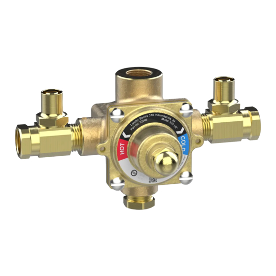
Model 310
Thermostatic Mixing Valve
CAPACITIES – MODEL 310
Pressure Drop PSI
5
Valve Number
310-1/2" GPM
1.5
310-1/2" LPM
5.7
310-3/4" GPM
3.5
310-3/4" LPM
13.3
A
72046_310-50_STD_DRW_NODIMS.pdf
DIMENSIONS
Valve Number
A
310
7"
Dimensions are for reference purposes only. For rough-in dimensions
please refer to Lawler's Revit/BIM models found at temperedwater.com.
Inlets are 1/2" NPT, outlet may be 1/2" or 3/4" NPT.
temperedwater.com
5330 East 25 th St.
Indianapolis, IN 46218
Phone (317) 261-1212
Fax (317) 261-1208
10
20
30
Capacity
2.5
3.5
5.5
9.5
13.3
20.8
26.5
5.5
8
10
20.8
30
38
C
B
B
C
4"
5"
temperedwater.com/patents
M 310 C
45
7
12
45
Advertisement

Subscribe to Our Youtube Channel
Related Manuals for Lawler 310


Summary of Contents for Lawler 310
- Page 1 7” 4” 5” Dimensions are for reference purposes only. For rough-in dimensions please refer to Lawler’s Revit/BIM models found at temperedwater.com. Inlets are 1/2” NPT, outlet may be 1/2” or 3/4” NPT. temperedwater.com/patents ASSE 1070 Approved Design and specifications subject to change without notice.
- Page 2 Maintenance CAUTION: Extreme care should be exercised when The Lawler thermostatic mixer should be checked placing thermostat in and out of hot water. periodically for proper operation and cleaning. See “INSPECTION AND CLEANING VALVE.” To test mixing...
- Page 3 Checking Piston and Liner Thermostatic Mixing Valve Cut-away Remove piston assembly #15 from valve. Check the piston assembly and liner #21 for cleanliness and excessive wear. Check hot disc #17 for wear. Replace all worn parts. Liner #21 can be removed with a 3/8” hex wrench for med & high flow 1/2”...
- Page 4 GUARANTEE We guarantee the Lawler Mixing Valve to be free from def ects in workmanship and material, and for a period of one year from date of purchase, will replace any parts found by us to be defective. We will not be held responsible, however, for any labor incidental to, or for any damages caused by defective material.
Need help?
Do you have a question about the 310 and is the answer not in the manual?
Questions and answers