Advertisement
Quick Links
5330 East 25 th Street
Indianapolis, Indiana 46218
Phone (317) 261-1212
Fax (317) 261-1208
www.temperedwater.com
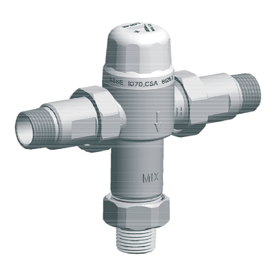
CSA B 125.3 Approved
ASSE 1070 Approved
ASSE 1069 Approved
California Proposition 65 Warning
Warning: product contains chemicals known to the State of California
to cause cancer and birth defects or other reproductive harm.
(Installer: California law requires that this warning be given to
the consumer)
VALVE SPECIFICATIONS
Outlet temperature range:
Temperature, hot supply:
Temperature, cold supply:
Temperature stability(nominal):
Temperature differential:
(between hot supply and outlet temperature)
Hydrostatic pressure:
Permitted supply pressure variation:
Flow rate @ 45psi pressure loss: 1/2"-
Flow rate,minimum:
Flow rate,maximum:
Notes:
1. As tested in accordance with ASSE 1070.
2. This is the minimum difference required between the valve outlet
temperature and the hot supply temperature to ensure shut-off of outlet
flow in the event of cold supply failure, in accordance with ASSE 1070.
3.Maximum permitted variation in either supply pressure in order to
control the outlet temperature to with ±5°F .Excessive changes in supply
pressure may cause changes in outlet temperature, that exceed ±5°F.
Installation
Manual
MODEL 570
Thermostatic Mixing
Valve
R
95~115°F(35~46°)
180°F max(82°)
40~80°F(4~27°)
±5°F(±2.8°)- See Note 1.
1/2"-
±10°F(±5.5°)-See Note 2 .
3/4"-
±10°F(±5.5° )-See Note 2 .
125psi max(1000kPa)
±20%-See Note 3.
9gpm (66L/min)
3/4"-
11gpm
0.5gpm(2L/min)
1/2"-
10gpm @ 60psi pressure lost
3/4"-
12gpm @ 60psi pressure lost
IMPORTANT
Failure to comply with all aspects of these instructions may result in
unsafe performance.
All installations must comply with relevant state and local authority
requirements.
Flush the system thoroughly before fitting the valve:
It is CRITICAL that all debris is flushed from the pipework prior to
installing the valve. Not flushing the system properly is the most
common cause of system difficulties.
Commission the valve:
Every valve is factory-set to a nominal temperature of 105°F. Every
must be adjusted on-site to ensure correct delivery of the
desired mixed water temperature , as installation conditions can vary
from site to site.
Check:
• Measure and note all site parameters (pressure , temperature, etc.)
and check against the specifications of the chosen valve. If the site
conditions are outside those specified for the valve then they must
be rectified prior to installing the valve.
• Valve MUST NOT be subjected to heat during installation as this
may damage the valve internals.
• Valve MUST NOT be fitted on steam-supplied systems, but to
water systems only.
• Valve MUST NOT be used on low pressure or instantaneous
heating systems.
• Valve MUST NOT be frozen. If the valve is installed in a situation
where freezing is a possibility, then suitable insulation must be
fitted to prevent damage to the valve.
• DO NOT use excess thread sealant (in liquid, tape or other form)
as this may cause the valve to fail.
Leave a copy of these instructions with the client for future reference.
Recommend to the client that the valve be checked annually to ensure
its continued function.
Cold Inlet
B
Tempered Outlet
A
DIMENSIONS
1 2 / "
5 7 143 5
. "(
. )
3/4"
5 7 143 5
. "(
. )
Dirgram 1
60
50
40
30
20
10
0
0
5
Flow Rate, Gal/Min
Dirgram 2
-
Flow Characteristics
A
Adjusting Dial
Hot Inlet
C
B
C
4 8 121
3 7 95
. "(
)
. "(
4 8 121
3 7 95
. "(
)
. "(
-
Valve Dimensions
Flow Curve
10
15
)
)
20
Advertisement

Subscribe to Our Youtube Channel
Related Manuals for Lawler 570


Summary of Contents for Lawler 570
- Page 1 Manual • Valve MUST NOT be frozen. If the valve is installed in a situation where freezing is a possibility, then suitable insulation must be MODEL 570 fitted to prevent damage to the valve. CSA B 125.3 Approved • DO NOT use excess thread sealant (in liquid, tape or other form) Thermostatic Mixing as this may cause the valve to fail.
- Page 2 Troubleshooting Guide Fitting the Valve • The mixed water outlet from the valve should be used to supply FAULT/SYMPTOM CAUSE SOLUTION outlets used primarily for personal hygiene purposes. • It is recommended that the valve is installed as close as possible 1.
Need help?
Do you have a question about the 570 and is the answer not in the manual?
Questions and answers