Table of Contents
Advertisement
Quick Links
Advertisement
Table of Contents

Related Manuals for Cisco MDS 9148V-K9


Summary of Contents for Cisco MDS 9148V-K9
- Page 1 Cisco MDS 9148V-K9 Switch Hardware Installation Guide First Published: 2022-07-19 Americas Headquarters Cisco Systems, Inc. 170 West Tasman Drive San Jose, CA 95134-1706 http://www.cisco.com Tel: 408 526-4000 800 553-NETS (6387) Fax: 408 527-0883...
- Page 2 RFP documentation, or language that is used by a referenced third-party product. Cisco and the Cisco logo are trademarks or registered trademarks of Cisco and/or its affiliates in the U.S. and other countries. To view a list of Cisco trademarks, go to this URL: http://www.cisco.com/go/trademarks.
-
Page 3: Table Of Contents
Reference Perforated Cabinet Requirements Specific to Solid-Walled Cabinets C H A P T E R 4 Installing the Cisco MDS 9148V-K9 Switch Preinstallation Cisco MDS 9000 Series Telco and EIA Shelf Bracket Shelf-Installation Guidelines Cisco MDS 9148V-K9 Switch Hardware Installation Guide... - Page 4 Removing and Installing Cables into SFP Transceivers Installing a Cable into an SFP Transceiver Removing a Cable from an SFP Transceiver Removing and Installing SFP Transceivers Installing an SFP Transceiver Removing an SFP Transceiver Cisco MDS 9148V-K9 Switch Hardware Installation Guide...
- Page 5 Connecting the Console Port to a Computer Using the DB-25 Adapter Connecting the Console Port to a Computer Using the DB-9 Adapter Out of Band Ethernet Management Port Supported Power Cords and Plugs Standard Power Cords Jumper Power Cords Fibre Cable Specifications Cisco MDS 9148V-K9 Switch Hardware Installation Guide...
- Page 6 Contents Cisco MDS 9148V-K9 Switch Hardware Installation Guide...
-
Page 7: Preface
C H A P T E R Preface This preface describes the audience, organization of, and conventions used in the Cisco MDS 9000 Series Configuration Guides. It also provides information on how to obtain related documentation, and contains the following chapters: •... -
Page 8: Related Documentation
To find a document online, use the Cisco MDS NX-OS Documentation Locator at: http://www.cisco.com/c/en/us/td/docs/storage/san_switches/mds9000/roadmaps/doclocater.html Obtaining Documentation and Submitting a Service Request For information on obtaining documentation, using the Cisco Bug Search Tool (BST), submitting a service request, and gathering additional information, see What's New in Cisco Product Documentation. - Page 9 Preface Obtaining Documentation and Submitting a Service Request To receive new and revised Cisco technical content directly to your desktop, you can subscribe to the What's New in Cisco Product Documentation RSS feed. RSS feeds are a free service. Cisco MDS 9148V-K9 Switch Hardware Installation Guide...
- Page 10 Preface Obtaining Documentation and Submitting a Service Request Cisco MDS 9148V-K9 Switch Hardware Installation Guide...
-
Page 11: Overview Of Cisco Mds 9148V-K9 Switch
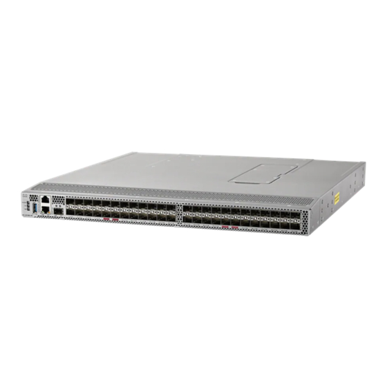
C H A P T E R Overview of Cisco MDS 9148V-K9 Switch The Cisco MDS 9148V-K9 switch has 48 x 8/16/32/64-Gbps multispeed ports and is a powerful and compact 1-rack unit (1 RU) SAN fabric switch. This switch has the following major features: •... -
Page 12: Front View
Fixed FC ports (48 x 8/16/32/64 Gbps, and (33-36) pluggable SFP or SFP+ compatible) Fibre Channel port groups. A port FC port status LEDs (48) group consists of 24 ports. Airflow grill Management port packet activity LEDs (2) Cisco MDS 9148V-K9 Switch Hardware Installation Guide... -
Page 13: Rear View
Power supply unit latch release (1 per PSU) Unswitched power socket (IEC C14, Power supply units (2) 1 per PSU) Chassis fan module release latches (2 Power supply status LED (1 per PSU) per fan module) Cisco MDS 9148V-K9 Switch Hardware Installation Guide... -
Page 14: Leds
Overview of Cisco MDS 9148V-K9 Switch LEDs Figure 3: Rear Panel Slot Numbering of Cisco MDS 9148T Power supply unit slot 1 Chassis fan module slot 3 Chassis fan module slot 1 Chassis fan module slot 4 Chassis fan module slot 2... - Page 15 No input to the PSU. Voltage Green Status Solid on PSU output is OK. PSU Voltage Status LED Blinking PSU output is not OK, but input is OK. (faceplate of each PSU) Cisco MDS 9148V-K9 Switch Hardware Installation Guide...
- Page 16 The link is up and the port beacon is active. Intermittent Blinking Green The link is up and traffic is flowing through the port. Solid Orange The link is disabled by the software. Blinking Orange A fault condition exists. No link. Cisco MDS 9148V-K9 Switch Hardware Installation Guide...
-
Page 17: Fan Modules
PSU replacement, the internal airflow through the chassis is changed. If the internal airflow is disrupted for too long, the preset temperature thresholds will be exceeded and the system will automatically shut down to prevent permanent damage. Cisco MDS 9148V-K9 Switch Hardware Installation Guide... - Page 18 PSUs. Note The direction of PSU airflow must match the direction of the fan module airflow. For more information on installing and removing PSUs, see Installing and Removing Power Supply Units. Cisco MDS 9148V-K9 Switch Hardware Installation Guide...
-
Page 19: Cabinet And Rack Installation
Cabinet and Rack Requirements This section provides the Cisco MDS 9000 Series switches requirements for the following types of cabinets and racks in an external ambient air temperature range of 0 to 40°C. If you are selecting an enclosed cabinet, we recommend that you choose one of these thermally validated types: •... -
Page 20: Requirements Specific To Perforated Cabinets
• The distance between the outside face of the front mounting post and the outside face of the back mounting post should be 26 to 32 in. (66 to 81 cm) to allow for installation with the Cisco rack mounting kit. - Page 21 • A minimum of 150 sq. in. (968 sq. cm) of open area to be available at the floor air intake of the cabinet. • The lowest piece of equipment to be installed at a minimum of 1 RU (1.75 in. or 4.4 cm) above the floor openings to prevent blockage of the floor intake. Cisco MDS 9148V-K9 Switch Hardware Installation Guide...
- Page 22 Cabinet and Rack Installation Requirements Specific to Solid-Walled Cabinets Cisco MDS 9148V-K9 Switch Hardware Installation Guide...
-
Page 23: Installing The Cisco Mds 9148V-K9 Switch
C H A P T E R Installing the Cisco MDS 9148V-K9 Switch This chapter describes how to install a Cisco MDS 9148V-K9 switch and its components. Before you install, operate, or service the system, see the Regulatory Compliance and Safety Information for the Cisco MDS 9000 Family document for important safety information. -
Page 24: Shelf-Installation Guidelines
• Tape measure and level (to ensure that shelf brackets are at level with each other) Installing the Shelf Bracket Kit into a Four-Post EIA Rack The following figure shows the installation of the shelf bracket kit into a four-post EIA rack: Cisco MDS 9148V-K9 Switch Hardware Installation Guide... - Page 25 Insert the slider posts into the shelf brackets, as shown in Installing the Shelf Bracket Kit into an EIA Rack. Attach them to the rear rack-mounting posts, using a minimum of four 12-24 or 10-24 screws. Cisco MDS 9148V-K9 Switch Hardware Installation Guide...
-
Page 26: Preinstallation Guidelines
• Ensure that the site power meets the power requirements listed in the Technical Specifications section. If available, you can use an uninterruptible power supply (UPS) to protect against power failures. Cisco MDS 9148V-K9 Switch Hardware Installation Guide... -
Page 27: Unpacking And Inspecting The Switch
The switch is thoroughly inspected before shipment. If any damage occurs during transportation, or if any item is missing, contact your customer representative immediately. If you purchased Cisco support through a Cisco reseller, contact the reseller directly. If you purchased support directly from Cisco, contact Cisco Technical Support. -
Page 28: Nebs Compliance
2. Install the NEBS air baffle by aligning the notches on the baffle with the slots on the brackets and sliding the ends of the baffle so that the baffle locks into place. Figure 7: NEBS Kit for 2-Post Installation Cisco MDS 9148V-K9 Switch Hardware Installation Guide... -
Page 29: Installing The Switch
Typically, the front of the rack is the side that is easiest to access for maintenance. Before you begin • Inspect the switch shipment to ensure that you have everything you ordered. • Make sure that the switch rack-mount kit includes the following parts: Cisco MDS 9148V-K9 Switch Hardware Installation Guide... - Page 30 If the rear end of the chassis is to be inserted first, then mount the brackets on the front of the chassis, and vice versa. Cisco MDS 9148V-K9 Switch Hardware Installation Guide...
- Page 31 To make sure that the slider rails are at the same level, you should use a level tool or tape measure, or carefully count the screw holes in the vertical mounting posts. Step 4 Insert the switch into the rack and attach it as follows: Cisco MDS 9148V-K9 Switch Hardware Installation Guide...
- Page 32 Tighten the 10-32 screws to 20 in-lb (2.26 N·m), or tighten the 12-24 screws to 30 in-lb (3.39 N·m). Step 5 If you have attached a grounding wire to the chassis grounding pad, connect the other end of the wire to the facility ground. Cisco MDS 9148V-K9 Switch Hardware Installation Guide...
-
Page 33: Installing The Switch Into A 2-Post Rack
If the rear end of the chassis is to be inserted first, then mount the brackets on the front of the chassis, and vice versa. Cisco MDS 9148V-K9 Switch Hardware Installation Guide... - Page 34 Holding the chassis level, insert three screws (12-24 or 10-32, depending on the rack type) into each of the two rack-mount brackets (using a total of six screws) and into the cage nuts or threaded holes in the rack or cabinet posts. Cisco MDS 9148V-K9 Switch Hardware Installation Guide...
- Page 35 Figure 12: Installing the Switch onto the 2-Post Rack From the Rear Side of the Chassis c. Tighten the 10-32 screws to 20 in-lb (2.26 N.m) or tighten the 12-24 screws to 30 in-lb (3.39 N.m). Cisco MDS 9148V-K9 Switch Hardware Installation Guide...
-
Page 36: Grounding The Switch
M4 screws, and tighten each screw to 11.5 to 15 in-lb (1.3 to 1.7 N·m) of torque. Figure 13: Grounding the Switch Chassis grounding pad Two M4 screws are used to secure the grounding lug to the chassis Cisco MDS 9148V-K9 Switch Hardware Installation Guide... -
Page 37: Installing And Removing Components
The figures show how to cuff the ESD strap around the wrist and the ground cord that connects the cuff to the ground. ESD wrist straps are the primary means of controlling static charge on personnel. Cisco MDS 9148V-K9 Switch Hardware Installation Guide... - Page 38 Installing the Cisco MDS 9148V-K9 Switch Installing the ESD Grounding Strap Note These images are for only representation purposes. The chassis' actual appearance and size may vary. Figure 14: Wearing the ESD Strap Cisco MDS 9148V-K9 Switch Hardware Installation Guide...
-
Page 39: Installing And Removing Power Supply Units
You can replace one power supply unit (PSU) while the other one provides power to the switch. Before you begin • To implement n+n redundancy, each PSU must be connected to a separate power feed. Otherwise, only one power feed is required. Cisco MDS 9148V-K9 Switch Hardware Installation Guide... -
Page 40: Removing Power Supply Units
If you cannot perform the replacement within one minute, leave the original fan module in the chassis to maintain the designed airflow until you have the replacement fan module on hand and can perform the replacement. Cisco MDS 9148V-K9 Switch Hardware Installation Guide... -
Page 41: Installing A Fan Module
Caution The Cisco MDS 9000 Series Switches have internal temperature sensors that can shut down the system if the temperature within the chassis exceed certain safety thresholds. To accurately monitor the system temperature, the temperature sensors require sufficient airflow through the chassis. In the event that a fan module is removed from the chassis and the airflow is reduced, the system will bypass the temperature sensor information and shut down after five minutes to prevent undetected overheating. - Page 42 Holding the handle, pull the module out of the chassis. Caution Do not touch the electrical connectors on the back side of the module and prevent anything else from coming into contact with and damaging the connectors. Cisco MDS 9148V-K9 Switch Hardware Installation Guide...
-
Page 43: Connecting The Cisco Mds 9148V-K9 Switch
• USB port—USB port for USB disk that you can use for configuration file backups, and capturing logs to file. This chapter describes how to connect the various components of the Cisco MDS 9148V-K9 switch. • Preparing for Network Connections, on page 37 •... -
Page 44: Connecting The Console Port
Step 3 Connect one end of the supplied console cable (a rollover RJ-45-to-RJ-45 cable) to the console port. Connect the other end to the female RJ-45 adapter attached to the PC communication port. Cisco MDS 9148V-K9 Switch Hardware Installation Guide... -
Page 45: Connecting A Modem To A Console Port
(labeled MGMT ETH0 and MGMT ETH1), below the console port. MGMT ETH0 is the default Ethernet management port (interface mgmt0). This port is used for out-of-band management and data streaming to remote receivers. Cisco MDS 9148V-K9 Switch Hardware Installation Guide... -
Page 46: Connecting To A Fibre Channel Port
Installing a Cable into an SFP Transceiver Caution To prevent possible damage to the cable or transceiver, install the transceiver in the port before installing the cable in the transceiver. Cisco MDS 9148V-K9 Switch Hardware Installation Guide... -
Page 47: Removing A Cable From An Sfp Transceiver
Press the release latch on the cable, grasp the connector near the connection point, and gently pull the connector from the transceiver. Step 3 Insert a dust plug into the cable-end of the transceiver. Cisco MDS 9148V-K9 Switch Hardware Installation Guide... -
Page 48: Removing And Installing Sfp Transceivers
SFP transceivers to prevent damage to the cable or transceiver. Note Use only Cisco transceivers in this switch. Each Cisco transceiver is encoded with model information that enables the switch to verify that the transceiver meets the requirements for the switch. -
Page 49: Maintaining Sfp Transceivers And Fiber-Optic Cables
This switch is designed to boot up in less than 30 minutes. This is dependent on all associated devices, already running and fully operational. To power up the switch and verify hardware operation, follow these steps: Cisco MDS 9148V-K9 Switch Hardware Installation Guide... - Page 50 Do not operate the switch without a functioning fan module, except briefly during the fan module replacement procedure. Cisco MDS 9000 Series Switches can operate for only a few minutes without any functioning fan modules before they begin to overheat.
-
Page 51: Technical Specifications
Chassis requires 1 RU (1.75 in. or 4.45 cm) Weight 21.8 lb (9.9 kg) unpopulated Fan Dimensions (WxH) 1.575 x 1.575 in. (4.0 x 4.0 cm) Fan Slots Opening Dimensions (WxH) 1.614 x 1.602 in. (4.09 x 4.06 cm) Cisco MDS 9148V-K9 Switch Hardware Installation Guide... -
Page 52: Power Specifications
Table 4: Power Supply Specifications AC Input Power Specification AC input voltage 100 to 240 VAC AC input frequency Nominal = 50 to 60 Hz Power supply output capacity 500 W Output holdup time 20 ms Cisco MDS 9148V-K9 Switch Hardware Installation Guide... -
Page 53: Power Supply Requirement Specifications
• The environment (temperature) outside the chassis • Internal chassis temperature • Any hardware component failure in the chassis • Average switching traffic levels Cisco MDS 9148V-K9 Switch Hardware Installation Guide... - Page 54 Table 7: Power Requirements (maximum) and Heat Dissipation for the Switch Module Power Required Heat Dissipation Input Current Type/Product (Watts) (BTU/hr) 110 VAC (Amps) 220 VAC (Amps) Number Cisco MDS 314 (Max) 2.94 1.42 9148V-K9 64-Gbps 48-port Switch Cisco MDS 9148V-K9 Switch Hardware Installation Guide...
-
Page 55: Appendix A Cable And Port Specifications
Additional cables and adapters can be ordered from your customer service representative. Note If you purchased this product through a Cisco reseller, contact the reseller directly for technical support. If you purchased this product directly from Cisco, contact Cisco Technical Support at http://www.cisco.com/c/en/us/support/index.html. -
Page 56: Console Port
RJ-45-to-RJ-45 rollover cable, and the RJ-45-to-DB-25 female DTE adapter: Table 9: Port-Mode Signaling and Pinouts with DB-25 Adapter Console Port RJ-45-to-RJ-45 Rollover Cable RJ-45-to-DB-25 Console Device Terminal Adapter Signal RJ-45 Pin RJ-45 Pin DB-25 Pin Signal Cisco MDS 9148V-K9 Switch Hardware Installation Guide... -
Page 57: Connecting The Console Port To A Computer Using The Db-9 Adapter
Signal RJ-45 Pin RJ-45 Pin DB-9 Pin Signal Out of Band Ethernet Management Port Use a modular, RJ-45, straight-through UTP cable to connect the 10/100/1000 management Ethernet port to external hubs and switches. Cisco MDS 9148V-K9 Switch Hardware Installation Guide... - Page 58 The following figure shows a schematic representation of the 10/100/1000 BASE-T cable: Figure 18: Twisted-Pair 10/100/1000 BASE-T Cable The following table lists the connector pinouts and signal names for a 10/100 BASE-T management port (MDI) cable: Cisco MDS 9148V-K9 Switch Hardware Installation Guide...
-
Page 59: Supported Power Cords And Plugs
Supported Power Cords and Plugs Each switch power supply unit requires one power cord. Cisco approved cords may be ordered with the product. Standard power cords with a country specific plug can be used with wall outlets. Jumper power cords can be used with cabinet outlets. -
Page 60: Standard Power Cords
Standard Power Cords Cisco standard power cords for the switch have an IEC C15 connector on the outlet end of the cord and a country specific plug on the inlet end of the cord. The following table lists the supported power cords and power plugs for the switch:... -
Page 61: Jumper Power Cords
The following table lists the supported jumper power cords and power plugs for the switch. Table 14: Supported Jumper Power Cords Description Plug Type Length Illustration CAB-C13-C14-2M IEC C14 (250 VAC 10 6.6 ft (2.0 m) Cisco MDS 9148V-K9 Switch Hardware Installation Guide... -
Page 62: Fibre Cable Specifications
Plug Type Length Illustration CAB-C13-C14-3M IEC C14 (250 VAC 10 9.8 ft (3.0 m) Fibre Cable Specifications For information on the fibre cable specifications, see the Cisco MDS 9000 Family Pluggable Transceivers Data Sheet. Cisco MDS 9148V-K9 Switch Hardware Installation Guide...
Need help?
Do you have a question about the MDS 9148V-K9 and is the answer not in the manual?
Questions and answers