Table of Contents
Advertisement
Quick Links
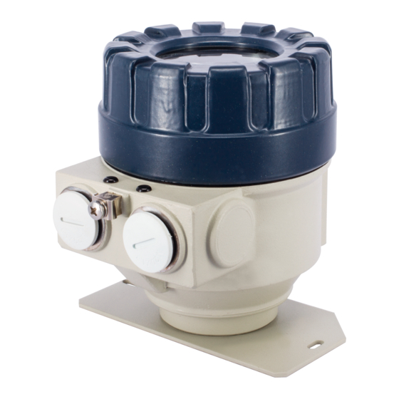
PDF – loop indicator and
converter to HART
INSTALLATION AND PROGRAMMING MANUAL
3
Edition
rd
Manufacturer:
NIVELCO Process Control Co.
1043 Budapest, Dugonics u. 11.
Tel: (36-1) 889-0100 ♦ Fax: (36-1) 889-0200
e-mail: sales@nivelco.com ♦ www.nivelco.com
♦
♦
BKI 04 ATEX 121X
pdf4012a0600p_03.doc
1 / 24
Advertisement
Table of Contents

Related Manuals for NIVELCO UNICONT PDF 01-2 Series


Summary of Contents for NIVELCO UNICONT PDF 01-2 Series
- Page 1 PDF – loop indicator and converter to HART INSTALLATION AND PROGRAMMING MANUAL Edition Manufacturer: NIVELCO Process Control Co. 1043 Budapest, Dugonics u. 11. Tel: (36-1) 889-0100 ♦ Fax: (36-1) 889-0200 e-mail: sales@nivelco.com ♦ www.nivelco.com ♦ ♦ BKI 04 ATEX 121X pdf4012a0600p_03.doc...
- Page 2 ♦ ♦ 2 / 24 pdf4012a0600p_03.doc BKI 04 ATEX 121X...
-
Page 3: Table Of Contents
C O N T E N T S 1. INTRODUCTION ......................................5 2. ORDER CODES......................................5 3. TECHNICAL DATA....................................... 6 3.1 G ......................................6 ENERAL DATA 3.2 D ......................................7 IMENSIONS 3.3 A ......................................8 CCESSORIES 4. INSTALLATION AND ELECTRIC CONNECTION ............................9 4.1 W ........................................ - Page 4 ♦ ♦ 4 / 24 pdf4012a0600p_03.doc BKI 04 ATEX 121X...
-
Page 5: Introduction
Thank you for choosing NIVELCO instrument We are sure that you will be satisfied throughout its use! 1. INTRODUCTION The UNICONT PDF-4/501 and PDF-401-6/A/C Ex devices are 2-wire on-site indicators that can be inserted into a 4 … 20 mA current loop without the need for additional power supply. -
Page 6: Technical Data
3. TECHNICAL DATA 3.1 G ENERAL DATA PDF- 01-2 P F- 01-4 PDF-401-6 E P F-401-8 E PDF-401-A E P F-401-B E PDF-401-C E P F-401-D E Powering 2-wire 3-wire Input Current loop Range 3.6 … 22 mA 0 … 22 mA Display/indication 6-digit LCD, engineering units and bargraph Range of displayed value... -
Page 7: Imensions
DDITIONAL DATA FOR X CERTIFIED VERSIONS PDF – 401 – 6 E PDF – 401 – A E PDF – 401 – C E Ex protection Intrinsically safe Flame proof Flame proof, intrinsically safe Ex marking II 1 G EEx ia IIC T6 II 2 G EEx d IIB T6 II 1/2 G EEx d ia IIB T6 = 2,1 V I... -
Page 8: Accessories
3.3 A CCESSORIES Ordinary, EEx ia: EEx d, EEx d ia: HART capable units – Installation and programming manual – Installation and programming manual - EView Light software on CD-ROM (in addition) – Warranty Card – Warranty Card – Declaration of Conformity –... -
Page 9: Installation And Electric Connection
4. INSTALLATION AND ELECTRIC CONNECTION The devices are suitable for working in closed areas or they can be used in open-air applications, too. Installation location should be selected so that proper space is available for handling, programming and checking the display. Mounting the units on the wall or to a support can be done with using 2pcs of M4 nuts. 4.1 W IRING •... - Page 10 P F - 01-4 4-20mA HART 0-20mA Transmitter ≥ Ω Figure 4. Wiring of a HART capable (3-wire) Unicont in the current loop of a 4-wire transmitter. P F- 01-8/B/D Ex Multicont Transmitter Ex Ω HART R = 250 4-20mA P F- 01-8/B/D Ex Transmitter Ex 4-20mA...
- Page 11 P F- 01-4 4-20mA 0-20mA Multicont Transmitter HART Ω R = 250 P F- 01-4 4-20mA 0-20mA Transmitter Wiring of -wire Figure 6. Uniconts with Multicont controller and 4-wire transmitters R=10 Figure 7. Internal wiring of the 2-wire Unicont Figure 8. Internal wiring the of 3-wire Unicont ♦...
-
Page 12: Safety Regulations For The Ee X Certified Units
4.2 S AFETY REGULATIONS FOR THE ERTIFIED UNITS Intrinsically safe units with EEx ia IIC, EEx ia IIB or EEx d ia IIB markings can only be used in duly certified intrinsically safe loops with the previously given technical data. Devices should be grounded by connecting their grounding screws to the equipotential system. -
Page 13: Default
5.1 D EFAULT Manufacturer’s settings are the following: The percental (%) value shown on the display is proportional to the input (4 mA→ 0%, 20 mA →100.0%). Damping: 3 s Noise suppression frequency: 50 Hz Programming Programming keys keys Bargraph indication is proportional to the input ( 0/4 mA→ 0%, 20 mA →100.0%). The output of the 3-wire models can be 4…20 mA current and / or HART signal During operation: COM LED flashes during HART communication... -
Page 14: Display Of The Sap-202 And Keys Of The Unit
5.2 D SAP-202 ISPLAY OF THE AND KEYS OF THE UNIT Symbols on the screen Symbols and sign on the frame • • DIST – distance displayed (when ON) M – metric system • • LEV – level displayed (when ON) US –... -
Page 15: Steps Of Programming
5.3.1. S TEPS OF PROGRAMMING ‘Double key pressing’ (pressing two keys simultaneously) has to be used to get into and out of PROGRAMMING mode. It is also used in programming mode. This is represented in the manual with the symbols of the two keys and the ‘+’ sign in between them. That is: (getting into PROGRAMMING mode). - Page 16 OPERATION OF THE PROGRAMMING KEYS RESSING KEY OPERATION Getting in and out of PROGRAMMING and MEASUREMENT mode (both directions). (Returning to Measurement mode means saving of the modifications) (press for minimum 3 sec) In MEASUREMENT mode input or output current appears on the screen of the 2-wire or 3-wire model respectively while Parameter address blinking while Parameter value blinking to select parameter address and go to parameter value...
-
Page 17: Parameters - Description And Programming
5.3.2. P – ARAMETERS DESCRIPTION AND PROGRAMMING Attention! Before programming it is suggested to read the description of parameter P10 carefully! - - - a Setting input current (Ia) that is to be assigned to displayed value (Da) See Figure 9, 10 and 11 FACTORY DEFAULT: 4 mA - - - a Setting input current (Ib) to be assigned to displayed value (Db) - Page 18 Displayed Displayed value value 29999 29999 Iin (mA) Iin (mA) Input Input current current -9999 -9999 Figure 9. Display curve of 2-wire models Figure10. Display curve of 3-wire models with input range set for 4…20 mA Displayed value 29999 Iin (mA) Input current -9999...
- Page 19 - - - a Current generator test (for 3-wire models only) In this parameter the actual current output is displayed. Going to the parameter value the output current of 3.6…22 mA can be set by the keys urrent value entered this way should conform with the output current measured with an ammeter. .
- Page 20 P11: dcba Setting range,* damping, noise suppression, error indication on the output current * FACTORY DEFAULT: 0000 Range can be selected with the 3-wire models for 4…20 mA or 0…20 mA . Setting is important in respect to the output current error indication.
- Page 21 P12: dcba Displayed process values and their units FACTORY DEFAULT: 0100 The columns of the chart below can be programmed separately and it is supposed to be done reasonably (i.e. to have symbol LEV lit: 2 should be set under b, to have relevant unit lit (m/ft or cm/in) 2 or 3 should be set under a and setting 1 under d should be chosen if the required unit is meter or centimetre.
- Page 22 STon/yd gal/s kg/min ft/h Mgal/d kg/h kg/d HJ/h ML/d MetTon/min in/s ft/s Codes over 240 are engineering units defined by NIVELCO They might be different at other manufacturers. ♦ ♦ 22 / 24 pdf4012a0600p_03.doc BKI 04 ATEX 121X...
-
Page 23: Error Indications
P19: Secret code FACTORY DEFAULT: 0000 Settings can be protected by a 4 digit number (secret code) (other than 0000) entered in this parameter. If the secret code is active the PROG symbol is lit and the value of the parameters can only be viewed. To be able to do any programming or to modify the secret code or to remove protection (modify the secret code to 0000) the secret code, already entered, needs to be known. -
Page 24: Maintenance And Repair
The unit does not require regular maintenance. In case of need the unit might be carefully cleaned. All repairs will be carried out only on the premises of the Manufacturer. 7. STORAGE Ambient temperature: –25 °C ... +60 °C Relative humidity: max. 98 % pdf4012a0600p_03.doc NIVELCO Process Control Co. May 2006. reserves the right to change technical specifications without notice. NIVELCO ♦ ♦ 24 / 24 pdf4012a0600p_03.doc...
Need help?
Do you have a question about the UNICONT PDF 01-2 Series and is the answer not in the manual?
Questions and answers