HWH 310 Series Operator's Manual
Hide thumbs
Also See for 310 Series:
- Operator's manual (25 pages) ,
- Operator's manual (8 pages) ,
- Operator's manual (20 pages)
Table of Contents
Advertisement
Quick Links
OPERATOR'S MANUAL
HWH TOUCH PANEL-CONTROLLED
STRAIGHT-ACTING FRONT JACKS
AP10045 - US
AP10272 - Europe
AP21562 - French
H
W
CORPORATION
LEVELING SYSTEM
310 SERIES FIFTH WHEEL
FEATURING:
TOUCH PANEL CONTROL
HYDRAULIC LEVELING
FRONT JACK EQUALIZATION
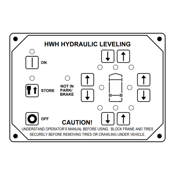
HWH HYDRAULIC LEVELING
ON
STORE
OFF
CAUTION!
UNDERSTAND OPERATOR'S MANUAL BEFORE USING. BLOCK FRAME AND TIRES
SECURELY BEFORE REMOVING TIRES OR CRAWLING UNDER VEHICLE.
HWH CORPORATION
(ON I-80, EXIT 267 SOUTH)
2096 MOSCOW ROAD
MOSCOW, IOWA 52760
(800) 321-3494 / (563) 724-3396
INTERNET: http: //www.hwhcorp.com
H
R
ML10045/MP05.3013/TH-FW
18MAY01
Advertisement
Table of Contents

Subscribe to Our Youtube Channel
Related Manuals for HWH 310 Series


Summary of Contents for HWH 310 Series
- Page 1 CORPORATION OPERATOR’S MANUAL HWH TOUCH PANEL-CONTROLLED LEVELING SYSTEM 310 SERIES FIFTH WHEEL FEATURING: TOUCH PANEL CONTROL HYDRAULIC LEVELING STRAIGHT-ACTING FRONT JACKS FRONT JACK EQUALIZATION HWH HYDRAULIC LEVELING STORE CAUTION! UNDERSTAND OPERATOR’S MANUAL BEFORE USING. BLOCK FRAME AND TIRES SECURELY BEFORE REMOVING TIRES OR CRAWLING UNDER VEHICLE.
-
Page 2: How To Obtain Warranty Service
HWH CORPORATION personnel will contact you to the problem quickly. If the dealer has difficulty solving determine whether or not your claim is valid. If it is, HWH the problem, he should immediately contact the Customer CORPORATION will authorize repair or replacement of the Service Department, at HWH CORPORATION. -
Page 3: Control Identification
CONTROL IDENTIFICATION RETRACT FRONT BUTTON EXTEND FRONT BUTTON WARNING LIGHTS ON LIGHT HWH HYDRAULIC LEVELING (4 - Red) "ON" BUTTON STORE LIGHT EXTEND RIGHT SIDE BUTTON STORE RETRACT RIGHT SIDE BUTTON "STORE" BUTTON LEVELING LIGHTS "OFF" BUTTON CAUTION! (4 - Yellow) UNDERSTAND OPERATOR’S MANUAL BEFORE USING. -
Page 4: Operating Procedures
1. Trailer must be unhitched from the tow vehicle before level- ing. The HWH front jacks may be used to lift the trailer for NOTE:The jack stop rods should be set anytime the trailer unhitching. - Page 5 OPERATING PROCEDURES STOP ROD RETAINING PIN STOP ROD POSITION PREPARATION FOR TRAVEL 1. Before retracting the jacks, the stop rods must be returned 4. Hitch the trailer to the tow vehicle using the procedure sup- to the travel position. plied by the trailer manufacturer. CAUTION: WHEN STORING THE JACK STOP RODS, 5.
- Page 6 OPERATING PROCEDURES MANUAL JACK RETRACTION IMPORTANT : Retract all room extensions before using the 4. Retract the rear jacks. valve release "T" handles. 5. Return the stop rods before retracting the front jacks. NOTE: Use the valve release "T" handles for retracting only if the "STORE"...
-
Page 7: Maintenance
All major components of the system can be replaced become caked or clogged with mud. This condition may with rebuilt units or can be sent to HWH CORPORATION to hamper the proper operation of the leveling system. This be rebuilt, when the system is out of warranty. -
Page 8: System Adjustment
MAINTENANCE SYSTEM ADJUSTMENT LOWER UPPER SET SCREW, HORIZONTAL ADJUSTING ADJUSTING ADJUSTMENT ADJUSTING LOCK NUTS, STOP STANDARD & VERTICAL LOW PROFILE ADJUSTMENT UNITS 6,000 lb. JACK 9,000 lb. JACK JACK ADJUSTMENT There are two basic adjustments which are made at the time bolts;... - Page 9 TROUBLE SHOOTING LEVELING SYSTEM The following is a list of problems, and possible solutions, which might occur to the leveling system. · NOTE: Only qualified technicians should install or repair leveling systems on vehicles. A knowledge of hydraulics, welding, the vehicle’s suspension and electrical system, as well as an understanding of the leveling system’s hydraulics and electronics is required.
- Page 10 HYDRAULIC CONNECTION DIAGRAM 310 SERIES LEVELING SYSTEM WITH FRONT EQUALIZATION FIFTH WHEEL NOTE: VIEW IS SHOWN WITH LEVELING MANIFOLD ONLY, OTHER MANIFOLDS MAY BE ATTACHED. VALVE RELEASE "T" HANDLES PUMP/MANIFOLD ASSEMBLY NOTE: BEFORE OPERATING VALVE RELEASE "T" HANDLE, READ AND UNDERSTAND PROCEDURE FOR MANUAL JACK RETRACTION IN OPERATOR’S INSTRUCTIONS.
- Page 11 ELECTRICAL CONNECTION DIAGRAM 310 SERIES LEVELING SYSTEM FIFTH WHEEL #10 WIRE TO GROUND STUD - (WHITE) 6230 TOUCH +12 FROM FUSE 15AMP PANEL SEE CONTROL BOX MAX - (BROWN) 6100 ELECTRICAL CONNECTION DIAGRAM WIRE TO GROUND STUD ON BOX - (BLUE) 9000...
- Page 12 ELECTRICAL CONNECTION DIAGRAM 310 SERIES CONTROL BOX FIFTH WHEEL AND TRAVEL TRAILER LR - (BROWN) 4400 LOCK - (PURPLE) 1410 LF - (BLUE) 1400 RF - (GREEN) 2400 RR - (ORANGE) 3400 PRESSURE SWITCH - (BLACK) 8100 LOCK FUSE LR FUSE...
- Page 13 ELECTRICAL CONNECTION DIAGRAM 310 SERIES LEVELING SYSTEM HYDRAULIC MANIFOLD-PUMP RELAY FIFTH WHEEL AND TRAVEL TRAILER MANIFOLD DIAGRAM VALVE RELEASE SEE POWER UNIT/HARNESS 6233 "T" HANDLE GROUNDING INSTRUCTIONS RIGHT FRONT PRESSURE LOCK SOLENOID VALVE (RF) SWITCH NOTE: THE (4) DIGIT WIRE NUMBER SUPERSEDES ANY AND ALL WIRE COLORS.
- Page 14 POWER UNIT/HARNESS GROUNDING INSTRUCTIONS 310 SERIES LEVELING SYSTEM FIFTH WHEEL AND TRAVEL TRAILER WELDED PUMP MOUNT Use grounding stud and 3/8" internal star lockwashers as shown. IMPORTANT: STAR LOCKWASHER MUST BE USED BETWEEN GROUNDING SURFACE AND WIRE TERMINALS PUMP MTG.
Need help?
Do you have a question about the 310 Series and is the answer not in the manual?
Questions and answers