HWH 610 SERIES Operator's Manual
Computer-controlled leveling system.
featuring:
touch panel control
hydraulic leveling
automatic suspension air dump
straight-acting jacks
dual cylinder room extension
lateral arm room extension
dual cylinder generator slide
(with synchronizing cylind
Hide thumbs
Also See for 610 SERIES:
- Service manual (38 pages) ,
- Operator's manual (24 pages) ,
- Operator's manual (12 pages)
Table of Contents
Advertisement
Quick Links
OPERATOR'S MANUAL
HWH COMPUTER-CONTROLLED
AUTOMATIC SUSPENSION AIR DUMP
DUAL CYLINDER ROOM EXTENSION
LATERAL ARM ROOM EXTENSION
DUAL CYLINDER GENERATOR SLIDE
(WITH SYNCHRONIZING CYLINDER)
SINGLE CYLINDER GUIDED ROOM EXTENSION
AP24840
H
W
CORPORATION
LEVELING SYSTEM
610 SERIES
FEATURING:
TOUCH PANEL CONTROL
HYDRAULIC LEVELING
STRAIGHT-ACTING JACKS
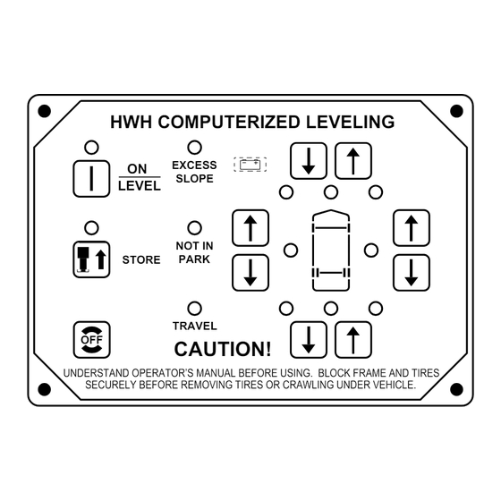
HWH COMPUTERIZED LEVELING
EXCESS
LEVEL
SLOPE
NOT IN
PARK/
BRAKE
STORE
DUMP
TRAVEL
OFF
CAUTION!
UNDERSTAND OPERATOR'S MANUAL BEFORE USING. BLOCK FRAME AND TIRES
SECURELY BEFORE REMOVING TIRES OR CRAWLING UNDER VEHICLE.
HWH CORPORATION
(ON I-80, EXIT 267 SOUTH)
2096 MOSCOW ROAD
MOSCOW, IOWA 52760
(800) 321-3494 / (563) 724-3396
INTERNET: http: //www.hwhcorp.com
H
R
ML24254/MP05.5220
25APR02
Advertisement
Table of Contents

Subscribe to Our Youtube Channel
Related Manuals for HWH 610 SERIES


Summary of Contents for HWH 610 SERIES
- Page 1 CORPORATION OPERATOR’S MANUAL HWH COMPUTER-CONTROLLED LEVELING SYSTEM 610 SERIES FEATURING: TOUCH PANEL CONTROL HYDRAULIC LEVELING AUTOMATIC SUSPENSION AIR DUMP STRAIGHT-ACTING JACKS DUAL CYLINDER ROOM EXTENSION LATERAL ARM ROOM EXTENSION DUAL CYLINDER GENERATOR SLIDE (WITH SYNCHRONIZING CYLINDER) SINGLE CYLINDER GUIDED ROOM EXTENSION...
- Page 2 HWH CORPORATION personnel will contact you to the problem quickly. If the dealer has difficulty solving determine whether or not your claim is valid. If it is, HWH the problem, he should immediately contact the Customer CORPORATION will authorize repair or replacement of the Service Department, at HWH CORPORATION.
- Page 3 CONTROL IDENTIFICATION "EXCESS SLOPE" LOW BATTERY LIGHT LIGHT FRONT RETRACT BUTTON "NOT IN PARK" LIGHT FRONT EXTEND BUTTON LEVEL LIGHT HWH COMPUTERIZED LEVELING "LEVEL" BUTTON WARNING LIGHTS (4- Red) EXCESS LEVEL SLOPE STORE LIGHT RIGHT SIDE EXTEND BUTTON NOT IN...
- Page 4 CONTROL IDENTIFICATION GENERATOR SLIDE ROOM EXTENSION MASTER SWITCH MASTER SWITCH EXTEND EXTEND ROOM ROOM SLIDE SLIDE SLIDE SLIDE RETRACT RETRACT GENERATOR SLIDE ROOM EXTENSION CONTROL SWITCH CONTROL SWITCH GENERATOR SLIDE MASTER SWITCH: ROOM EXTENSION MASTER SWITCH: THIS SWITCH MUST BE ON BEFORE THE THIS SWITCH MUST BE ON BEFORE THE GENERATOR SLIDE CAN BE EXTENDED OR ROOM CAN BE EXTENDED OR RETRACTED.
- Page 5 OPERATING PROCEDURES GENERAL INSTRUCTIONS If parking on soft ground or asphalt paving, wood blocks or If the "LOW BATTERY" indicator is on, the system should be pads must be placed under the jacks. checked. Battery voltage should be checked, also all connections should be checked.
- Page 6 OPERATING PROCEDURES AUTOMATIC HYDRAULIC LEVELING 1. Place transmission in the recommended position for park- extend any remaining jacks until they touch the ground. After ing vehicle and set parking brake. Turn the coach engine off. the system has finished leveling and stabilizing, and has com- Turn the ignition to the "ACCESSORY"...
- Page 7 NOTE: Make sure there is adequate clearance to fully room. DO NOT reverse direction of the room, contact extend the room. HWH Customer Service for assistance 1-800-321-3494. 3. Turn the ignition switch to "ACCESSORY". NOTE: Releasing the CONTROL SWITCH will halt the operation of the room.
- Page 8 DO NOT reverse direction of the room, contact 2. Press the "HYD" button on the leveling system control HWH Customer Service for assistance 1-800-321-3494. if the POWER ON light is not illuminated. NOTE: Releasing the CONTROL SWITCH will halt the NOTE: To retract the room the POWER ON light must be operation of the room.
- Page 9 OPERATING PROCEDURES GENERATOR SLIDE EXTEND PROCEDURE CAUTION: OPERATING THE ROOM OR GENER- 3. Push the GENERATOR SLIDE MASTER SWITCH to the ATOR SLIDE WITH ANY ROOM-LOCKING DEVICES LOCK- "ON" position. Refer to the CONTROL IDENTIFICATION page. ED OR THE MANUAL-RETRACT WINCH ATTACHED CAN CAUSE PERSONAL INJURY AND VEHICLE DAMAGE.
- Page 10 OPERATING PROCEDURES JACK RETRACTION EXTEND POSITION STORE/TRAVEL POSITION JACK POSITIONS CAUTION: CAUTION: THE OPERATOR MUST BE SURE THAT DO NOT MOVE THE VEHICLE WHILE THE THERE ARE NO OBJECTS UNDER THE VEHICLE AND THAT LEVELING JACKS OR THE ROOM EXTENSION ARE STILL ALL PEOPLE ARE CLEAR OF THE VEHICLE.
- Page 11 OPERATING PROCEDURES MANUAL JACK RETRACTION NOTE: Use the valve release "T" handles for retracting only easily at first, but as an internal spring is compressed, turning if the "STORE" button on the control panel will not retract the may become more difficult. The valves need only to be opened jacks for travel.
- Page 12 Follow steps 2 and 3 and try pushing the room in. it to the room according to the vehicle manufacturer’s Contact the vehicle manufacturer or HWH Customer instructions. To extend the WINCH STRAP firmly grasp Service at 1-800-321-3494 or 563-724-3396 for assistance.
- Page 13 NOTE: All major components of the system can be replaced with ice. This may cause the leveling system to function with rebuilt parts or can be sent to HWH CORPORATION to improperly. To eliminate this problem, periodically check the be rebuilt, when the system is out of warranty.
- Page 14 NOTE: If any of the previous checks or inspections LEVEL SENSING UNIT reveal a problem or if there are other problems or BELOW THE SURFACE MOUNTING questions, consult a qualified RV repair center, your vehicle or coach manufacturer, or HWH CORPORATION MOUNTING for service or repair. REAR SURFACE...
- Page 15 BREATHER CAP - DIPSTICK - 1/4" NUT DRIVER 1 1/2" DIAMETER VALVE RELEASE SOLENOID VALVE NOTE: DO NOT turn the valve release nut more than 4 and 1/2 (four and one half) turns counter clockwise. Damage to the valve may result. VALVE RELEASE PLASTIC PLUG 2 1/4"...
Need help?
Do you have a question about the 610 SERIES and is the answer not in the manual?
Questions and answers