Table of Contents
Advertisement
Quick Links
Advertisement
Table of Contents

Related Manuals for Klutch 49414


Summary of Contents for Klutch 49414
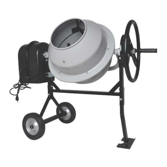
- Page 1 Mini Cement Mixer Owner’s Manual WARNING: Read and understand all instructions, warnings, and cautions before using this product. Failure to follow the instructions, warnings, and cautions may result in serious personal injury and/or property damage. Item # 49414 SAVE THESE INSTRUCTIONS...
- Page 2 Thank you very much for choosing a Klutch product! For future reference, please complete the owner’s record below: Serial Number/Lot Date Code: ________________________________ Purchase Date: ____________________________________________ Save the receipt, warranty, and this manual. This Cement Mixer is designed for certain applications only. Northern...
-
Page 3: Table Of Contents
Table of Contents Intended Use ............................4 Technical Specifications ........................4 Important Safety Information ....................... 5 Grounding .............................. 7 Extension Cords ............................ 8 Assembly Instructions ........................10 Operating Instructions ........................18 Maintenance ............................18 Parts Diagram ............................19 Parts List .............................. 20 Troubleshooting .......................... -
Page 4: Intended Use
Intended Use The Cement Mixer is designed for mixing cement. It is small, efficient, and easy to use. Technical Specifications Motor 120VAC, 60Hz, 200 Watts Motor Speed 1200 RPM Drum Opening 10" (255mm) Drum Rotation Speed 30 RPM Drum Capacity 1.77 cu. -
Page 5: Important Safety Information
Important Safety Information • The warnings, cautions, and instructions in this manual cannot cover all possible conditions or situations that could occur. Exercise common sense and caution when using this tool. Always be aware of the environment and ensure that the tool is used in a safe and responsible manner. •... - Page 6 ELECTRICAL SAFETY • Always check to ensure the power supply corresponds to the voltage on the rating plate. • Do not abuse the cord. Never carry or pull a Cement Mixer by its power cord, or yank power cords or extension cords from the receptacle. Keep power and extension cords away from heat, oil, sharp edges or moving parts.
-
Page 7: Grounding
Grounding Grounded Tools: Tools with 3-Prong Plugs Tools marked with Grounding Required have a 3-wire cord and 3-prong grounding plug. The plug must be connected to a properly grounded outlet. If the tool should electrically malfunction or break down, grounding provides a low resistance path to carry electricity away from the user, reducing the risk of electric shock. -
Page 8: Extension Cords
Extension Cords • Grounded tools require a 3-wire extension cord. Double Insulated tools can use either a 2- or 3-wire extension cord. • As the distance from the supply outlet increases, you must use a heavier gauge extension cord. Using extension cords with inadequately sized wire causes a serious drop in voltage, resulting in loss of power and possible tool damage. - Page 9 CEMENT MIXER USE AND CARE • Do not force the Cement Mixer to perform an operation other than its intended use. Cement Mixers do a better and safer job when used in the manner for which they are designed. Plan your work, and use the correct Cement Mixer for the job.
-
Page 10: Assembly Instructions
Assembly Instructions See Figure A 1. Place Stand (30) onto Hinge Bracket (34) so that the bolt holes line up. 2. Insert Hex Bolts (26) with Washer (27) through the holes from one side, then Washer (27) and Lock Nut (23) from the other side, and tighten with a wrench. 3. - Page 11 See Figure B 5. Place Stand upright. 6. Place Wheel (33) onto Hinge Bracket (34) axle, and slip on the Washer (32) after the wheel. 7. Insert Pins (31) into the Hinge Bracket (34) axle holes, outside each Flat Washer. The pin should be touching the washer, not the wheel.
- Page 12 See Figure D 12. Carefully place the Drum Upper (4) onto the Connector Seal. Make sure that the holes in both align. Note: When placing the Drum Upper, align the Mixing Blade mounting holes in the side of the drums as shown in Figure D. If they are too far away from each other, the Mixing Blades holes will not match up with the mounting holes on the Drums.
- Page 13 See Figure H and Figure I 15. Mount the Degree Adjusting Plate (19) to the Iron Tube (18) using two Hex Bolts (24) with Washer (27) inserted from the outside, and tighten with a wrench. Fig. Ring (17) Iron Tube (17) Fig.
- Page 14 See Figure J 16. Attach Degree Adjusting Wheel (20) to Iron Tube (18) shaft. a. Insert Coil Spring (22) into the lower hole. b. While holding the spring in place, slide the wheel over the iron tube. Note: The Bolt (69) usually have been secured in place, this step may need a little exertion in order to compress the spring sufficient to be able to slip the wheel onto the Iron Tube.
- Page 15 See Figure K and Figure L 18. Mount the inner Motor Base Cover and Motor Mount Plate. a. To prepare the Motor (42) for mounting, remove the Motor from the Inner Motor Base Cover (39) by unthreading the two Hex nuts and Hex bolts holding it in place for shipping. b.
- Page 16 See Figure M 19. Mount the Pulley and Belt. a. Clean the Shaft (35) of all plastic protective material and other debris. Also clean out debris from the Drum Pulley (49) center hole. b. Position the Drum Pulley (49) so that the Set Screw hole (48) is facing outward. Squarely push the Pulley center onto the Shaft so that the groove in the Drum Pulley engages the Key (47).
- Page 17 See Figure N and Figure O. 20. Mount the Motor. WARNING: The Motor is attached to the Outer Motor Base Cover (43) by a power cable. While installing the Motor, have a helper hold the Cover out of the way, without placing tension on the power cable.
-
Page 18: Operating Instructions
Operating Instructions 1. Place the Cement Mixer on a solid, level surface. 2. Connect the Power Cord (44) to an electric outlet (or properly rated grounded three prong extension cord). 3. Add material to the Drum. Typical maximum quantities include: 1 gallon water with 2 shovels of cement and 8 shovels of aggregate rock (using a size 3 shovel, not included). -
Page 19: Parts Diagram
Parts Diagram Page 19 of 24... -
Page 20: Parts List
Parts List Part No. Description Quantity Bolt M8×20 Mixer Blade Washer Φ8 Drum Upper Lock Nut M8 Connector Seal Washer Φ6 Drum Lower Lock Nut M6 Bearing Cover Upper Bearing 6204 Bearing Cover Lower Bearing 6002 Washer Φ15 Iron Tube Fixture Washer Φ38 Ring Φ38 Iron Tube... - Page 21 Part No. Description Quantity Bolt M6×20 Big Washer Φ6 Lock Nut M6 Washer Φ6 Washer Φ6 Bolt M6×20 Bolt M8×60 Switch Plane V Belt 813 Cushion Bolt M8×35 Handle Handgrip Cover Key C5×25 Washer Φ8 Protection Bolt M8×25 Washer Φ5 Nut M5 Page 21 of 24...
-
Page 22: Troubleshooting
Troubleshooting Problem Solution • The Mixer will not turn on. Make sure the power cord is well connected. • Make sure the safety lock 45 is installed. • Reset the overloading protector 68. • Check if the motor works well. •... -
Page 23: Limited Warranty
Northern Tool and Equipment Company, Inc. ("We'' or '"Us'') warrants to the original purchaser only ("You'' or “Your”) that the KLUTCH product purchased will be free from material defects in both materials and workmanship, normal wear and tear excepted, for a period of one year from date of purchase. - Page 24 Distributed by Northern Tool and Equipment Company, Inc. Burnsville, Minnesota 55306 NorthernTool.com Made in China Page 24 of 24...
Need help?
Do you have a question about the 49414 and is the answer not in the manual?
Questions and answers