Table of Contents
Advertisement
Quick Links
Advertisement
Table of Contents

Related Manuals for Klutch 49416


Summary of Contents for Klutch 49416
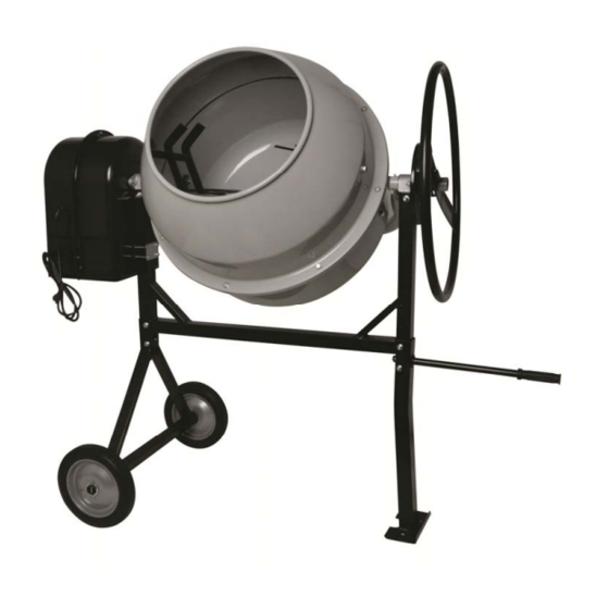
- Page 1 6 Cubic Ft. Cement Mixer Owner’s Manual Read and understand all instructions, warnings, and cautions before using this WARNING: product. Failure to follow the instructions, warnings, and cautions may result in serious personal injury and/or property damage. Item 49416 SAVE THESE INSTRUCTIONS...
- Page 2 Thank you very much for choosing aKlutch product! For future reference, please complete the owner’s record below: Serial Number/LotDate Code: ________________________________ Purchase Date: ____________________________________________ Save the receipt, warranty, and this manual. This Cement Mixer is designed for certain applications only. The distributor cannot be responsible for issues arising from modification or use of this product in an application for which it was not designed.
-
Page 3: Table Of Contents
Table of Contents Intended Use ............................4 Technical Specifications ........................5 Important Safety Information ....................... 6 Grounding .............................. 8 Extension Cords ............................ 9 Assembly Instructions ........................11 Operating Instructions ........................19 Maintenance ............................20 ... -
Page 4: Intended Use
Intended Use The Cement Mixer is designed for mixing cement.This particular model is small, efficient, and easy to transport, making it ideal for both home and jobsite use. Page 4 of 27... -
Page 5: Technical Specifications
Technical Specifications Property Specification 6 Cubic Feet Drum Capacity Drum Opening 15-7/10" Input Power 1 HP 1/2 HP Output Power 1720 Voltage 120 VAC @ 60 Hz, 8.7A 57-1/2"L x 30"W x 53-1/2"H Overall Dimensions Net Weight 145.5 lbs. Page 5 of 27... -
Page 6: Important Safety Information
Important Safety Information The warnings, cautions, and instructions in this manual cannot cover all possible conditions or situations that could occur. Exercise common sense and caution when using this tool. Always be aware of the environment and ensure that the tool is used in a safe and responsible manner. ... - Page 7 ELECTRICAL SAFETY Always check to ensure the power supply corresponds to the voltage on the rating plate. Do not abuse the cord. Never carry or pull a Cement Mixer by its power cord, or yank power cords or extension cords from the receptacle. Keep power and extension cords away from heat, oil, sharp edges or moving parts.
-
Page 8: Grounding
Grounding Grounded Tools: Tools with 3-Prong Plugs Tools marked with Grounding Required have a 3-wire cord and 3-prong grounding plug. The plug must be connected to a properly grounded outlet. If the tool should electrically malfunction or break down, grounding provides a low resistance path to carry electricity away from the user, reducing the risk of electric shock. -
Page 9: Extension Cords
Extension Cords Grounded tools require a 3-wire extension cord. Double Insulated tools can use either a 2- or 3- wire extension cord. As the distance from the supply outlet increases, you must use a heavier gauge extension cord. Using extension cords with inadequately sized wire causes a serious drop in voltage, resulting in loss of power and possible tool damage. - Page 10 CEMENT MIXER USE AND CARE Do not force the Cement Mixer to perform an operation other than its intended use. Cement Mixers do a better and safer job when used in the manner for which they are designed. Plan your work, and use the correct Cement Mixer for the job.
-
Page 11: Assembly Instructions
Assembly Instructions Refer to Figure A 1. Place Stand (30) onto Hinge Bracket (34) so that the bolt holes line up. 2. Insert Hex Bolts (26) with Washer (27) through the holes from one side, then Washer (27) and Lock Nut (23) from the other side, and tighten with a wrench. 3. - Page 12 Refer to Figure C 9. With two people, set the Drum Lower (8) with attached Support Arm assembly into Stand assemblyso that the Shaft (35) is on the wheel side and the Iron Tube (18) is on the Support Bracket (25) side of the assembly. 10.
- Page 13 13. Move the Connector Seal from the inside to make sure the holes of Drum Upper, Connector Seal, and Drum Lower align in a line. Insert Bolt (58) with Washer (57) through the holes and rotate them by hand. Note: Make sure that eight screws are in place, and tighten with a wrench. Connect Seal (6) Bolt (58) &Washer (57) Align the holes...
- Page 14 Refer to Figure J 16. Mount the Degree Adjusting Plate (19) to the Iron Tube (18), using twoHex Bolts (24) with washer (27) inserted from the outside, and tighten with a wrench. (Figure J) Ring (17) Ring (17) Iron Tube (18) Bolt &Washer &locknut Degree adjusting...
- Page 15 Refer to Figure L and Figure M 18. Mount the inner Motor Base Cover and Motor Mount Plate. a. To prepare the Motor (42) for mounting, remove the Motor from the Inner Motor Base Cover (39) by unthreading the two Hex nuts and Hex bolts holding it in place for shipping. b.
- Page 16 Refer to Figure N and Figure O 19. Mount the Pulley and Belt. a. Clean the Shaft (35) of all plastic protective material and other debris. Also clean outdebris fromthe Drum Pulley (49) center hole. b. Position the Drum Pulley (49) so that theSet Screwhole (48) is facing outward. Squarely push the Pulley center onto the Shaft so that the groove in the Drum Pulley engages the Key (47).
- Page 17 Refer to Figure P 20. Mount the Motor. WARNING: The Motor is attached to the Outer Motor Base Cover (43) by a power cable. While installing the Motor, have a helper hold the Cover out of the way, without placing tension on the power cable.
- Page 18 Refer to Figure Q 21. Mount the Outer Motor Base Cover (43) to the Inner Motor Base Cover (39) using three Bolts (46), Washers (70), and Nuts (71). Make sure that the power cord from the Motor to the Switch (45) does not come in contact with moving parts.
-
Page 19: Operating Instructions
Operating Instructions Do not attempt to move the Cement Mixer when it is full and/or in operation. WARNING: Personal injury could result. 1. Place the Cement Mixer on a solid, even surface. 2. Connect the power cord to an electric outlet (or properly rated grounded three prong extension cord). -
Page 20: Maintenance
Maintenance Make sure the Cement Mixer is turned off and disconnected from its power source WARNING: before attempting any maintenance, cleaning, or inspection. Maintain the Cement Mixer by adopting a program of conscientious repair and maintenance in accordance with the following recommended procedures: ... -
Page 21: Parts Diagram
Parts Diagram Page 21 of 27... -
Page 22: Parts List
Parts List Part No. Description Quantity BoltM10×25 Mixer Blade Washer Φ10 Drum Upper Lock Nut M10 Connector Seal BoltM6×12 Drum lower Gearring Bearing sheath Bearing 6206 RingΦ62 Bearing 6002 Washer Φ15 Iron tube fixture Washer Φ38 RingΦ38 Iron tube Degreeadjusting plate Degreeadjusting wheel Lock Nut M10 Coilspring... - Page 23 Part No. Description Quantity Waterproof washer Bolt M8×25 Lock Nut M6 Washer Φ6 Big Washer Φ6 Bolt M6×16 Bolt M8×65 Switch plane V Belt 813 Cushion Washer Φ22 Handle Handgrip cover Key C5×25 Pin Φ5×40 Strengthening cap Washer Φ5 Nut M5 Page 23 of 27...
-
Page 24: Replacement Parts
Replacement Parts For replacement parts and technical questions, please call Customer Service at 1-800-222-5381. Not all product components are available for replacement. The illustrations provided are a convenient reference to the location and position of parts in the assembly sequence. ... -
Page 25: Troubleshooting
Troubleshooting Problem Solution The Mixer will not turn on. Make sure the power cord is well connected. Make sure the safety lock is installed. Check if the motor works well. Make sure the belt on the motor is fastening as always. ... -
Page 26: Limited Warranty
Northern Tool and Equipment Company, Inc. ("We'' or '"Us'') warrants to the original purchaser only ("You'' or “Your”) that the KLUTCH product purchased will be free from material defects in both materials and workmanship, normal wear and tear excepted, for a period of one year from date of purchase. - Page 27 Distributed by Northern Tool and Equipment Company, Inc. Burnsville, Minnesota 55306 NorthernTool.com Made in China Page 27 of 27...
Need help?
Do you have a question about the 49416 and is the answer not in the manual?
Questions and answers