Advertisement
Quick Links
! !
PNSPO!
!
Lean Automation Kit
Quick Start Guide – CP1L-E & NB HMI
Introduction:
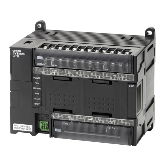
This document describes the procedure to setup your Lean Automation Kit. Your kit
comprises of a CP1L-E Ethernet-equipped PLC, NB-series colour touchscreen HMI
(Ethernet), Westermo SDI-550 5-port Ethernet switch, and S8VS-06024 24VDC power
supply. Optionally, you may have selected a CP1W analogue I/O expansion module and a
JX or MX2 inverter and/or SmartStep2 servomotor system.
You will also have been supplied with all necessary cables and communication modules
for the inverter and/or servo options, a CD containing samples software (for both PLC and
HMI) and a library of technical manuals.
If you have any questions regarding the assembly or operation of your kit, please call:
Technical Support Team: 0870 752 0871
or visit www.myOMRON.com
Scope of Kits:
Each kit contains an NB-series colour touchscreen HMI which is connected to the CP1L-E
PLC via the Westermo 5-port Ethernet switch, using the supplied CAT6 patch cable.
CX-Programmer V8.2 upwards (part of the CX-One V3 or V4 Automation Suite) is required
to program this PLC, which you may have purchased optionally with your kit.
NB-Designer (supplied on the resource CD) is used to program the HMI.
The sample PLC and HMI software applications provided on the resource CD illustrate
how pre-written Function Blocks (FB) simplify the communication process between the
PLC and inverter(s), allowing full control and parameterisation whilst eliminating the need
for traditional digital I/O links between the devices.
For the SmartStep2 servomotor system option, high-speed pulse I/O control is used for
speed and position reference, supported by dedicated PLC instructions. Again, pre-written
PLC and HMI applications are provided on the resource CD to demonstrate these
functions.
revision 2.0 (December 2012)
Advertisement

Subscribe to Our Youtube Channel
Related Manuals for Omron CP1L-E


Summary of Contents for Omron CP1L-E
- Page 1 Scope of Kits: Each kit contains an NB-series colour touchscreen HMI which is connected to the CP1L-E PLC via the Westermo 5-port Ethernet switch, using the supplied CAT6 patch cable. CX-Programmer V8.2 upwards (part of the CX-One V3 or V4 Automation Suite) is required to program this PLC, which you may have purchased optionally with your kit.
- Page 2 OMRON ELECTRONICS LTD ● Technical Support: 0870 752 0871 or visit www.myOMRON.com...
- Page 3 The S8VS-06024 power supply included with your kit is capable of supplying 2.5A at 24VDC, which is intended to supply the required power to the CP1L-E PLC, the NB-series HMI, the Westermo 5-port Ethernet switch and all I/O signals to the inverter and servomotor systems.
- Page 4 S8VS-06024 (Power Supply) 24V 0V 230VAC MAINS SUPPLY L N E CP1L-M30 (PLC) 0V 24V 0V for NPN 24V for PNP NQ3-TQ (HMI – Rear) NQ-CN222 24V 0V OMRON ELECTRONICS LTD ● Technical Support: 0870 752 0871 or visit www.myOMRON.com...
- Page 5 It is not necessary to connect a motor to the JX inverter whilst testing ‘on the bench’. However, if a motor is connected, please refer to the wiring instructions in section 2-2. 230VAC MAINS SUPPLY OMRON ELECTRONICS LTD ● Technical Support: 0870 752 0871 or visit www.myOMRON.com...
- Page 6 4. Remove the CP1W-CIF11 module from the PLC; set the DIP switches (at the rear of the unit) according to the diagram below: Setting the JX communications parameters for MODBUS: OMRON ELECTRONICS LTD ● Technical Support: 0870 752 0871 or visit www.myOMRON.com...
- Page 7 9600 (used in the sample program) from the default of 4800 baud 5. Turn off the power to the JX inverter (setting procedure continued over page…) OMRON ELECTRONICS LTD ● Technical Support: 0870 752 0871 or visit www.myOMRON.com...
- Page 8 7. Turn DIP switch ‘S7’ to the upper ‘485’ position, as indicated in the diagram below (leave switch ‘S8’ in its default OFF position) 8. Replace the front cover and reapply power to the inverter OMRON ELECTRONICS LTD ● Technical Support: 0870 752 0871 or visit www.myOMRON.com...
- Page 9 However, if a motor is connected, please refer to the wiring instructions in section 2-3-12 and earthing/EMC recommendations in section D-1-2 230VAC MAINS SUPPLY from filter to motor captive cables (if used) OMRON ELECTRONICS LTD ● Technical Support: 0870 752 0871 or visit www.myOMRON.com...
- Page 10 ‘SN’ and ‘SP’ terminals of the MX2 and the screw terminals of the CP1W- CIF11 RS422/485 communications option module, fitted in the right-hand slot of the CP1L PLC. OMRON ELECTRONICS LTD ● Technical Support: 0870 752 0871 or visit www.myOMRON.com...
- Page 11 ON position. 4. Remove the CP1W-CIF11 module from the PLC; set the DIP switches (at the rear of the unit) according to the diagram below: OMRON ELECTRONICS LTD ● Technical Support: 0870 752 0871 or visit www.myOMRON.com...
- Page 12 Please refer to section 2-5 of User’s Manual I570-E2-01 if you are unfamiliar with the operation of the front panel keypad. OMRON ELECTRONICS LTD ● Technical Support: 0870 752 0871 or visit www.myOMRON.com...
- Page 13 MX2 inverter. The Omron G9SA-301 safety relay unit is shown wired for manual reset (i.e., the MX2 will not be reset until the button is pressed), but it can, of course, be wired to automatically reset once the E-stop button is released.
- Page 14 Once the E-stop is released and the RESET button has been pressed, the MX2 will revert to normal operation. Please be aware that it could instantly start again if the command inputs and frequency reference remain set. OMRON ELECTRONICS LTD ● Technical Support: 0870 752 0871 or visit www.myOMRON.com...
- Page 15 2. Connect the output power connector from the filter into ‘CNA’ of the servo amplifier. Attach the flying earth cable eyelet to one of the two earthing screws to the left side of this connector. OMRON ELECTRONICS LTD ● Technical Support: 0870 752 0871 or visit www.myOMRON.com...
- Page 16 5. Attach the control I/O cable (R7A-CPB001S) into terminal ‘CN1’ of the servo amplifier and secure the retaining screws. OMRON ELECTRONICS LTD ● Technical Support: 0870 752 0871 or visit www.myOMRON.com...
- Page 17 Connect the off-cut of this cable to the other side of the resistor module, then to output 100.01 – this is the ‘COUNTER CLOCKWISE PULSES’ command signal. OMRON ELECTRONICS LTD ● Technical Support: 0870 752 0871 or visit www.myOMRON.com...
- Page 18 11. Connect the GREY (1 RED BAND) wire to output 100.07 – this is the ‘RESET’ signal to the drive, to be used after an error. OMRON ELECTRONICS LTD ● Technical Support: 0870 752 0871 or visit www.myOMRON.com...
- Page 19 SmartStep2 servo amplifier to PLC wiring; PNP CONFIGURATION FOR CP1L-M30DT1-D MODEL OMRON ELECTRONICS LTD ● Technical Support: 0870 752 0871 or visit www.myOMRON.com...
- Page 20 11. Connect the GREY (1 RED BAND) wire to output 100.07 – this is the ‘RESET’ signal to the drive, to be used after an error. OMRON ELECTRONICS LTD ● Technical Support: 0870 752 0871 or visit www.myOMRON.com...
- Page 21 SmartStep2 servo amplifier to PLC wiring; NPN CONFIGURATION FOR CP1L-M30DT-D MODEL OMRON ELECTRONICS LTD ● Technical Support: 0870 752 0871 or visit www.myOMRON.com...
- Page 22 SmartStep2 servo amplifier to PLC wiring; PNP CONFIGURATION FOR CP1L-EM30DT1-D MODEL OMRON ELECTRONICS LTD ● Technical Support: 0870 752 0871 or visit www.myOMRON.com...
- Page 23 “CX-One” software installation; Omron’s CX-One is a suite of software for programming Omron PLCs, HMIs, ac drives, servo and motion control systems and many other components. It also features a fully-integrated simulation tool, CX-Simulator, allowing you to create and test your PLC and HMI software “off line” without the need for the physical hardware.
- Page 24 If you download the latest version from www.myOMRON.com, you will need to ‘unzip’ the compressed download file. Run the “setup.exe” file and follow the instructions to install NQ-Designer OMRON ELECTRONICS LTD ● Technical Support: 0870 752 0871 or visit www.myOMRON.com...
- Page 25 Downloading the demonstration software; CP1L PLC program… Open CX-Programmer from Start > Programs > OMRON > CX-One > CX- Programmer… Launch the application, then select File > Open Browse to the SOFTWARE folder on the Resource CD > CP1L PLC DEMO >...
- Page 26 Windows will then install the USB driver for the PLC… If you see the screen below (which depends upon your version of Windows), click Continue Anyway… Click Finish to complete the installation… OMRON ELECTRONICS LTD ● Technical Support: 0870 752 0871 or visit www.myOMRON.com...
- Page 27 From the top-level PLC menu, select Transfer > To PLC. Ensure that all boxes are ‘checked’ (as shown below), then click OK… You will be asked if you wish to continue; click Yes… OMRON ELECTRONICS LTD ● Technical Support: 0870 752 0871 or visit www.myOMRON.com...
- Page 28 With either of the above, the PLC’s POWER and RUN LED indicators should both be lit green. Now follow the next steps to download the application to the NQ3 HMI… OMRON ELECTRONICS LTD ● Technical Support: 0870 752 0871 or visit www.myOMRON.com...
- Page 29 Further details can be found on page 20 of the “V07-EN-01 NQ Getting Started Guide” (see Resource CD > TECHNICAL DOCUMENTATION > NQ-SERIES HMI) From the Project menu, select Transfer then Download… OMRON ELECTRONICS LTD ● Technical Support: 0870 752 0871 or visit www.myOMRON.com...
- Page 30 HMI and PLC. You are now ready to run the demonstration software! OMRON ELECTRONICS LTD ● Technical Support: 0870 752 0871 or visit www.myOMRON.com...
- Page 31 PLC program. Just touch the thumbnail picture of the products you have, and a ‘tick’ will appear to confirm its selection. These choices are retained within the PLC, so do not need to be re-selected every time you re-power the system. OMRON ELECTRONICS LTD ● Technical Support: 0870 752 0871 or visit www.myOMRON.com...
- Page 32 Pressing the top-right “next” arrow takes you on to the inverter monitoring screen… The advantage of controlling drives by communications over a network is that all the status information for each unit can be monitored. OMRON ELECTRONICS LTD ● Technical Support: 0870 752 0871 or visit www.myOMRON.com...
- Page 33 Note that “AT ZERO SPEED” and “UNDER-VOLTAGE DETECT” are only available for the MX2 model. Pressing the blue “info” symbol on the main control screen brings up the following screen; OMRON ELECTRONICS LTD ● Technical Support: 0870 752 0871 or visit www.myOMRON.com...
- Page 34 The blue “info” button brings up the following three screens which explain the operation symbols panel which appears on each of the servo control screens… OMRON ELECTRONICS LTD ● Technical Support: 0870 752 0871 or visit www.myOMRON.com...
- Page 35 PLC ‘sees’ the Z-phase marker. Once completed, the “AT ORG” indicator on the HMI screen will light green to indicate that the system has successfully performed an origin search. OMRON ELECTRONICS LTD ● Technical Support: 0870 752 0871 or visit www.myOMRON.com...
- Page 36 PLC because of a mechanical problem or the motor becoming disconnected from the servo amplifier. OMRON ELECTRONICS LTD ● Technical Support: 0870 752 0871 or visit www.myOMRON.com...
- Page 37 “IN POSN” indicator will extinguish to indicate that the motor is moving. “IN POSN” will re-light when the movement profile has been completed. OMRON ELECTRONICS LTD ● Technical Support: 0870 752 0871 or visit www.myOMRON.com...
- Page 38 “IN POSN” indicator will extinguish to indicate that the motor is moving. “IN POSN” will re-light when the movement profile has been completed. OMRON ELECTRONICS LTD ● Technical Support: 0870 752 0871 or visit www.myOMRON.com...
- Page 39 The CD supplied with the Lean Kit contains the demonstration software for PLC and HMI, a copy of NQ-Designer programming software, brochures and datasheets, and technical documentation (User Manuals, Programming Manuals, etc) for all products; Additional information can be found at www.industrial.omron.co.uk OMRON ELECTRONICS LTD ● Technical Support: 0870 752 0871 or visit www.myOMRON.com...
- Page 40 PNSPO JX-MX2 INVERTER REFRESH FUNCTION BLOCK An introduction to the JX/MX2 Inverter Refresh Function Block - Controlling up to 31 Inverters using MODBUS communication over 2-wire RS485 OMRON ELECTRONICS LTD ● Technical Support: 0870 752 0871 or visit www.myOMRON.com...
- Page 41 JX-MX2 INVERTER REFRESH FUNCTION BLOCK #CCCC means that we’re using this Function Block with a CP- series PLC and &2 means that the CP1W-CIF11 RS422/485 module is located in Port 2 OMRON ELECTRONICS LTD ● Technical Support: 0870 752 0871 or visit www.myOMRON.com...
- Page 42 30 29 28 27 26 25 24 23 22 21 20 19 18 17 16 15 14 13 12 11 10 09 08 07 06 05 04 03 02 01 06 05 06 05 D1003 D1002 OMRON ELECTRONICS LTD ● Technical Support: 0870 752 0871 or visit www.myOMRON.com...
- Page 43 30 29 28 27 26 25 24 23 22 21 20 19 18 17 16 15 14 13 12 11 10 09 08 07 06 05 04 03 02 01 D1001 D1000 OMRON ELECTRONICS LTD ● Technical Support: 0870 752 0871 or visit www.myOMRON.com...
- Page 44 DM100.02 DM100.03 DM103 DM100.04 DM104 DM100.05 DM105 DM106 DM107 DM100.08 DM108 DM109 DM100.09 DM110 DM100.10 DM111 DM162 DM163 DM100.13 DM100.14 DM100.15 DM101 = Freq Ref for Node #01 OMRON ELECTRONICS LTD ● Technical Support: 0870 752 0871 or visit www.myOMRON.com...
- Page 45 PNSPO CONTROLLING SMARTSTEP2 WITH CP1 PLC Using just three instructions for complete control of the SMARTSTEP2 servo OMRON ELECTRONICS LTD ● Technical Support: 0870 752 0871 or visit www.myOMRON.com...
- Page 46 NQ3 HMI, and the pulses are output as long as you keep your finger on the button. When you release it, the ‘INI’ instruction is executed, stopping the pulses. OMRON ELECTRONICS LTD ● Technical Support: 0870 752 0871 or visit www.myOMRON.com...
- Page 47 The ‘specified number of pulses’ (which equates to a physical movement distance) and ‘target frequency’ are input from the HMI OMRON ELECTRONICS LTD ● Technical Support: 0870 752 0871 or visit www.myOMRON.com...
- Page 48 SMARTSTEP2 amplifier) will prevent damage to the system if you send too many pulses. OMRON ELECTRONICS LTD ● Technical Support: 0870 752 0871 or visit www.myOMRON.com...
- Page 49 ‘ORG’, absolute positioning cannot be performed. The use of the instruction is identical to relative positioning, apart from the setting of one ‘bit’. OMRON ELECTRONICS LTD ● Technical Support: 0870 752 0871 or visit www.myOMRON.com...
Need help?
Do you have a question about the CP1L-E and is the answer not in the manual?
Questions and answers