CyberPower AVR Series User Manual
Hide thumbs
Also See for AVR Series:
- User manual (5 pages) ,
- User manual (12 pages) ,
- User manual (2 pages)
Advertisement
Quick Links
YOUR ULTIMATE ALLY IN POWER
AVR UPS SERIES
USER MANUAL
1
3
4
FEATURES
1.
Power Switch
2.
Power On Indicator
3.
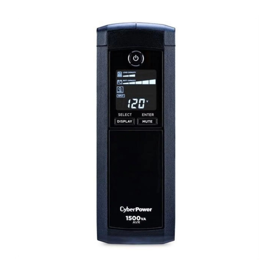
LCD Module Display
4.
Display/Select Button
5.
Mute/Enter Button
6.
Battery and Surge Protected Outlet
PRODUCT REGISTRATION
Thank you for purchasing a CyberPower product. This UPS is designed to provide unsurpassed
power protection, operation, and performance during the lifetime of the product. Please take
a few minutes to register your product at: www.CyberPowerSystems.com/registration. Regis-
tration certifies your product's warranty, confirms your ownership in the event of a product loss
or theft, and entitles you to free technical support. Register your product now to receive the
benefits of CyberPower ownership.
Cyber Power Systems (USA), Inc.
4241 12th Avenue East, Suite 400 | Shakopee, MN 55379 | CyberPowerSystems.com
INSTALLING YOUR UPS SYSTEM
OVERVIEW
The A1500SP1 provides complete power pro-
tection from utility power that is not always
consistent. The A1500SP1 features 1500 Joules
of surge protection. The unit ensures consis-
tent power to your sump pump and provides
long lasting battery backup during power
outages with maintenance free batteries.
HARDWARE INSTALLATION GUIDE
1. Your new UPS may be used immediately
upon receipt. However, after receiving a
new UPS, to ensure the battery's maximum
charge capacity, it is recommended that
you charge the battery for at least 8 hours.
Your UPS is equipped with an auto-charge
feature. When the UPS is plugged into an
AC outlet, the battery will automatically
charge whether the UPS is turned on or off.
2. Note: This UPS is designed with a safety
feature to keep the system from being
turned on during shipment. The first time
you turn the UPS on, you will need to have
it connected to AC power or it will not
power up.
3. Elevate the UPS at least 18 inches above the
floor on a stable surface like a table or shelf.
4. Ensure the wall outlet and UPS are locat-
ed near the equipment being attached for
proper accessibility.
5. With the UPS unit turned off and un-
plugged, connect your sump pump into
the battery power supplied outlet closest
to the top of the unit. This unit will work
with sump pumps up to 1/2 HP in size. DO
NOT plug any additional equipment into
the UPS, as any additional power demands
may overload and damage the UPS.
BASIC OPERATION
1. Power Switch
Used as the master on/off switch for equip-
ment connected to the battery power sup-
plied outlets. (Please refer to the Function
Setup Guide for more information.)
2. Power On Indicator
This LED is illuminated when the utility
power is normal and the UPS outlets are
providing power, free of surges and spikes.
3
A1500SP1
9
8
11
2
10
6
7
5
7.
Circuit Breaker
8.
Serial/USB Ports to PC
9.
Communication Protection Ports
10. Wiring Fault Indicator (red)
11.
Coax/Cable/DSS Surge Protection
- continued
Plug in
6. Plug the UPS into a
2-pole, 3-wire grounded
receptacle (wall outlet).
Make sure the wall branch
outlet is protected by a fuse or circuit
breaker and does not service equipment
with large electrical demands (e.g. air
conditioner, copier, etc...). The warranty
prohibits the use of extension cords, outlet
strips, and surge strips.
7. Press the power switch to turn the unit on.
The Power On indicator light will illuminate
and the unit will "beep". If an overload is
detected, an audible alarm will sound and
the unit will emit one long beep. To correct
this, turn the UPS off and ensure that the
sump pump is no large than 1/2 HP in size
and that no other devices are plugged into
the unit. Make sure the circuit breaker is
depressed and then turn the UPS on.
8. To maintain optimal battery charge, leave
the UPS plugged into an AC outlet at all
times.
9. To store the UPS for an extended period,
cover it and store with the battery fully
charged. While in storage, recharge the
battery every three months to ensure
battery life.
3. LCD module display
The LCD display shows all the UPS informa-
tion using icons and messages. For more
information please review the "Definitions
for Illuminated LCD Indicators" section
below.
IMPORTANT SAFETY WARNINGS
This manual contains important safety instructions. Please read and follow all instructions carefully
during installation and operation of the unit. Read this manual thoroughly before attempting to
unpack, install, or operate your UPS.
CAUTION! To prevent the risk of fire or
electric shock, install in a temperature and
humidity controlled indoor area free of
conductive contaminants. (Please see
specifications for acceptable temperature
and humidity range).
CAUTION! To reduce the risk of electric shock,
do not remove the cover except to service the
battery. Turn off and unplug the unit before
servicing the batteries. There are no user ser-
viceable parts inside except for the battery.
CAUTION! Hazardous live parts inside can be
energized by the battery even when the AC
input power is disconnected.
CAUTION! The UPS must be connected to an
AC power outlet with fuse or circuit breaker
protection. Do not plug into an outlet that is
not grounded. If you need to de-energize this
equipment, turn off and unplug the unit.
CAUTION! To avoid electric shock, turn off the
unit and unplug it from the AC power source
before connecting equipment to the unit.
CAUTION! To reduce the risk of fire, connect
only to a circuit provided with 20 amperes
maximum branch circuit over current protec-
tion in accordance with the National Electric
Code, ANSI/NFPA 70.
INSTALLING YOUR UPS SYSTEM
UNPACKING
Inspect the UPS upon receipt.
The box should contain the following:
(a) UPS unit
(b) User's manual
(c) USB A+B type cable
(d) Function Setup Guide
PowerPanel® Personal software is
available on our website. Please visit
www.cyberpowersystems.com and go
to the Software Section for a free download.
BASIC OPERATION
4. Display/Select Button
The button can be used to select the LCD
display contents including Input Voltage,
and output Voltage. Short press the button
to scroll down the function menu. Pressing
the button for 3 seconds will keep the LCD
display always on or turn the LCD display
off while in AC/Utility power mode. (Please
refer to the Function Setup Guide for more
information.)
5. Mute/Enter Button
Holding the button for more than 3 sec-
onds will silence the alarm. Short press the
ENTER button to confirm the setting.
After the setting has been confirmed, the
LCD screen will stop flashing. (Please refer
to the Function Setup Guide for more
information.)
6. Battery and Surge Protected Outlet
The UPS has one battery powered/surge
suppression outlet to ensure temporary un-
interrupted operation of your sump pump
during a power failure.
7. Circuit Breaker
Located on the back of the UPS, the circuit
breaker serves to provide overload and
fault protection.
REPLACING THE BATTERY
Replacement of batteries located
in an OPERATOR ACCESS AREA
1. When replacing batteries, replace with
the same number of the following battery:
CyberPower / RB1290X2 for A1500SP1.
2. CAUTION! Risk of Energy Hazard, 24V,
maximum 9 Ampere hour battery. Before
replacing batteries, remove conductive
jewelry such as chains, wrist watches, and
rings. High energy through conductive ma-
terials could cause severe burns.
3. CAUTION! Do not dispose of batteries in a
fire. The batteries may explode.
4. CAUTION! Do not open or mutilate batter-
ies. Released material is harmful to the skin
and eyes. It may be toxic.
-continued
(SAVE THESE INSTRUCTIONS)
CAUTION! Not for use in a computer room as
defined in the Standard for the Protection of
Electronic Computer / Data Processing Equip-
ment, ANSI/NFPA 75.
CAUTION! Do not dispose of batteries in a fire.
The batteries may explode.
CAUTION! Do not open or mutilate batteries.
Released electrolyte is harmful to the skin and
eyes. It may be toxic.
DO NOT USE FOR MEDICAL
OR LIFE SUPPORT EQUIPMENT!
CyberPower Systems does not sell products
for life support or medical applications. DO
NOT use in any circumstance that would affect
operation and safety of life support equip-
ment, any medical applications or patient care.
DO NOT USE WITH OR NEAR AQUARIUMS!
To reduce the risk of fire or electric shock, do
not use with or near an aquarium. Condensa-
tion from the aquarium can cause the unit to
short out.
DO NOT USE THE UPS
ON ANY TRANSPORTATION!
To reduce the risk of fire or electric shock, do
not use the unit on any transportation such
as airplanes or ships. The effect of shock or
vibration caused during transit and the damp
environment can cause the unit to short out.
AUTOMATIC VOLTAGE REGULATOR
The A1500SP1 stabilizes inconsistent utility pow-
er to nominal levels that are safe for equipment.
Unstable utility power can be damaging to
important data and hardware. With Automatic
Voltage Regulation (AVR), damaging voltage
levels are corrected to safe levels. AVR automat-
ically increases low utility
power to a consistent and
safe 110/120 volts.
- continued
8. Serial/USB Ports to PC
The USB port allows connection and com-
munication between the USB port on the
computer and the UPS unit.
9. Communication Protection Ports
Communication protection ports, bi-direc-
tional, will protect a 10/100/1000 Ethernet
connection (RJ45).
10. Wiring Fault Indicator (red)
This LED indicator will illuminate to warn
the user that a wiring problem exists, such
as bad ground, missing ground or reversed
wiring. If this is illuminated, disconnect all
electrical equipment from the outlet and
have an electrician verify the outlet is prop-
erly wired. The UPS will not provide surge
protection without being plugged into a
grounded and properly wired wall outlet.
11. Coax/Cable/DSS Surge Protection
The Coax/Cable/DSS protection ports will
protect any cable modem, CATV converter,
or DSS receiver.
5. CAUTION! A battery can present a risk of
electrical shock and high short circuit cur-
rent. The following precautions should be
observed when working on batteries:
(1) Remove watches rings, or other metal
objects.
(2) Use tools with insulated handles.
CAUTION - RISK OF EXPLOSION IF BATTERY
IS REPLACED BY AN INCORRECT TYPE.
DISPOSE OF USED BATTERIES ACCORDING
TO LOCAL REGULATIONS.
2
4
Advertisement

Related Manuals for CyberPower AVR Series


Summary of Contents for CyberPower AVR Series
- Page 1 (b) User’s manual Voltage Regulation (AVR), damaging voltage (c) USB A+B type cable Thank you for purchasing a CyberPower product. This UPS is designed to provide unsurpassed levels are corrected to safe levels. AVR automat- (d) Function Setup Guide power protection, operation, and performance during the lifetime of the product. Please take ically increases low utility PowerPanel®...
- Page 2 The application of the United Nations Convention of Contracts for the International Sale of Goods is expressly excluded. CyberPower is the warrantor under this Limited Warranty. For further information please feel free to contact CyberPower at: Cyber Power Systems (USA), Inc. 4241 12th Ave E., STE 400, Shakopee, MN 55379;...
Need help?
Do you have a question about the AVR Series and is the answer not in the manual?
Questions and answers