Table of Contents
Advertisement
Quick Links
Advertisement
Table of Contents

Related Manuals for ARRI DEP-1


Summary of Contents for ARRI DEP-1
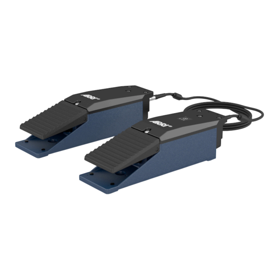
- Page 1 Digital Encoder Pedals DEP-1 U S E R M A N U A L 01.07.2022...
-
Page 2: Disclaimer
In no event shall ARRI or its subsidiaries be liable for or have a remedy for recovery of any special, direct, indirect, incidental, or consequential damages, including, but not limited to lost profits, lost savings, lost... -
Page 3: Imprint
The information and intellectual property contained herein is confidential between ARRI and the client and remains the exclusive property of ARRI. If you find any problems in the documentation, please report them to us in writing. ARRI does not warrant that this document is flawless. -
Page 4: Table Of Contents
Host and Client Pedal Setup..................18 Analog Connection......................18 LBUS Connection and Cables..................18 Assigning functions......................19 Remote Control Setup....................19 8.6.1 Assigning the Digital Encoder Pedals DEP-1.............. 19 8.6.2 Additional Controls Setup..................... 20 8.6.3 Dead Band........................20 8.6.4 Sensitivity for Control Devices..................20 8.6.5... -
Page 5: About This Document
About this Document About this Document This user manual is aimed at everyone involved in using the system and provides directions on how to operate it safely and as intended. To ensure safe and correct use, all users must read the user manual before using the accessories for the first time. -
Page 6: About The Product
The Digital Encoder Pedals DEP-1, represent another new member of the LBUS controller range. What does it do? With a pair of the Digital Encoder Pedals DEP-1 you can control a selected axis of the Stabilized Remote Head, like Tilt-Pan, Roll, or a selected axis of the focus, iris, or zoom function. -
Page 7: Identification
L 9.92“ - W 2.75“ - H 2.75“ Power supply voltage: 10,5 V – 33,6 V DC Max. 4A Interfaces: DEP-1 Master LBUS 2x 4pin Lemo / 24V max. 4 A Analog In 3pin Fischer / 12V max. 1 A... -
Page 8: Dimensional Of Drawing
About the Product Peli Case Air 1507 Foam inlay dimensions for : L 385mm - W 289mm - H 216mm L 15.15“ - W 11.38“ - H 8.5“ Pin Out LBUS Analog In / Out Dimensional of Drawing... -
Page 9: Scope Of Delivery And Warranty
On delivery, please check if package and content are intact. Never accept a damaged delivery. Warranty For scope of warranty, please ask your local ARRI Service Partner. ARRI is not liable for consequences from inadequate shipment, improper use or third-party products. - Page 10 Brand Name: ARRI Product Description: Digital Encoder Pedals DEP-1 The designated products conform to the specifications of the following European directives: Directive 2014/30/EU of the European Parliament and the Council of 26 February 2014 on the harmonization of the laws of the Member States relating to electromagnetic compatibility...
- Page 11 About the Product radiate radio frequency energy and, if not installed and used in accordance with the instructions, may cause harmful interference to radio communications. However, there is no guarantee that interference will not occur in a particular installation. If this equipment does cause harmful interference to radio or television reception, which can be determined by turning the equipment off and on, the user is encouraged to try to correct the interference by one or more of the following measures: Reorient or relocate the receiving antenna.
-
Page 12: Safety Instructions
Safety Instructions Safety Instructions This safety information is in addition to the product specific operating instructions in general and must be strictly observed for safety reasons. Read and understand all safety and operating instructions before you operate or install the system. Retain all safety and operating instructions for future reference. -
Page 13: General Safety Instructions
General Safety Instructions WARNING Operating the Digital Encoder Pedals DEP-1 in case of obvious damage Risk of electric shock and fire hazard caused by short circuit. Do not use the system if electrical lines or housing are visibly damaged. - Page 14 Do not place any unauthorized objects on the camera accessories. Do not hang any unauthorized objects on the camera accessories. Use only accessories approved by ARRI. The use of accessories not approved by ARRI is at your own risk. Please observe all relevant safety guidelines...
- Page 15 May cause physical impairments such as sleep disturbances and stress. Follow the manufacturer's instructions. Use only camera accessories approved by ARRI. The use of accessories not approved by ARRI is at your own risk. Please observe all relevant safety guidelines.
-
Page 16: Overview Digital Encoder Pedals Dep-1
Overview Digital Encoder Pedals DEP-1 Overview Digital Encoder Pedals DEP-1 Top View Back View... -
Page 17: Installation And Operation
When using the system on camera cranes, a suitable safety rope must be used. Use only accessories approved by ARRI. The use of accessories not approved by ARRI is at your own risk. Please observe all relevant safety guidelines. -
Page 18: Host And Client Pedal Setup
Do not insert objects. ATTENTION Visit the ARRI website to verify that all of the controllers you plan to use have the latest firmware. The entire digital communication of the Digital Encoder Pedals DEP-1 is based on the LBUS. LBUS is an ARRI/cmotion bus standard designed to allow multiple lens motors and control devices to communicate with each other. -
Page 19: Assigning Functions
Remote Control Setup ATTENTION The Digital Encoder Pedals DEP-1 shall be assigned to the corresponding axes of the remote head. 8.6.1 Assigning the Digital Encoder Pedals DEP-1 For a fast selection, the home screen of the remote control offers a short cut. -
Page 20: Additional Controls Setup
Dead Band ATTENTION If the Digital Encoder Pedals DEP-1 are used as a controller, Deadband shall be set to 0 - 3. Higher values can cause unwanted lag of response. Selecting Deadband opens a new touchscreen slider that allows to change the Deadband values on the selected axis. -
Page 21: Filter
ATTENTION A too high filter value may cause a delay in response. When the DEP-1 is used in a car or a train, vibrations of the vehicle may be transmitted to the DEP-1's encoders.This can lead to irritations in the pan and tilt axis. -
Page 22: Cleaning And Repair
Repairs carried out by Untrained Personnel Risk of electric shock and fire caused by short circuit. Do not try to repair the device yourself. Repairs may only be carried out by authorized ARRI service partners. For repairs and maintenance work on the camera system, please contact "ARRI... -
Page 23: Transportation And Storage
Follow the specified environmental conditions. Do not store the accessories in places where they may be subject to temperature extremes, direct sunlight, high humidity, severe vibration or strong magnetic fields. If you have any questions regarding the transport or storage of ARRI products, please contact "ARRI Service". -
Page 24: Disposal
Disposal Disposal ATTENTION The product can be returned to the manufacturer. This product falls within the scope of Directive 2012/19 / EU OF THE EUROPEAN PARLIAMENT AND OF THE COUNCIL of June 4, 2012 on waste electrical and elec- tronic equipment (WEEE II). Accordingly, this product must not be disposed of with household waste. -
Page 25: Arri Service Contacts
ARRI Service Contacts ARRI Service Contacts Arnold & Richter Cine Technik ARRI CT Limited / London GmbH & Co. Betriebs KG 2 Highbridge, Oxford Road Herbert-Bayer-Str. 10 UB8 1LX Uxbridge 80807 Munich United Kingdom Germany +44 1895 457 000 +49 89 3809 2121... - Page 26 ARRI Service Contacts CINEOM Broadcast DMCC. CINEOM Broadcast India Pvt. Ltd. Unit No. 2109, Jumeirah Bay Tower X2 Cluster X C-4, Goldline Business Centre Jumeirah Lakes Towers Link Rd. Malad West P.O Box 414659 400 064 Mumbai Dubai, UAE India...
Need help?
Do you have a question about the DEP-1 and is the answer not in the manual?
Questions and answers