Table of Contents
Advertisement
Quick Links
Advertisement
Table of Contents

Related Manuals for Aaeon SRG-IMX8P


Summary of Contents for Aaeon SRG-IMX8P
- Page 1 SRG-IMX8P IOT Gateway System User’s Manual 1...
- Page 2 AAEON assumes no liabilities resulting from errors or omissions in this document, or from the use of the information contained herein. AAEON reserves the right to make changes in the product design without notice to its users.
- Page 3 Acknowledgment The following product names and trademarks are properties of their respective owners: Microsoft Windows is a registered trademark of Microsoft Corp. ⚫ Intel is a registered trademark of Intel Corporation ⚫ ARM, Cortex, and Cortex-A53 are registered trademarks of Arm Limited (or its ⚫...
- Page 4 Packing List Before setting up your product, please make sure the following items have been shipped: Item Quantity SRG-IMX8P ⚫ If any of these items are missing or damaged, please contact your distributor or sales representative immediately. Preface...
- Page 5 (if any), its specifications, dimensions, jumper/connector settings/definitions, and driver installation instructions (if any), to facilitate users in setting up their product. Users may refer to the product page at AAEON.com for the latest version of this document. Preface...
- Page 6 Safety Precautions Please read the following safety instructions carefully. It is advised that you keep this manual for future references All cautions and warnings on the device should be noted. Make sure the power source matches the power rating of the device. Position the power cord so that people cannot step on it.
- Page 7 If any of the following situations arises, please the contact our service personnel: Damaged power cord or plug Liquid intrusion to the device iii. Exposure to moisture Device is not working as expected or in a manner as described in this manual The device is dropped or damaged Any obvious signs of damage displayed on the device...
- Page 8 FCC Statement This device complies with Part 15 FCC Rules. Operation is subject to the following two conditions: (1) this device may not cause harmful interference, and (2) this device must accept any interference received including interference that may cause undesired operation. Caution: There is a danger of explosion if the battery is incorrectly replaced.
- Page 9 China RoHS Requirements (CN) 产品中有毒有害物质或元素名称及含量 AAEON System QO4-381 Rev.A0 有毒有害物质或元素 部件名称 铅 汞 镉 六价铬 多溴联 多溴二苯 苯(PBB) 醚(PBDE) (Pb) (Hg) (Cd) (Cr(VI)) 印刷电路板 × ○ ○ ○ ○ ○ 及其电子组件 外部信号 × ○ ○ ○ ○ ○ 连接器及线材 外壳...
- Page 10 China RoHS Requirement (EN) Hazardous and Toxic Materials List AAEON System QO4-381 Rev.A0 Hazardous or Toxic Materials or Elements Component Name PCB and Components Wires & Connectors for Ext. Connections Chassis CPU & RAM HDD Drive LCD Module Optical Drive...
-
Page 11: Table Of Contents
Table of Contents Chapter 1 - Product Specifications..................1 Specifications ......................2 Chapter 2 – Hardware Information ..................4 Dimensions ....................... 5 I/O Location ......................6 List of Connectors ....................7 2.3.1 DC Power (1) ....................8 2.3.2 HDMI Port (2) ....................8 2.3.3 USB 3.0 Port (3) .................... - Page 12 3.2.2 To Delete a User Account................. 24 I/O Management ....................25 CAN-FD Pin Definition..................26 Pin Definition: RS-232/422/485 x 2 ..............28 Network Settings ....................30 3.6.1 Check the IP Setting .................. 30 3.6.2 Set the Static IP ................... 31 3.6.3 Set the Dynamic IP ..................
-
Page 13: Chapter 1 - Product Specifications
Chapter 1 Chapter 1 - Product Specifications... -
Page 14: Specifications
Specifications System Processor ARM® NXP i.MX8M Plus Quad-Core Cortex®-A53 1.6GHz Processor Memory Onboard DDR4L 2GB (Optional 4GB) Storage eMMC 16G (Optional 32GB) Real Time Clock RTC x 1, with 3V CR2032 Lithium battery Security TPM 2.0 Indicators Programmable LED control x 7 Cellular Mini PCIe Connector x 1 (USB signal) Wireless LAN... - Page 15 Power Supply Power Requirement DC 9-36V Power Consumption 9.36W (Full Loading) MTBF (Hours) 479,374 Environmental Dimension 5.54’' x 3.86” x 1.89” (140.76mm x 98.2mm x 48mm) Weight 2.1 lbs. (0.95Kg) Mount Options Wall Mount, Din Rail (Optional) Operation Temperature -4 °F ~ 158 °F (-20 °C ~ 70 °C) Storage Temperature -40 °F ~ 176 °F (-40 °C ~ 80 °C) Operation Humidity...
-
Page 16: Chapter 2 - Hardware Information
Chapter 2 – Hardware Information Chapter 2... -
Page 17: Dimensions
Dimensions Chapter 2 – Hardware Information... -
Page 18: I/O Location
I/O Location Chapter 2 – Hardware Information... -
Page 19: List Of Connectors
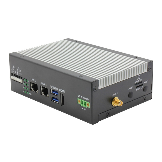
List of Connectors The SRG-IMX8P features several connectors which can be configured for your application. This section details those connections and their specifications. Label Function DC Power HDMI Port USB 3.0 Port Giga LAN Port Indicators Light CAN-FD Port Reset Button... -
Page 20: Dc Power (1)
2.3.1 DC Power (1) The gateway can accept DC 9-36V input though 2 pin phoenix connector. 2.3.2 HDMI Port (2) The HDMI support port enables video output to an external display. 2.3.3 USB 3.0 Port (3) The USB 3.0 is a type A connector, and can also support USB mass storage. Chapter 2 –... -
Page 21: Giga Lan Port (4)
2.3.4 Giga LAN Port (4) The standard RJ-45 LAN jack is provided the connection to the Local Area Network (LAN). Function Status Yellow Active status ON: LAN link is established. OFF: LAN link is not established. Blink: Data received and transmitted. Green on: 100Mbps. -
Page 22: Indicators Light (5)
2.3.5 Indicators Light (5) User can control the 7 LED via the GPIO. The control command for LED 1-7: Control Command Turn On m0cli -c 0 -i 1 -v 1 Turn Off m0cli -c 0 -i 1 -v 0 Note: i: LED number. Chapter 2 –... -
Page 23: Can-Fd Port (6)
2.3.6 CAN-FD Port (6) Provides two phoenix CANbus ports for external device connection. Check chapter 3 for more information. 2.3.7 Reset Button (7) Press the button to reboot the OS. Chapter 2 – Hardware Information... -
Page 24: Rs-232/422/485 Port (8)
2.3.8 RS-232/422/485 Port (8) Provides two phoenix connectors for RS-232/422/485 interface. Check chapter 3 for more information. 2.3.9 Micro SIM Slot (9) User can insert the micro SIM card into the slot when using an LTE module via the mini card slot. Chapter 2 –... -
Page 25: Micro Sd Slot (10)
2.3.10 Micro SD Slot (10) User can increase the available storage by insert the micro SD card. 2.3.11 Antenna (11) The 3 Antenna configurations are Wi-Fi, 4G, or LTE. Chapter 2 – Hardware Information... -
Page 26: Debug Port (12)
2.3.12 Debug Port (12) Log into the gateway’s Linux OS via SSH via debug port (Micro USB type). Serial Port Settings Baud rate 115200 bps Parity None Data bits Stop bits Flow Control None See chapter 3 for further information. Chapter 2 –... -
Page 27: Wireless Hardware Setup
Wireless Hardware Setup The SRG-IMX8P features both a SIM Card and Mini Card slot for connecting to wireless networks such as 4G/LTE, and Wi-Fi. This section details how to install a SIM Card, 4G/LTE module, and Wi-Fi module. 2.4.1 Mini Card Installation Step 1: Remove top cover by first removing the 10 screws securing the cover. - Page 28 Step 2: Remove the plugs from the antenna holes: Step 3: Install the RF coaxial cables on the antenna holes. Chapter 2 – Hardware Information...
- Page 29 Step 4: Install Mini Card Insert the 4G/LTE, or Wi-Fi/BT module into the slot and connect the RF coaxial cable to the module. Note: The installation slots are the same as the photo. Item Module Installation Location Wi-Fi WPET-236ACN(BT) Install the RF cable to left conn. to support Wi-Fi module signal.
-
Page 30: Sim Card Installation
2.4.2 SIM Card Installation To install a SIM Card (Micro SIM) simply insert the SIM Card into the slot on the side of the system as shown. Ensure the card is correctly oriented. 2.4.3 SD Card Installation To install an SD Card simply insert it into the slot on the side of the system as shown. Ensure the card is correctly oriented. -
Page 31: Chapter 3 - Gateway Setup And Configuration
Chapter 3 Chapter 3 – Gateway Setup and Configuration... -
Page 32: Connecting To System
Connecting to System When connecting a PC or laptop to the SRG-IMX8P system, using PuTTY with Windows 10 is recommended. Users can download the software from the PuTTY website. Step 1: Download the PuTTY tools: https://www.putty.org/. Step 2: Switch jumper (SW3) to 0010. (Factory default settings). - Page 33 Step 4: Open Device Manager and locate Multifunction Composite Gadget. Double click on the device. A pop-up should appear, with a notice that the CDC Serial is unrecognized Step 5: Open the PuTTY application. In the configuration menu, type in the COM port and type 115200 in the Speed column.
- Page 34 Step 6: Log into the system using the below credentials. Username: root Password: aaeon You will see a welcome message when you have successfully connected to the gateway. Chapter 3 – Gateway Setup and Configuration...
-
Page 35: User Account Management
User Account Management This section will show you how to manage user accounts on this system. 3.2.1 To Add a User Account Command Line: $ sudo useradd USERACCOUNT E.g. (USERACCOUNT : jonny) $ sudo adduser jonny When successful, output will display as below. Chapter 3 –... -
Page 36: To Delete A User Account
3.2.2 To Delete a User Account Command Line: $ sudo userdel USERACCOUNT E.g. (USERACCOUNT : jonny) $ sudo userdel jonny When successful, output will display as below. Chapter 3 – Gateway Setup and Configuration... -
Page 37: I/O Management
I/O Management This section will show you how to operate the I/O function. Control GPIO Command: gpionum: 85 Set GPIO direction: E.g. echo 85 > /sys/class/gpio/export echo "out" > /sys/class/gpio/gpio85/direction Set GPIO ON: E.g. echo 1 > /sys/class/gpio/gpio85/value Set GPIO OFF: E.g. -
Page 38: Can-Fd Pin Definition
CAN-FD Pin Definition System Position Pin Definition Name Definition can0 CAN1 Definition can1 CAN2 CAN Bus Read/Write The two ports can be connected to each other, as below: CAN1 pin H CAN2 pin H CAN1 pin L CAN2 pin L Chapter 3 –... - Page 39 Command: Run can bus script: ifconfig can0 down ip link set can0 type can loopback off ip link set can0 type can bitrate 1000000 triple-sampling on ifconfig can1 down ip link set can1 type can loopback off ip link set can1 type can bitrate 1000000 triple-sampling on ifconfig can0 up ifconfig can1 up candump can0&...
-
Page 40: Pin Definition: Rs-232/422/485 X 2
Pin Definition: RS-232/422/485 x 2 System Position RS232 RS422 RS485 Name Definition Definition Definition DCD1 DCD1 RXD1 RXD1 RXD1 /dev/ttym COM P1 TXD1 TXD1 DTR1 (CN4) Definition Definition Definition DCD2 DCD2 RXD2 RXD2 RXD2 /dev/ttym TXD2 TXD2 COM P2 DTR2 (CN5) Check/Switch RS-232/422/485 Mode Command:... - Page 41 COM P2 (CN5): RS232 mode GPIO control: echo 0 > /sys/class/gpio/gpio85/value echo 1 > /sys/class/gpio/gpio86/value echo 0 > /sys/class/gpio/gpio87/value echo 1 > /sys/class/gpio/gpio12/value RS485 mode GPIO control: echo 1 > /sys/class/gpio/gpio85/value echo 0 > /sys/class/gpio/gpio86/value echo 1 > /sys/class/gpio/gpio87/value echo 0 > /sys/class/gpio/gpio12/value RS422 mode GPIO control: echo 0 >...
-
Page 42: Network Settings
Network Settings This section will show you how to check and setup the network settings. 3.6.1 Check the IP Setting Command: $ nmcli dev sh NETWORKPROFILE ->It should be: Profile Support Hardware LAN1 LAN0 Modem 4G LTE module When successful, output will display as below. Chapter 3 –... -
Page 43: Set The Static Ip
3.6.2 Set the Static IP Enter edit mode. Command: $ sudo nmcli connection add con-name eth0 type ethernet ifname eth0 ip4 192.16.12.21/24 $ sudo nmcli connection up eth0 $ sudo nmcli connection add con-name eth1 type ethernet ifname eth1 ip4 192.16.12.26/24 $ sudo nmcli connection up eth1 $ sudo nmcli dev sh... -
Page 44: Set The Dynamic Ip
3.6.3 Set the Dynamic IP Enter edit mode: Command: $ sudo nmcli connection mod eth0 ipv4.method auto $ sudo nmcli con mod eth0 -ipv4.addresses "192.16.12.21/24" $ sudo nmcli connection up eth0 $ sudo nmcli connection mod eth1 ipv4.method auto $ sudo nmcli con mod eth1 -ipv4.addresses "192.16.12.26/24" $ sudo nmcli connection up eth1 $ sudo nmcli dev sh When successful, output will display as below. -
Page 45: Cellular Network Settings (Optional)
Cellular Network Settings (Optional) This section will show you how to check and setup the cellular network setting. 3.7.1 Check the Cellular Module Status Step 1: Leave Command: $ apt-get install minicom Then press ‘Y’. When successful, output will display as below. Step 2: Leave Command: $ minicom –s When successful, output will display as below. - Page 46 Step 3: Choose “Serial port setup”, then press “A” to settings. Step 4: Leave Command: $ /dev/ttyUSB3 Finish setting configuration, then press “Enter”, as below. Step 5: Choose “Exit” to leave the dialog. Chapter 3 – Gateway Setup and Configuration...
-
Page 47: Check Module Information In Minicom
3.7.2 Check Module Information in Minicom Check if module is connected to the serial port: Command: $ AT Check the SIM card status: Command: $ AT+CPIN? Check module manufacturer information: Command: $ ATI Check setting APN: Command: $ AT+CGDCONT=1,"IPV4V6","internet" Check 4G signal quality: Command: $ AT+CGDCONT? $ AT+CSQ... - Page 48 When successful, output will display as below. Chapter 3 – Gateway Setup and Configuration...
-
Page 49: Leave Minicom
3.7.2.1 Leave Minicom Step 1: Press “Ctrl +A”. Step 2: Press “X”. Step 3: Choose “Yes” then select “Enter” to leave Minicom. Chapter 3 – Gateway Setup and Configuration... -
Page 50: Dial-Up Cellular Module
3.7.3 Dial-up Cellular Module Check the cellular module status Command: $ sudo su # systemctl enable ModemManager # sudo systemctl start ModemManager # mmcli --list-modems # mmcli -m 0 Result: Cellular module will show “register” status when module is ready. Chapter 3 –... - Page 51 Enable the cellular module Command: # mmcli -m 0 -e Result: Dial up the cellular module Command: # nmcli –a # nmcli c add con-name test type gsm ifname ttyUSB2 apn internet Result: Check the cellular module connection: Command: #ifconfig Result: # ping 8.8.8.8 Chapter 3 –...
-
Page 52: Wi-Fi Network Settings (Optional)
Wi-Fi Network Settings (Optional) This section will show you how to check and setup the wireless network like Wi-Fi. 3.8.1 Scan Wi-Fi Access Point Command: # depmod -a 5.10.9-1.0.0+g32513c25d8c7 # modprobe 88x2bu # nmcli radio wifi on # nmcli dev wifi list Result: 3.8.2 Connect Wi-Fi Access Point Command:... -
Page 53: Check Wi-Fi Signal
3.8.3 Check Wi-Fi signal Command: # ping 8.8.8.8 Result: 3.8.4 Disconnect Wi-Fi Access Point Command: # sudo nmcli con down id ‘SSID’ E.g. # sudo nmcli con down id 'ABC' SSID->Which you want to disconnect Result: Chapter 3 – Gateway Setup and Configuration... -
Page 54: Check Wi-Fi Connection Status
3.8.5 Check Wi-Fi Connection Status Command: # nmcli connect show –active Result: The disconnected Wi-Fi status is shown in the picture as below: # nmcli dev Result: Chapter 3 – Gateway Setup and Configuration... -
Page 55: System Management
System Management This section will show you how to check and setup system settings such as the OS version, RTC, etc. 3.9.1 Check OS version Command: $ cat /etc/os-release Result: Chapter 3 – Gateway Setup and Configuration... -
Page 56: Check The Storage Status
3.9.2 Check the Storage Status Command: $df –h Result: 3.9.3 Shutdown the System Command: $ sudo shutdown now Result: Chapter 3 – Gateway Setup and Configuration... -
Page 57: Date And Time Settings
3.9.4 Date and Time Settings 3.9.4.1 Check the Current Date and Time Command: $ hwclock Result: 3.9.4.2 Set a New Date and Time Command: $ date -s "YYYYMMDD hh:mm:ss"; hwclock –w E.g. $ date -s "20220803 15:30:00"; hwclock –w YYYY->Year MM->Month DD->Date hh->Hour...
Need help?
Do you have a question about the SRG-IMX8P and is the answer not in the manual?
Questions and answers