Table of Contents
Advertisement
Quick Links
Advertisement
Table of Contents

Related Manuals for Aaeon UPS Edge Series


Summary of Contents for Aaeon UPS Edge Series
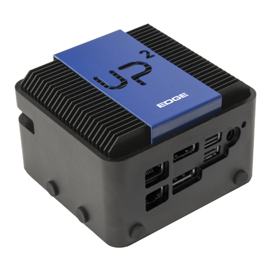
- Page 1 UPS Edge UPS Edge Gateway System Series User’s Manual ed 1...
- Page 2 AAEON assumes no liabilities resulting from errors or omissions in this document, or from the use of the information contained herein. AAEON reserves the right to make changes in the product design without notice to its users.
- Page 3 Acknowledgement All other products’ name or trademarks are properties of their respective owners. Microsoft Windows is a registered trademark of Microsoft Corp. ® Intel , Pentium , Celeron , and Xeon are registered trademarks of Intel ® ® ® ®...
- Page 4 Packing List Before setting up your product, please make sure the following items have been shipped: Item Quantity xUPS-EDxx-xxxxx-xx01 (X=0~9, A~Z, General P/N) If any of these items are missing or damaged, please contact your distributor or sales representative immediately. Preface...
- Page 5 (if any), its specifications, dimensions, jumper/connector settings/definitions, and driver installation instructions (if any), to facilitate users in setting up their product. Users may refer to the AAEON.com for the latest version of this document. Preface...
- Page 6 Safety Precautions Please read the following safety instructions carefully. It is advised that you keep this manual for future references All cautions and warnings on the device should be noted. Make sure the power source matches the power rating of the device. Position the power cord so that people cannot step on it.
- Page 7 If any of the following situations arises, please the contact our service personnel: Damaged power cord or plug Liquid intrusion to the device iii. Exposure to moisture Device is not working as expected or in a manner as described in this manual The device is dropped or damaged Any obvious signs of damage displayed on the device...
- Page 8 Il y a un risque d’explosion si la batterie est remplacée de façon incorrecte. Ne la remplacer qu’avec le même modèle ou équivalent recommandé par le constructeur. Recycler les batteries usées en accord avec les instructions du fabricant et les directives gouvernementales de recyclage. AAEON FCC ID: OHBUWSKIT1 Preface VIII...
- Page 9 China RoHS Requirements (CN) 产品中有毒有害物质或元素名称及含量 AAEON Main Board/ Daughter Board/ Backplane 有毒有害物质或元素 部件名称 铅 汞 镉 六价铬 多溴联苯 多溴二苯醚 (Pb) (Hg) (Cd) (Cr(VI)) (PBB) (PBDE) 印刷电路板 ○ ○ ○ ○ ○ ○ 及其电子组件 外部信号 ○ ○ ○ ○ ○ ○...
- Page 10 China RoHS Requirement (EN) Poisonous or Hazardous Substances or Elements in Products AAEON Main Board/ Daughter Board/ Backplane Poisonous or Hazardous Substances or Elements Hexavalent Polybrominated Polybrominated Component Lead Mercury Cadmium Chromium Biphenyls Diphenyl Ethers (Pb) (Hg) (Cd) (Cr(VI)) (PBB) (PBDE) PCB &...
-
Page 11: Table Of Contents
Table of Content Chapter 1 - Product Specifications ....................1 1.1 Product Features ....................... 2 Specifications ....................... 2 Chapter 2 – Hardware Information .....................6 System Dimensions ....................7 I/O Location......................... 8 List of Systems Connectors ..................8 Motherboard Information ..................10 List of Jumpers and Connectors................ -
Page 12: Chapter 1 - Product Specifications
Chapter 1 Chapter 1 - Product Specifications Chapter 1 – Product Specifications... -
Page 13: 1.1 Product Features
1.1 Product Features Intel® Apollo Lake SoC N33350, N4200 and E3900 Series (E3930, E3940, E3950) Onboard LPDDR4 Memory up to 8GB, eMMC Storage up to 64GB Gigabyte LAN x 2, HDMI x 1, DP x 1 USB 2.0 x 1, USB 3.0 x 3, USB 3.0 OTG x 1 ... - Page 14 Onboard Single/Dual Channel LPDDR4 Memory Type memory, up to 8GB SPI BIOS - 128Mb Flash BIOS Power Requirement 5V DC Only @6A Power Supply Type DC-In Power Consumption MAX 25W (Typical) 105 x 100 x 69,4mm (L x W x H) Dimensions (L x W) ...
- Page 15 Realtek RTL8111G-CG x 2 Ethernet HDMI I2S x 1 Audio DP x 1 USB 3.0 OTG x 1 USB 3.0 x 3 USB 2.0 x 1 Antenna x 4 Antenna Power button x 1 Power input ...
- Page 16 Bluetooth V5.0 Bluetooth SoC : Intel® Movidius™ Myriad™ X VPU 2485 AI Core Supported Frameworks :TensorFlow, Caffe Myriad- X interface: mini-PCI-e Minimum system requirements : x86_64 computer running, Ubuntu 16.04 Available, mPCI-E slot ,1GB RAM, 4GB free storage space Chapter 1 –...
-
Page 17: Chapter 2 - Hardware Information
Chapter 2 Chapter 2 – Hardware Information Chapter 2 – Hardware Information... -
Page 18: System Dimensions
System Dimensions Chapter 2 – Hardware Information... -
Page 19: I/O Location
I/O Location List of Systems Connectors Please refer to the table below to locate the I/Os represented at the point 2.2. Label Function Display Port HDMI GbLAN Network port 1 GbLAN Network port 2 Dual USB 3.0 stack Power input jack Power button USB 3.0 port Antenna connector... - Page 20 Antenna connector Antenna connector Antenna connector Chapter 2 – Hardware Information...
-
Page 21: Motherboard Information
Motherboard Information Chapter 2 – Hardware Information... - Page 22 Chapter 2 – Hardware Information...
-
Page 23: List Of Jumpers And Connectors
List of Jumpers and Connectors Label Function POWER BUTTON RESET M.2 E-KEY mini Card SATA CN10 SATA POWER CN13 USB3 OTG CN14 USB3 DUAL PORT CN15 USB3 CN16 USB panel CN17 CN18 LAN DUAL PORT CN20 HAT40 CN21 EXHAT CN22 CPLD and BIOS update CN23 DC JACK... - Page 24 2.5.1 RTC Battery (CN1) Signal 3.3V 2.5.2 Power Button (CN2) Signal PWRBTN # Chapter 2 – Hardware Information...
- Page 25 2.5.3 Reset (CN3) Signal RESET # 2.5.4 M.2 E-KEY (CN7): 802.11ac, 1x1, Bluetooth 4.2® (via M.2 2230) Signal Signal Signal 3.3V USB_D+ 3.3V USB_D- Chapter 2 – Hardware Information...
- Page 26 UART_RXD UART0_TXD UART0_CTS PCIE_C_TXP3 UART0_RTS PCIE_C_TXN3 PCIE_RXP3 PCIE_RXN3 CLK_PCIE_M2_P CLK_PCIE_M2_N Suspend Clock RESET # PCIE_M2_CLKREQ# Bluetooth Enable WAKE # Wi-Fi Enable SMBus_DAT SMBus_CLK SMBus_Alert 3.3V 3.3V Chapter 2 – Hardware Information...
- Page 27 2.5.5 Mini Card (CN8) Signal Signal Signal WAKE # 3.3V INT_SERIRQ 1.5V PCIE_MINI_CLKREQ# CLK_PCIE_MINI_N CLK_PCIE_MINI_P 3G Enable RESET # PERn0_mSATA_R+ 3.3V PERp0_mSATA_R- 1.5V I2C_CLK PETn0_mSATA_T- I2C_DAT PETp0_mSATA_T+ USB_D- USB_D+ 3.3V 3.3V mSATA_PCIe_SEL_C 1.5V 3.3V Chapter 2 – Hardware Information...
- Page 28 2.5.6 SATA (CN9) Signal Signal Signal 2.5.7 SATA (CN10) Signal Chapter 2 – Hardware Information...
- Page 29 2.5.8 USB3 OTG (CN13) Signal Signal Signal USB2_D- USB2_D+ USB3_RX- RSB3_RX+ USB3_TX- USB3_TX+ 2.5.9 USB DUAL PORT (CN14) Signal Signal Signal USB2_D1- USB2_D1+ USB3_RX1- USB3_RX1+ USB3_TX1- USB3_TX1+ USB2_D2- USB2_D2+ USB3_RX2- USB3_RX2+ USB3_TX2- USB3_TX2+ Chapter 2 – Hardware Information...
- Page 30 2.5.10 USB 13 (CN15) Signal Signal Signal USB2_D- USB2_D+ USB3_RX- USB3_RX+ USB3_TX- USB3_TX+ 2.5.11 USB Panel (CN16) Signal Signal Signal USB2_D1- USB2_D1+ USB2_D2- USB2_D2+ UART_RX UART_TX Chapter 2 – Hardware Information...
- Page 31 2.5.12 FAN (CN17) Signal Signal 2.5.13 LAN Dual Port (CN18) Signal Signal Signal LAN1_MDI0+ LAN1_MDI0- LAN1_MDI1+ LAN1_MDI1- LAN1_MDI2+ LAN1_MDI2- LAN1_MDI3+ LAN1_MDI3- R10A LAN1_ACTLED- LAN1_ACTLED+ LAN1_LINK1000# LAN1_LINK100# LAN2_MDI0+ LAN2_MDI0- LAN2_MDI1+ LAN2_MDI1- LAN2_MDI2+ LAN2_MDI2- LAN2_MDI3+ LAN2_MDI3- R10B LAN2_ACTLED- LAN2_ACTLED+ LAN2_LINK1000# Chapter 2 – Hardware Information...
- Page 32 LAN2_LINK100# 2.5.14 HAT 40 (CN20) Signal BIOS GPIO0/I2C1_SDA GPIO1 GPIO1/I2C1_SCL GPIO2 GPIO2/ADC_in1 GPIO3 GPIO15/UART_TXD GPIO16 GPIO16/UART_RXD GPIO17 GPIO3/UART_RTS/ADC_in2 GPIO4 GPIO17/I2S_BCLK GPIO18 GPIO4/ADC_in3 GPIO5 GPIO5/ADC_in4 GPIO6 GPIO18 GPIO19 Chapter 2 – Hardware Information...
- Page 33 GPIO19 GPIO20 GPIO6/SPI_1_TXD GPIO7 GPIO7/SPI_1_RXD GPIO8 GPIO20 GPIO21 GPIO8/SPI_1_CLK GPIO9 GPIO21/SPI_1_FS0 GPIO22 GPIO22/SPI_1_FS1 GPIO23 GPIO9/I2C0_SDA GPIO10 GPIO23/I2C0_SCL GPIO24 GPIO10 GPIO11 GPIO11 GPIO12 GPIO24/PWM0 GPIO25 GPIO12/PWM1 GPIO13 GPIO13/I2S_WS_SYNC GPIO14 GPIO25/UART_CTS GPIO26 GPIO14 GPIO15 GPIO26/I2S_SDI GPIO27 GPIO27/I2S_SDO GPIO28 Chapter 2 – Hardware Information...
- Page 34 2.5.15 EXHAT (CN21) Signal Signal Signal GPIO1 GPIO2 GPIO3 GPIO4 GPIO5 GPIO6 GPIO7 GPIO8 GPIO9 GPIO10 GPIO11 GPIO12 GPIO13 GPIO14 GPIO15 GPIO16 PLL_IN- PLL1_OUT- PLL1_IN+ PLL1_OUT+ INT_SERIRQ_R LPC_R_CLKOUT0 LPC_CLKRU_N LPC_R_AD3 SIO_SPI_1_TXD LPC_R_AD2 SIO_SPI_1_RXD LPC_R_AD1 SIO_SPI_1_FS0 LPC_R_AD0 SIO_SPI_1_FS1 SIO_SPI_1_CLK LPC_FRAME_R I2C_SCL3_3V3 AVS_DMIC_CLK_A1 I2C_SDA3_3V3 AVS_DMIC_CLK_B1...
- Page 35 I2C_SCL2_3V3 I2C_SDA2_3V3 AVS_DMIC_DATA_1 AVS_DMIC_DATA_2 2.5.16 CPLD and BIOS update (CN22) Signal Signal Signal JTAG_TCK JTAG_TDO 1.8V JTAG_TMS SPI_CS SPI_CLK SPI_MISO JTAG_TDI SPI_MOSI SPI_HOLD 2.5.17 CPLD and BIOS update (CN22) Signal Signal Signal Chapter 2 – Hardware Information...
- Page 36 2.5.18 HDMI Dual Port (CN24) Signal Signal Signal DDI0_TXP_DP_0 DDI0_TXN_DP_0 DDI0_TXP_DP_1 DDI0_TXN_DP_1 DDI0_TXP_DP_2 DDI0_TXN_DP_2 PORT0_CLK+ PORT0_CLK- CONFIG1 CONFIG2 DP_AUX_P DP_AUX_N DDI0_TYPE_C_HPD 3.3V DDI1_TXP_HDMI_0 DDI1_TXN_HDMI_0 DDI1_TXP_HDMI_1 DDI1_TXN_HDMI_1 DDI1_TXP_HDMI_2 DDI1_TXN_HDMI_2 DDI1_CLK+_HDMI DDI1_CLK-_HDMI HDMI1_CEC_D DDC_CLK DDC_DATA DDI1_TYPE_C_HPD Chapter 2 – Hardware Information...
-
Page 37: Chapter 3 - Drivers Installation
Chapter 3 Chapter 3 - Drivers Installation Chapter 3 – Drivers Installation... -
Page 38: Driver Download And Installation
Driver Download and Installation Please follow the steps for driver downloading and installation. Step 0 – Basic setup of the system and accessories Power adapter (5V/6A DC) is well connected with system and power outlet Connect HDMI cable in type A male connector. make sure it's well connected with system and display Connect Keyboard &... -
Page 39: Lora® Stack Setup And Test (Only For Lora Version Running Linux)
OpenVino installation Make sure the bios is updated to latest stable version: https://downloads.up-community.org/ to get the bios https://wiki.up-community.org/Bios_Update to get the procedure Install Ubuntu or Ubilinux following the instructions here: For Ublinux: https://wiki.up-community.org/Ubilinux For Ubuntu: https://wiki.up-community.org/Ubuntu The gateway is pre-validated with OpenVINO development kit, for more informations check https://software.intel.com/en-us/openvino-toolkit Get the open source AI stack Hardware Abstraction Layer from... - Page 40 #2 Extract OPENVINO on Downloads #3 Type: cd ~/Downloads/l_openvino_toolkit_p_2018.5.445/ #4 Type: sudo -E ./install_cv_sdk_dependencies.sh #5 Type: sudo ./install_GUI.sh #6 Accept license agreement and click Next Chapter 3 – Drivers Installation...
- Page 41 #7 click Next #8 click install Chapter 3 – Drivers Installation...
- Page 42 #9 Finish install Build Sample #1 Type: source /opt/intel/computer_vision_sdk/bin/setupvars.sh #2 Type: cd/opt/intel/computer_vision_sdk/deployment_tools/model_optimizer/install_ prerequisites M. #3 Type: sudo ./install_prerequisites.sh Chapter 3 – Drivers Installation...
- Page 43 #4 Type: cd /opt/intel/computer_vision_sdk/deployment_tools/demo O. #5 Type: ./demo_squeezenet_download_convert_run.sh #6 Type: ./demo_security_barrier_camera.sh Chapter 3 – Drivers Installation...
- Page 44 Q. #7 Type: cd ~/inference_engine_samples_build/intel64/Release/ Run demo face detection by use MYRIAD #1 Type: cd ~/inference_engine_samples_build/intel64/Release/ #2 Type: sudo su #3 Type: source /opt/intel/computer_vision_sdk/bin/setupvars.sh #4 Type: ./interactive_face_detection_demo -i "cam" -m /opt/intel/computer_vision_sdk/deployment_tools/intel_models/face- detection-adas-0001/FP16/face-detection-adas-0001.xml -d MYRIAD Run demo face detection by use CPU #1 Type: cd ~/inference_engine_samples_build/intel64/Release/ W.
- Page 45 10. Run demo face detection by use HDDL ***#1~#3 Just do it once*** EE. #1 Type: sudo gedit /opt/intel/computer_vision_sdk/inference_engine/external/hddl/config/h ddl_autoboot.config FF. #2 edit total_device_num ,according to your myriadx device number to edit GG. #3 Type: reboot Chapter 3 – Drivers Installation...
- Page 46 HH. #4 Type: cd ~/inference_engine_samples_build/intel64/Release/ #5 Type: sudo su #6 Type: source /opt/intel/computer_vision_sdk/bin/setupvars.sh KK. #7 Type: ./interactive_face_detection_demo -i "cam" -m /opt/intel/computer_vision_sdk/deployment_tools/intel_models/face- detection-adas-0001/FP16/face-detection-adas-0001.xml -d HDDL Build Reset LL. #1 Type: cd /opt/intel/computer_vision_sdk/inference_engine/external/hddl/hddl- bsl/ Chapter 3 – Drivers Installation...
- Page 47 MM. #2 Type: sudo apt-get install libudev1 NN. #3 Type: sudo apt-get install libudev-dev libjson-c-dev OO. #4 Type: sudo su PP. #6 Type: mkdir build QQ. #7 Type: cd build RR. #8 Type: make –j SS. #9 Type: make install Chapter 3 –...
- Page 48 12. Run Reset TT. #1 Type: cd /opt/intel/computer_vision_sdk_2018.5.445/deployment_tools/inference_engi ne/external/hddl/hddl-bsl/build/src UU. #2 Type: sudo ./bsl_reset -i 224 *** 11100XXX : XXX is device 0-8 ,if device 0 , you should transform (11100000)2 to (224)10 VV. Completed Chapter 3 – Drivers Installation...
Need help?
Do you have a question about the UPS Edge Series and is the answer not in the manual?
Questions and answers