Table of Contents
Advertisement
Quick Links
A l l t e s t I n s t r u me n t s , I n c .
5 0 0 C e n t r a l A v e .
F a r mi n g d a l e , N J 0 7 7 2 7
P : ( 7 3 2 ) 9 1 9 - 3 3 3 9
F : ( 7 3 2 ) 9 1 9 - 3 3 3 2
a l l t e s t . n e t
s s a l e s @ a l l t e s t . n e t
T h e t e s t & me a s u r e me n t
e q u i p me n t y o u n e e d a t
t h e p r i c e y o u w a n t .
A l l t e s t c a r r i e s t h e w o r l d ' s l a r g e s t s e l e c t i o n o f
u s e d / r e f u r b i s h e d b e n c h t o p t e s t & me a s u r e me n t
e q u i p me n t a t 5 0 % t h e p r i c e o f n e w .
O O u r e q u i p me n t i s g u a r a n t e e d w o r k i n g , w a r r a n t i e d , a n d
a v a i l a b l e w i t h c e r t i f i e d c a l i b r a t i o n f r o m o u r i n - h o u s e s t a f f
o f t e c h n i c i a n s a n d e n g i n e e r s .
• 1 0 + f u l l t i me t e c h n i c i a n s w i t h o v e r 1 5 0 y e a r s o f
s p e c i a l i z a t i o n
• 9 0 d a y w a r r a n t y & 5 d a y r i g h t o f r e t u r n o n a l l
e q u i p me n t
• • 1 - 3 y e a r w a r r a n t i e s f o r n e w a n d
p r e mi u m- r e f u r b i s h e d e q u i p me n t
• E v e r y u n i t t e s t e d t o O E M s p e c i f i c a t i o n s
• S a t i s f a c t i o n g u a r a n t e e d
Y o u h a v e p l a n s , w e w i l l h e l p y o u a c h i e v e t h e m.
A n y p r o j e c t . A n y b u d g e t .
t
G e t a q u o t e t o d a y !
C C a l l ( 7 3 2 ) 9 1 9 - 3 3 3 9 o r e ma i l s a l e s @a l l t e s t . n e t .
Advertisement
Table of Contents

Related Manuals for Rohde & Schwarz AM 300


Summary of Contents for Rohde & Schwarz AM 300
- Page 1 T h e t e s t & me a s u r e me n t e q u i p me n t y o u n e e d a t t h e p r i c e y o u w a n t . A l l t e s t I n s t r u me n t s , I n c .
- Page 2 02/2005...
- Page 3 Copyright R&S AM300 Copyright Copyright © Copyright 2005 ROHDE & SCHWARZ GmbH & Co. KG Test and Measurement Division Mühldorfstraße 15 81671 München, Germany edition 02/2005 Printed in Germany. Printed on FFC bleached paper. Subject to alterations, Errors excepted. Reprints, also in extracts, are only allowed with written permission of the manufacturer. All rights reserved.
-
Page 4: Chapter Overview
R&S AM300 Chapter Overview Chapter Overview General Content of the Manual for R&S AM300 Data Sheet Safety Instructions Certificate of Quality EC Certificate of Conformity Customer Support List of Rohde & Schwarz Offices Chapter 1 Introduction Chapter 2 Control Elements Chapter 3 Putting the R&S AM300 into Operation Chapter 4... -
Page 5: Content Of The Manual
Content of the Manual R&S AM300 Content of the Manual Operating Manual Introduction This operating manual provides information about: Technical characteristics of the instrument Putting into operation Basic operating procedures and control elements Operation via menus Installation and configuration of PC software Putting into operation of remote control By way of an introduction, a typical R&S AM300 measurement is described. -
Page 6: Table Of Contents
R&S AM300 Table of Contents Table of Contents Chapter Overview ..........................0-3 Content of the Manual........................0-4 Operating Manual ........................0-4 Table of Contents ..........................0-5 Data Sheet ............................0-10 Channels..........................0-10 Waveform..........................0-10 Frequency..........................0-10 Output Parameters ........................0-11 Spectral Purity (Sine)....................... -
Page 7: Table Of Contents
Table of Contents R&S AM300 3.4 Switching On the R&S AM300 ....................3-40 3.5 Function Test ......................... 3-41 3.6 EMC ............................3-41 3.7 Connecting an External Keyboard..................3-42 Getting Started .................... 4-43 4.1 Amplitude and Frequency Settings ..................4-43 Manual Operating Concept ................ 5-45 5.1 Making Entries from the Keypad.................. - Page 8 R&S AM300 Table of Contents Working with the R&S AM300 ..............6-68 6.1 Factory Default Settings ....................... 6-68 6.2 Arbitrary and Function Generator..................6-70 6.2.1 Configuring Output Signal CH1 (Menu CH1)............... 6-71 6.2.1.1 Selecting a Waveform ................. 6-72 6.2.1.2 Setting the Frequency of the Current Waveform......... 6-75 6.2.1.3 Setting the Amplitude of the Current Waveform..........
- Page 9 Table of Contents R&S AM300 6.2.4.2 Setting the Trigger Delay................6-159 6.2.4.3 Selecting the Active Trigger Edge ............. 6-159 6.2.4.4 Setting the Internal Trigger Generator Frequency ........6-160 6.2.4.5 Setting Gate/Burst Operating Mode ............6-161 6.2.4.5.1 Selecting the Gate Function ..............6-163 6.2.4.5.2 Setting the Gate Length ................
- Page 10 R&S AM300 Data Sheet 6.3.6.1 Displaying Module Data................6-216 6.3.6.2 Displaying Instrument Statistics ..............6-216 6.3.6.3 Displaying System Messages ..............6-217 Remote Control/PC Software R&S AM300-K1 ........7-219 7.1 Applications of PC Software....................7-219 7.2 Installation and Configuration.................... 7-219 7.2.1 Installing the PC Software..................7-219 7.2.1.1 Installing the Program................
-
Page 11: Data Sheet
Data Sheet R&S AM300 Data Sheet As a highly innovative company we seek to ensure that our products Note constantly undergo further development. For updates on newly added applications product characteristics please visit website http://www.smart.rohde-schwarz.com. Channels Number of channels Phase Setting range -180°... -
Page 12: Output Parameters
R&S AM300 Data Sheet Output Parameters (50 Ω) Output voltage Setting range 1 mV to 10 V (V at AM: 1 mV to 5 V Resolution 0.1 mV (4 digits) Accuracy ± 2 % Frequency response (referenced to 10 kHz sine) 10 µHz ≤... -
Page 13: Output Characteristic
Data Sheet R&S AM300 Period 70 ns to 9999 s Pulse width 20 ns to 9999 s Rise time < 10ns Overshoot < 5 % Ramp/triangle Symmetry 0 % to 100 % ± 0.1 % (f < 10 kHz) Linearity Exponential Type rising or falling... -
Page 14: Modulation 1)
R&S AM300 Data Sheet Modulation AM, FM, ϕM, FSK, PSK Modulation modes Carrier waveforms sine, triangle, ramp, square, exponential, pulse and arbitrary Modulation waveforms sine, square, triangle, ramp, exponential, noise Modulation frequency 10 mHz to 100 kHz Modulation depth 0 to 100 % resolution 0.1 % Source... -
Page 15: Gate/Burst
Data Sheet R&S AM300 Gate/Burst Waveforms sine, triangle, ramp, square, exponential and arbitrary Gate settings block end; sample & hold, burst Number of periods per burst 1 to 65535 Start phase -180° to +180° Gate length (internal) 100 ns to 9999 s Gate source internal, external Sweep... -
Page 16: Reference
R&S AM300 Data Sheet Impedance 50 Ω Sources comparator, phase accumulators, markers, trigger Reference Reference oscillator (internal) Frequency 10 MHz Stability < 1 ppm Aging < 1 ppm/year Reference input Frequency 10 MHz, 5 MHz, 2 MHz Frequency deviation < 5 * 10 Input voltage 0.5 V to 2 V (50 Ω) Input impedance... -
Page 17: General Data
Data Sheet R&S AM300 General Data Display Type 5.4” active colour TFT display Number of points 320 x 240 Memory locations Device settings Ambient conditions Operating temperature range meets DIN EN 60068-2-1/2 +5° C +45° C Storage temperature range -20° C +70°... -
Page 18: Safety Instructions
R&S AM300 Safety Instructions Safety Instructions This unit has been designed and tested in accordance with the EC Certificate Note of Conformity and has left the manufacturer’s plant in a condition fully complying with safety standards. To maintain this condition and to ensure safe operation, the user must observe all instructions and warnings given in this operating manual. - Page 19 Safety Instructions R&S AM300 Safety The unit may be used only in the operating conditions and positions specified instructions by the manufacturer. Unless otherwise agreed, the following applies to R&S products: IP degree of protection 2X, pollution severity 2 overvoltage category 2, only for indoor use, altitude max.
- Page 20 R&S AM300 Safety Instructions Lithium batteries must not be exposed to high temperatures or fire. Keep batteries away from children. If the battery is replaced improperly, there is danger of explosion. Only replace the battery by R&S type (see spare part list). Lithium batteries are suitable for environmentally-friendly disposal or specialized recycling.
-
Page 21: Certificate Of Quality
Certificate of Quality R&S AM300 Certificate of Quality Certificate of Dear Customer, quality You have decided to buy a Rohde & Schwarz product. You are thus assured of receiving a product that is manufactured using the most modern methods available. This product was developed, manufactured and tested in compliance with our quality management system standards. -
Page 22: Ec Certificate Of Conformity
R&S AM300 EC Certificate of Conformity EC Certificate of Conformity EC Certificate of Conformity Certificate No.: 2003-39 This is to certify that: Equipment type Stock No. Designation AM300 1147.1498.03 Arbitrary and function generator with two channels complies with the provisions of the Directive of the Council of the European Union on the approximation of the laws of the Member States relating to electrical equipment for use within defined voltage limits (73/23/EEC revised by 93/68/EEC) -
Page 23: Customer Support
Customer Support R&S AM300 Customer Support Technical support – For quick, expert help with any Rohde & Schwarz equipment, contact one of where and when you our Customer Support Centers. A team of highly qualified engineers provides need it telephone support and will work with you to find a solution to your query on any aspect of the operation, programming or applications of Rohde &... - Page 24 R&S AM300 List of Rohde & Schwarz Offices List of Rohde & Schwarz Offices HEADQUARTERS Phone E-Mail Germany Rohde & Schwarz GmbH & Co. KG +49 (89) 4129-0 Mühldorfstraße 15 · D-81671 München +49 (89) 4129-12164 Postfach 801469 · D-81614 München PLANTS Rohde &...
- Page 25 List of Rohde & Schwarz Offices R&S AM300 Zweigniederlassung Nord, +49 (40) 63 29 00-0 Geschäftsstelle Hamburg +49 (40) 630 78 70 Steilshooper Alle 47 · D-22309 Hamburg Postfach 60 22 40 · D-22232 Hamburg Zweigniederlassung Mitte, +49 (2203) 807-0 Geschäftsstelle Köln +49 (2203) 807-650 Niederkasseler Straße 33 ·...
-
Page 26: List Of Rohde & Schwarz Offices
R&S AM300 List of Rohde & Schwarz Offices Brasil ROHDE & SCHWARZ DO BRASIL LTDA. +55 (11) 56 44 86 11 (general) Av. Alfredo Egidio de Souza Aranha, 177, 1° +55 (11) 56 44 86 25 (sales) andar - Santo Amaro +55 (11) 56 44 86 36 04726-170 Sao Paulo –... - Page 27 List of Rohde & Schwarz Offices R&S AM300 Cyprus HINIS TELECAST LTD. +357 (24) 42 51 78 Agiou Thoma 18 +357 (24) 42 46 21 Kiti hinis@logos.cy.net Larnaca 7550 Czech Republic ROHDE & SCHWARZ - Praha s.r.o. +420 (2) 24 31 12 32 Hadovka Office Park +420 (2) 24 31 70 43 Evropská...
- Page 28 R&S AM300 List of Rohde & Schwarz Offices Germany Zweigniederlassung Büro Bonn +49 (228) 918 90-0 Josef-Wirmer-Straße 1-3 · D-53123 Bonn +49 (228) 25 50 87 Postfach 140264 · D-53057 Bonn info.rsv@rohde-schwarz.com Germany Zweigniederlassung Nord, Geschäftsstelle +49 (40) 63 29 00-0 Hamburg +49 (40) 630 78 70 Steilshooper Alle 47 ·...
- Page 29 List of Rohde & Schwarz Offices R&S AM300 India ROHDE & SCHWARZ India Pvt. Ltd. +91 (22) 26 30 18 10 RS India Mumbai Office +91 (22) 26 73 20 81 B-603, Remi Bizcourt, Shah Industrial rsindiam@rsnl.net Estate, Off Veera Desai Road Mumbai - 400 058 Indonesia PT ROHDE &...
- Page 30 R&S AM300 List of Rohde & Schwarz Offices Kenya Excel Enterprises Ltd +254 (2) 55 80 88 Dunga Road +254 (2) 54 46 79 P.O.Box 42 788 Nairobi Korea ROHDE & SCHWARZ Korea Ltd. +82 (2) 3485 1900 83-29 Nonhyun-Dong, Kangnam-Ku +82 (2) 3485 1900 Seoul 135-010 sales@rskor.rohde-schwarz.com...
- Page 31 List of Rohde & Schwarz Offices R&S AM300 Netherlands ROHDE & SCHWARZ NEDERLAND B.V. +31 (30) 600 17 00 Perkinsbaan 1 +31 (30) 600 17 99 3439 ND Nieuwegein info@rsn.rohde-schwarz.com New Zealand Nichecom +64 (4) 232 32 33 1 Lincoln Ave. +64 (4) 232 32 30 Tawa, Wellington rob@nichecom.co.nz...
- Page 32 R&S AM300 List of Rohde & Schwarz Offices Serbia-Montenegro Representative Office Belgrade +381 (11) 305 50 25 Tose Jovanovica 7 +381 (11) 305 50 24 11030 Beograd Singapore Rohde & Schwarz +65 (6) 846 1872 Regional Headquarters Singapore Pte. Ltd. +65 (6) 846 1252 1 Kaki Bukit View rsca@rssg.rohde-schwarz.com...
- Page 33 List of Rohde & Schwarz Offices R&S AM300 Thailand Schmidt Electronics (Thailand) Ltd. +66 (2) 643 13 30 to 39 63 Government Housing Bank Bldg. +66 (2) 643 13 40 Tower II, 19th floor, Rama 9 Rd. kamthoninthuyot@schmidtthailand.com Huaykwang, Bangkapi Bangkok 10320 Trinidad &Tobago siehe Mexico...
- Page 34 R&S AM300 List of Rohde & Schwarz Offices Venezuela Equilab Telecom C.A. +58 (2) 12 34 46 26 Centro Seguros La Paz +58 (2) 122 39 52 05 Piso 6, Local E-61 r_ramirez@equilabtelecom.com Ava. Francisco de Miranda Boleita, Caracas 1070 Venezuela Representaciones Bopic S.A.
-
Page 35: Introduction
Application Range of the R&S AM300 R&S AM300 Introduction This chapter Chapter 1 describes the use of the R&S AM300, provides information on functions and supplies tips regarding storage and transportation procedures. Warranty conditions are also explained. Further Chapter 2 contains an overview of R&S AM300 control elements, indicators, information etc. -
Page 36: Supplied Accessories
R&S AM300 Supplied Accessories Supplied Accessories Content 1 power cord Europe 1 manual German/English 1 CD (Content: operating manual German/English, data sheet German/English PC software R&S AM300-K1, Acrobat Reader™) If you wish to generate user-defined (arbitrary) waveforms on a PC, you need Note the PC software known as Waveform Composer R&S AM300-K2 (order number 1147.2013.02). -
Page 37: Control Elements
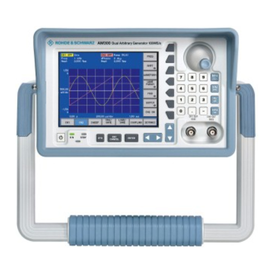
Front View R&S AM300 Control Elements Front View ON/STANDBY switch Signal output CH1 (BNC connector) ON/STANDBY indicator Signal output CH2 (BNC connector) SYS key Unit keys ESC/CANCEL key Rotary knob ENTER key Numerical keys Cursor keys 3 / 4 Function keys Screen Cursor keys 6 / 5 E-1007.9922.12... -
Page 38: Rear View
R&S AM300 Rear View Rear View Output for external filter signal of AC line switch channel CH2 Connector for external monitor Input for external filter signal of Connector for external keyboard channel CH2 Input for external trigger/gate signal Input for external reference (10 MHz, 5 MHz, 2 MHz) Output for sync signal of channel CH2 Output for internal/external reference... -
Page 39: Putting The R&S Am300 Into Operation
Unpacking the R&S AM300 R&S AM300 Putting the R&S AM300 into Operation This chapter Chapter 3 describes how to put the R&S AM300 into operation. Further Chapter 2 contains an overview of the R&S AM300‘s control elements, indicators, etc. information Chapter 4, “Getting started”, takes you step-by-step through a number of simple measurements. - Page 40 R&S AM300 Setting up the Instrument Setting the handle Place the thumb and two fingers around the side-mounted setting lever and loosen it with a turning action. Slide the handle lengthwise while twisting it radially in steps of about 12°. Close the setting lever by pressing on the outer surface.
-
Page 41: Connecting The R&S Am300 To The Ac Line
Connecting the R&S AM300 to the AC Line R&S AM300 Connecting the R&S AM300 to the AC Line The R&S AM300 meets the requirements for Safety Class I to DIN EN 61010- Caution 1/IEC 61010-1, e. g. all metal parts that can be touched or accessed without removing the enclosure are connected to the protective ground of the power supply network. -
Page 42: Function Test
R&S AM300 Function Test Function Test When performing service procedures, follow the requirements of VDE 0701. Caution Only properly qualified technicians are allowed to repair the R&S AM300. The instrument does not contain any parts the operator can repair. Function test After the R&S AM300 has been switched on ( 3-40), the green LED ON [2] on the instrument’s front panel comes on. -
Page 43: Connecting An External Keyboard
Connecting an External Keyboard R&S AM300 Connecting an External Keyboard Only connect the keyboard when the R&S AM300 is off or in the STANDBY Caution mode, otherwise malfunctions may occur at a later date. You can connect an external PC keyboard via the 6-pin PS/2 KEYB connector [25] on the R&S AM300’s rear panel. -
Page 44: Getting Started
R&S AM300 Amplitude and Frequency Settings Getting Started This chapter Chapter 4 uses a number of simple settings to illustrate how to operate the R&S AM300. For the following example, the initial setting for instrument is the default setting (factory). This is set in the menu PRESET ( 6-191). - Page 45 Amplitude and Frequency Settings R&S AM300 Set signal amplitude V = 5 V. • Stay in the menu. • Press the key. • Press the key. • Use the numeric keys to enter the value . Finish the entry with the key.
-
Page 46: Manual Operating Concept
R&S AM300 Making Entries from the Keypad Manual Operating Concept This chapter Chapter 5 contains an overview of the R&S AM300's basic manual operating concept. This includes a description of the keypad, the screen layout, menu operation and how to set parameters. There is an overview of the menus and functions at the end of this chapter. -
Page 47: Rotary Knob
Making Entries from the Keypad R&S AM300 In the case of all other entries, the unit keys assume the same function as the Note Enter key ( 5-47). 5.1.3 Rotary Knob Function As well as the numerical keys and the cursor keys, the rotary knob is also used to set parameters. -
Page 48: Action Keys
R&S AM300 Making Entries from the Keypad 5.1.6 Action Keys Function The action keys are for terminating menu-guided settings. − This key is for closing the entry field or selection field after data has been entered. The new value is set on the R&S AM300. Note: Pressing a unit key will also terminate the entry of setting data. -
Page 49: Screen Display
Screen Display R&S AM300 Screen Display Introduction The screen [14] provides on-going information about events and the parameters associated with the selected measurement functions. The display mode for the measurement results, the lettering of the function keys and the type of menu all depend on the current settings. The screen is divided into three areas: Screen layout Diagram area... -
Page 50: Diagram Area
R&S AM300 Screen Display 5.2.1 Diagram Area Display window The display window contains: Curve diagram (b) with waveforms of channels CH1 (g) and CH2 (f) Parameter field with settings of channels CH1 (c) and CH2 (d) Selection fields and entry fields that come up on the screen (a) Error messages that come up on the screen (e) Curve diagram A 8 x 6 grid is superimposed on the diagram area to make it easier to analyze... -
Page 51: Function Area
Screen Display R&S AM300 5.2.3 Function Area Displaying the When a menu is selected, the associated instrument functions are displayed current assignment in the function area. for the function keys The displayed instrument functions are assigned to the seven function keys down the right-hand side of the screen. -
Page 52: Calling And Changing Menus
R&S AM300 Calling and Changing Menus Calling and Changing Menus Introduction Operating the R&S AM300 is menu-guided. All the menus used to set the measurement parameters and measurement functions are displayed in the menu area. The instrument functions associated with any menu you select are displayed in the function area. - Page 53 Calling and Changing Menus R&S AM300 Calling/quitting Press the function key in the menu. submenus The SWEEP FREQ submenu opens and the new functions are assigned to the function keys [13]. Press the function key in the submenu. The submenu is closed and the previous functions remain assigned to the function keys [13].
-
Page 54: Setting Parameters
R&S AM300 Setting Parameters Setting Parameters There is a choice Parameters can be set in a number of ways: of methods Direct selection of an instrument function (function key) Toggling of a setting Selecting settings from selection fields Entering numerical parameters in entry fields The numerical keys [12], the unit keys [10], the rotary knob [11], the cursor keys [6, 7] and the action keys [4, 5] can all be used to select and enter instrument parameters. -
Page 55: Selecting Settings
Setting Parameters R&S AM300 5.4.3 Selecting Settings Introduction When you select a menu, a number of instrument functions are displayed in the function area. If certain function keys are then pressed, a selection field is displayed in the diagram area. You can then choose and activate any of the settings offered for selection. -
Page 56: Entering Numerical Parameters
R&S AM300 Setting Parameters 5.4.4 Entering Numerical Parameters Introduction When you select a menu, a number of instrument functions will be displayed in the function area. If you press certain function keys, an entry field will be displayed in the diagram area. The function key you select is highlighted. - Page 57 Setting Parameters R&S AM300 Terminating a) Press a unit key [10], e. g. MHz, to terminate the entry. entries The R&S AM300 sets the value that has been set numerically using the new unit. The entry window is closed. b) Press the ENTER key [5] to terminate the entry. The R&S AM300 sets the value that has been set numerically, but with the old unit.
-
Page 58: Entry Using The Cursor Keys And The Rotary Knob
R&S AM300 Setting Parameters 5.4.4.2 Entry using the Cursor Keys and the Rotary Knob e. g.: Press the function key in the menu. Setting the signal amplitude Press the function key in the subenu. 6-77) An entry field containing the current setting is displayed. Entering Using the cursor keys 3 and 4 [6], position the cursor on a decimal a new value,... - Page 59 Setting Parameters R&S AM300 Terminating a) Press the ENTER key [5] to terminate the entry. entries The R&S AM300 sets the value that has been set numerically but with the old unit. The entry window is closed. Note: If a parameter is unitless or always has the same unit, you can terminate the entry with the ENTER key or one of the unit keys.
-
Page 60: Overview Of All Menus And Functions
R&S AM300 Overview of all Menus and Functions Overview of all Menus and Functions 5.5.1 Arbitrary and Function Generator 5.5.1.1 CH1 Menu (CH2) Function key assignment Set the frequency of the current waveform 6-75) Open submenu: Set the amplitude of the current waveform Sine Triangle Exponential... - Page 61 Overview of all Menus and Functions R&S AM300 Open submenu: Modulate waveform Exit submenu Open submenu: Set amplitude modulation Exit submenu Set modulation frequency 6-116) Set modulation depth 6-116) Select modulation signal 6-115) Switch modulation on/off 6-117) Open submenu: Set frequency modulation Exit submenu Set modulation frequency 6-120)
- Page 62 R&S AM300 Overview of all Menus and Functions Open submenu: Set phase shift keying Exit submenu Set modulation frequency 6-131) Set modulation period 6-131) Set phase shift 6-132) Select modulation source 6-131) Select modulation signal polarity 6-132) Switch modulation on/off 6-133) Open submenu: Configure signal output...
-
Page 63: Sweep Menu
Overview of all Menus and Functions R&S AM300 5.5.1.2 SWEEP Menu Function key assignment Open submenu: Set the sweep frequency range 6-147) Exit submenu Etering the center frequency 6-148) Etering the frequency range 6-148) Etering the starting frequency 6-149) Etering the stopping frequency 6-149) Select trigger mode 6-150) -
Page 64: Trig/Gate Menu
R&S AM300 Overview of all Menus and Functions 5.5.1.3 TRIG/GATE Menu Function key assignment Select trigger mode 6-157) Set trigger delay 6-159) Select active trigger edge 6-159) Set internal trigger generator frequency 6-160) Set internal trigger generator period 6-160) Open submenu: Set Gate/Burst operating mode Exit submenu Select gate function... - Page 65 Overview of all Menus and Functions R&S AM300 5.5.1.4 LOAD/SAVE Menu Function key assignment Load waveform from the internal flash memory into channel CH1 6-170) Load waveform from the internal flash memory into channel CH2 6-170) Load waveform from the external USB stick into channel CH1 6-171) Load waveform from the external USB stick into channel CH2 6-171)
- Page 66 R&S AM300 Overview of all Menus and Functions 5.5.1.6 DISPLAY Menu Function key assignment Open submenu: Display waveforms Exit submenu Switch channel CH1 display on/off 6-179) Switch channel CH2 display on/off 6-179) Switch on display of voltage values from CH1 and CH2 6-180) Open submenu: Scaling of diagram area...
- Page 67 Overview of all Menus and Functions R&S AM300 5.5.2 SYSTEM Functions 5.5.2.1 PRESET Menu Function key assignment Calls an instrument default setting 6-192) Selects an instrument default setting 6-192) 5.5.2.2 STATUS Menu Function key assignment Display of waveform settings in channel CH1 6-194) Display of waveform settings in channel CH2 6-195)
- Page 68 R&S AM300 Overview of all Menus and Functions 5.5.2.4 CONFIG Menu Function key assignment Sets the date and time 6-205) Selects an internal or external reference source 6-207) Configures the instrument interfaces 6-209) Sets the screen saver mode 6-211) Selects an internal or external monitor 6-213) 5.5.2.5 SERVICE Menu...
-
Page 69: Working With The R&S Am300
Factory Default Settings R&S AM300 Working with the R&S AM300 In this chapter Chapter 6 fully explains all the functions of the arbitrary and function generator, and the application of these functions. The menus are described in the same sequence as the procedure for configuring and producing an output signal: R&S AM300 default settings Setting signal parameters... - Page 70 R&S AM300 Factory Default Settings Sync polarity (SYNC POLARITY) Normal Normal Sync output (SYNC ON) Amplitude Modulation signal (AM WAVEFORM) Sine Sine modulation Modulation frequency (AM FREQ) 100 Hz Modulation depth (AM DEPTH) 50 % 50 % AM status (AM ON) Frequency Modulation signal (FM WAVEFORM) Sine...
-
Page 71: Arbitrary And Function Generator
Arbitrary and Function Generator R&S AM300 Arbitrary and Function Generator Introduction The arbitrary and function generator is capable of generating multiple standard and user-defined waveforms with variable parameters. These waveforms can be modulated, swept, synchronized and gated. User interface After switching on the R&S AM300, the user interface of the arbitrary and function generator is active. -
Page 72: Configuring Output Signal Ch1 (Menu Ch1)
R&S AM300 Arbitrary and Function Generator 6.2.1 Configuring Output Signal CH1 (Menu CH1) What the settings The CH1 and CH2 menus can be used to enter all the setting options needed are for to output a user-configurable standard waveform or a user-defined (arbitrary) waveform at output CH1 or CH2 respectively. -
Page 73: Selecting A Waveform
Arbitrary and Function Generator R&S AM300 6.2.1.1 Selecting a Waveform Application The R&S AM300 can generate the following waveforms: Standard waveform Sine Triangle Ramp Square Exponential Noise Square Low Jitter Pulse User-defined waveform Arbitrary Waveform The two channels on the R&S AM300 can operate in two different combinations in configurations. - Page 74 R&S AM300 Arbitrary and Function Generator Application range of Square the Square/Square During signal generation in function generator mode (standard waveforms, Low Jitter e.g. sine) the amplitude information is read out from the waveform memory waveforms using a fixed sample rate of 100 MHz. This gives a fixed time grid of 10 ns for signal changes.
- Page 75 Arbitrary and Function Generator R&S AM300 Selecting a In the menu press the function key. waveform A selection field with default settings is displayed. The default is "Sine". Use the rotary knob [11] to select a waveform, e.g. "Square". Press the ENTER [5] key to close the selection field. The new setting is stored and the waveform is displayed in the diagram area with at least one period.
-
Page 76: Setting The Frequency Of The Current Waveform
R&S AM300 Arbitrary and Function Generator 6.2.1.2 Setting the Frequency of the Current Waveform Application The frequency for the currently applicable waveform can be set in relation to a channel ( 6-72). When frequency coupling is on ( 6-175) the frequency setting also applies to the other channel. - Page 77 Arbitrary and Function Generator R&S AM300 Frequency display The new setting is stored and displayed in the diagram area. The divisions of the time axis (grid lines) change in accordance with the frequency setting. The currently applicable signal frequency is displayed in the parameter field below the channel name CH1 or CH2, e.g.
-
Page 78: Setting The Amplitude Of The Current Waveform
R&S AM300 Arbitrary and Function Generator 6.2.1.3 Setting the Amplitude of the Current Waveform What the settings You can use the AMPT submenu to set the signal amplitude, DC component are for and output voltage limits of the currently applicable waveform. The signal amplitude refers to the unmodulated fundamental. -
Page 79: Sine Waveform
Arbitrary and Function Generator R&S AM300 6.2.1.3.1 SINE Waveform Application You can set the following amplitude parameters for the Sine waveform: UPPER LIMIT Vpp (Vrms, dBm) DC OFFSET LOWER LIMIT Selecting Select the Sine waveform ( 6-72). the AMPT In the menu press the function key. - Page 80 R&S AM300 Arbitrary and Function Generator Setting the Signal Amplitude Application The signal amplitude can be entered in different forms: - as a peak-to-peak value in volts - as an rms value in volts - as a power value in decibels Setting the signal In the submenu press the...
- Page 81 Arbitrary and Function Generator R&S AM300 Setting the signal In the submenu press the function key. amplitude as an rms value V An entry field containing the current setting is displayed. Enter a new value ( 5-55). The value range for the rms value V results from the conditions for the peak-to-peak value V and the DC offset.
- Page 82 R&S AM300 Arbitrary and Function Generator Setting the DC Component Application The DC OFFSET is a DC component that is added to the signal amplitude. When this is done the sum of the DC offset and the peak value must not exceed the maximum permissible range ( 6-79).
- Page 83 Arbitrary and Function Generator R&S AM300 Display The new setting is stored and then displayed in the diagram area. The zero- symmetrical waveform is raised by the DC offset, e.g. 1.5 V. DC OFFSET E-1007.9922.12 6-82 Operating manual, 02/2005...
- Page 84 R&S AM300 Arbitrary and Function Generator Setting the Limitation of the Output Voltage Before setting the limit values you need to lower the currently applicable Note output voltage of the channels so that they are within the desired limit values. Application The maximum voltage at the output of the R&S AM300 can be limited.
- Page 85 Arbitrary and Function Generator R&S AM300 Error message if a If you wish to set an output voltage that would be outside one of the limit parameter is values, you receive a message containing the currently allowable setting exceeded , e.g.: range UPPER LIMIT = +5 V, DC OFFSET = 1.5 V, new V = 8 V...
-
Page 86: Triangle Waveform
R&S AM300 Arbitrary and Function Generator 6.2.1.3.2 TRIANGLE Waveform Application You can set the following amplitude parameters for the Triangle waveform: UPPER LIMIT DC OFFSET LOWER LIMIT Selecting Select the Triangle waveform ( 6-72). the AMPT In the menu press the function key. - Page 87 Arbitrary and Function Generator R&S AM300 Setting the Signal Amplitude Application The signal amplitude can be entered in different forms: V+, V- - as a positive and negative peak value relative to the zero line on the measurement diagram - as a peak-to-peak value ( 6-79) Note: When the amplitude parameters change the other parameters associated with them are computed and synchronized.
-
Page 88: Ramp Waveform
R&S AM300 Arbitrary and Function Generator Restricting the The entry range for the signal amplitude can be restricted by the value range following parameters: DC component DC OFFSET ( 6-81) Limitation of output voltage LOWER/UPPER LIMIT 6-83) 6.2.1.3.3 RAMP Waveform Application You can set the following amplitude parameters for the Ramp waveform: UPPER LIMIT... -
Page 89: Square And Square Low Jitter Waveforms
Arbitrary and Function Generator R&S AM300 6.2.1.3.4 SQUARE and SQUARE LOW JITTER Waveforms Application You can set the following amplitude parameters for the Square and Square Low Jitter waveforms: UPPER LIMIT DC OFFSET LOWER LIMIT Select the Square or Square Low Jitter waveform ( 6-72). -
Page 90: Exponential Waveform
R&S AM300 Arbitrary and Function Generator 6.2.1.3.5 EXPONENTIAL Waveform Application You can set the following amplitude parameters for the Exponential waveform: UPPER LIMIT DC OFFSET LOWER LIMIT Select the Exponential waveform ( 6-72). Selecting the AMPT In the menu press the function key. -
Page 91: Noise Waveform
Arbitrary and Function Generator R&S AM300 6.2.1.3.6 NOISE Waveform Application You can set the following amplitude parameters for the Noise waveform: UPPER LIMIT DC OFFSET LOWER LIMIT Selecting Select the Noise waveform ( 6-72). the AMPT In the menu press the function key. -
Page 92: Pulse Waveform
R&S AM300 Arbitrary and Function Generator 6.2.1.3.7 PULSE Waveform Application You can set the following amplitude parameters for the Pulse waveform. UPPER LIMIT DC OFFSET LOWER LIMIT Selecting Select the Pulse waveform ( 6-72). the AMPT In the menu press the function key. - Page 93 Arbitrary and Function Generator R&S AM300 Setting the Signal Amplitude Application You can set the level of the Pulse waveform via the absolute value of the amplitude V Setting the In the submenu press the function key. absolute value of the amplitude V An entry field containing the current setting is displayed.
-
Page 94: Setting The Arbitrary Waveform
R&S AM300 Arbitrary and Function Generator 6.2.1.3.8 Setting the ARBITRARY Waveform Before selecting the Arbitrary waveform you need to load a user-defined Note waveform ( 6-169). Otherwise you receive the message "Please load a Waveform into Chx". You can set the following amplitude parameters for the Arbitrary waveform. Application UPPER LIMIT SCALING... - Page 95 Arbitrary and Function Generator R&S AM300 Setting the Signal Amplitude Application You cannot enter a voltage directly for user-defined waveforms. The scaling is used to define the response to voltage. This represents the peak-to-peak voltage V when the full digital value range (+2 ) is being used.
- Page 96 R&S AM300 Arbitrary and Function Generator The currently applicable signal amplitude is displayed in the parameter field below the channel name CH1 or CH2, e.g. for CH1 "Scale: 3 V FS". The extensions "FS" stands for Full Scale. Restricting the The entry range for the signal amplitude can be restricted by the value range following parameters:...
-
Page 97: Setting The Function Parameters For The Current Waveform
Arbitrary and Function Generator R&S AM300 6.2.1.4 Setting the Function Parameters for the Current Waveform What the settings You can use the WAVE PARAM submenu to set special function parameters are for for the current waveform. Different parameters can be set, depending on the chosen waveform. Selecting the •... -
Page 98: Sine Waveform
R&S AM300 Arbitrary and Function Generator 6.2.1.4.1 SINE Waveform Application You can set the start phase for the Sine waveform . START PHASE Selecting the Select the Sine waveform ( 6-72). WAVE PARAM In the menu press the function key. submenu The submenu is opened and the function keys [13] are assigned the appropriate function. - Page 99 Arbitrary and Function Generator R&S AM300 Setting the Start Phase Application The start phase enables the signal to be phase shifted relative to the reference phase. In the BURST operating mode, use the start phase to define the phase of the signal at the start of the burst. If different phase values are set in channels CH1 and CH2, their difference determines the phase shift on both channels.
- Page 100 R&S AM300 Arbitrary and Function Generator Uncertainty of a The uncertainty of a signal’s start phase depends on the frequency that has start phase depends been set. This restriction applies not to sine waveforms, since you can on the frequency clearly reconstruct the phase also at higher frequencies due to the sampling theorem.
-
Page 101: Triangle Waveform
Arbitrary and Function Generator R&S AM300 6.2.1.4.2 TRIANGLE Waveform Application You can set the start phase for the Triangle waveform. For a start phase of zero the waveform starts at zero crossing START PHASE Selecting the Select the Triangle waveform ( 6-72). -
Page 102: Ramp Waveform
R&S AM300 Arbitrary and Function Generator 0.1.1.1.1 RAMP Waveform Application You can set the start phase and symmetry for the Ramp waveform. For a start phase of zero the waveform starts with a rising edge. SYMMETRY fall rise START PHASE Selecting the Select the Ramp waveform ( 6-72). - Page 103 Arbitrary and Function Generator R&S AM300 Setting the Symmetry Application fall rise The symmetry of the Ramp waveform can be set via the ratio between the length of the rising edge t and the total period of the signal t rise rise fall...
-
Page 104: Square And Square Low Jitter Waveforms
R&S AM300 Arbitrary and Function Generator 6.2.1.4.3 SQUARE and SQUARE LOW JITTER Waveforms Application You can set the start phase and the duty cycle for the Square waveform. In the case of the Square Low Jitter waveform you can set only the start phase. - Page 105 Arbitrary and Function Generator R&S AM300 Setting the Duty Cycle Application high The duty cycle for a squarewave signal can be set via the ratio of the length of the high state t to the total period of the signal t high high high...
-
Page 106: Exponential Waveform
R&S AM300 Arbitrary and Function Generator 6.2.1.4.4 EXPONENTIAL Waveform Application You can set the start phase and the polarity for the Exponential waveform: POLARITY Norm START PHASE Selecting the Select the Exponential waveform ( 6-72). WAVE PARAM In the menu press the function key. - Page 107 Arbitrary and Function Generator R&S AM300 Setting the Waveform Polarity Application You can use the polarity to determine whether the waveform will be displayed in normal or inverted mode. In the case of inversion, the waveform is logically inverted. Normal Inverted Setting the In the...
-
Page 108: Pulse Waveform
R&S AM300 Arbitrary and Function Generator 6.2.1.4.5 PULSE Waveform Application You can set the following parameters for the Pulse waveform: PULSE PERIOD POLARITY Norm PULSE WIDTH Selecting the Select the Pulse waveform ( 6-72). WAVE PARAM In the menu press the function key. - Page 109 Arbitrary and Function Generator R&S AM300 Setting the Pulse Parameters Application The FREQ function key in the CH1 menu ( 6-75) is not available for the Pulse waveform. Instead you can set the signal frequency indirectly via the pulse period. Setting the In the submenu press the...
-
Page 110: Arbitrary Waveform
R&S AM300 Arbitrary and Function Generator 6.2.1.4.6 ARBITRARY Waveform Application You can set the following parameters for the Arbitrary waveform: START PHASE Selecting the Select the Arbitrary waveform ( 6-72). WAVE PARAM In the menu press the function key. submenu The submenu is opened and the function keys [13] are assigned the appropriate function. - Page 111 Arbitrary and Function Generator R&S AM300 Selecting the Arbitrary Mode Before you select the Arbitrary waveform, you must load a user-defined Note waveform ( 6-169). Otherwise you receive the message "Please load a Waveform into Chx". Generation of the Arbitrary waveform can be read from the internal Application waveform memory in two ways, depending on the range of applications: Normal...
- Page 112 R&S AM300 Arbitrary and Function Generator Setting the sample In "Sample Accurate" Arbitrary mode you can define the sample frequency. frequency In the submenu press the function key. An entry field containing the current setting is displayed. The default setting is 100 MHz. Enter a new value ( 5-55).
-
Page 113: Modulating A Waveform
Arbitrary and Function Generator R&S AM300 6.2.1.5 Modulating a Waveform What the settings You can use the MOD submenu to enter all the settings for modulating a are for waveform. The available modulation source is an internal generator which can deliver different standard waveforms. The available modulation modes are AM, FM, PM, FSK and PSK. - Page 114 R&S AM300 Arbitrary and Function Generator Setting the Select a waveform as a modulation carrier ( 6-72). modulation Set the desired carrier frequency ( 6-75) . carrier Selecting the In the menu press the function key. MOD submenu The submenu is opened and the function keys [13] are assigned the appropriate function.
-
Page 115: Amplitude Modulation (Am)
Arbitrary and Function Generator R&S AM300 6.2.1.5.1 Amplitude Modulation (AM) What the settings In the case of amplitude modulation the information is contained in the are for amplitude changes to the output signal. The amplitude of the modulation signal is contained within the size of the amplitude change to the output signal. - Page 116 R&S AM300 Arbitrary and Function Generator Selecting a Modulation Signal Application The available modulation source is an internal generator which delivers the following waveforms for amplitude modulation: Sine Square Triangle Ramp Exponential Noise Selecting the In the submenu press the function key.
- Page 117 Arbitrary and Function Generator R&S AM300 Setting the Modulation Frequency Application In the case of amplitude modulation, the output signal envelope changes as a function of the frequency and amplitude of the modulation signal. Setting the In the submenu press the function key.
- Page 118 R&S AM300 Arbitrary and Function Generator Switching AM On/Off The amplitude that has been set and is displayed in the R&S AM300 applies Note to the unmodulated carrier signal. If you switch on the amplitude modulation, the carrier's output voltage is reduced automatically by half (6 dB). This ensures that the max.
-
Page 119: Frequency Modulation (Fm)
Arbitrary and Function Generator R&S AM300 6.2.1.5.2 Frequency Modulation (FM) What the settings In the case of frequency modulation the information is contained in the are for frequency changes to the output signal. The amplitude of the output signal stays constant. The amplitude of the modulation signal is contained within the size of the frequency change (frequency deviation) in the output signal. - Page 120 R&S AM300 Arbitrary and Function Generator Selecting a Modulation Signal Application The available modulation source is an internal generator which delivers the following waveforms for frequency modulation: Sine Square Triangle Ramp Exponential Noise Selecting the In the submenu press the function key.
- Page 121 Arbitrary and Function Generator R&S AM300 Setting the Modulation Frequency Application The frequency of the modulation signal is contained in the frequency of the frequency change in the output signal. Setting the In the submenu press the function key. FM frequency The entry field for entering the frequency is displayed together with the currently applicable setting.
- Page 122 R&S AM300 Arbitrary and Function Generator Switching FM On/Off Application In order to activate FM modulation mode, you need to switch it on in the FM MOD submenu. Switching FM on In the submenu press the function key. The function key is highlighted. Display The FM frequency deviation and modulation frequency are displayed in the parameter field below both channel names CH1 and CH2, e.g.
-
Page 123: Phase Modulation (Pm)
Arbitrary and Function Generator R&S AM300 6.2.1.5.3 Phase Modulation (PM) What the settings In the case of phase modulation the information is contained in the phase are for changes to the output signal. The amplitude of the output signal stays constant. - Page 124 R&S AM300 Arbitrary and Function Generator Selecting a Modulation Signal Application The available modulation source is an internal generator which delivers the following waveforms for phase modulation: Sine Square Triangle Ramp Exponential Noise Selecting the In the submenu press the function key.
- Page 125 Arbitrary and Function Generator R&S AM300 Setting the Modulation Frequency Application The frequency of the modulation signal is contained in the frequency of the phase change in the output signal. Setting the In the submenu press the function key. PM frequency The entry field for entering the frequency is displayed together with the currently applicable setting.
- Page 126 R&S AM300 Arbitrary and Function Generator Switching PM On/Off Application In order to activate PM modulation mode, you need to switch it on in the PM MOD submenu. Switching PM on In the submenu press the function key. The function key is highlighted. Display The PM phase deviation and modulation frequency are displayed in the parameter field below the respective channel name, e.g.
-
Page 127: Frequency Shift Keying (Fsk)
Arbitrary and Function Generator R&S AM300 6.2.1.5.4 Frequency Shift Keying (FSK) What the settings Frequency shift keying is frequency modulation ( 6-118) using two are for frequencies. One frequency represents digital "one" (hopping frequency) and the other represents digital "zero" (carrier frequency). You can use the FSK MOD submenu to set the FSK modulation signal, modulation frequency and hopping frequency. - Page 128 R&S AM300 Arbitrary and Function Generator Selecting the Modulation Source Application In the case of frequency shift keying it is not necessary to specify a modulation waveform, since it is always a squarewave function. It is enough to specify the modulation frequency ( 6-127) and the frequency deviation ( 6-128).
- Page 129 Arbitrary and Function Generator R&S AM300 Setting the In the submenu press the function key. FSK period The entry field containing the currently applicable setting is displayed. The default setting is "1 s". Enter a new value ( 5-55). The permissible entry range is: 500 ns ≤...
- Page 130 R&S AM300 Arbitrary and Function Generator Switching FSK On/Off Application In order to activate FSK modulation mode, you need to switch it on in the FSK MOD submenu. Switching FSK on In the submenu press the function key. The function key is highlighted. Display The FSK hopping frequency and modulation frequency are displayed in the parameter field below the respective channel names CH1 and CH2,...
-
Page 131: Phase Shift Keying (Psk)
Arbitrary and Function Generator R&S AM300 6.2.1.5.5 Phase Shift Keying (PSK) What the settings Phase shift keying is a phase modulation ( 6-122) for digital signals. With are for this method the signal has a constant frequency and a constant amplitude. The phase position of the output signal changes abruptly in step with the digital modulation signal. - Page 132 R&S AM300 Arbitrary and Function Generator Selecting the Modulation Source Application Phase shift keying does not require a modulation waveform to be specified, since it is always a squarewave function. It is enough to specify the modulation frequency and the modulation deviation ( 6-131) and the phase deviation ( 6-132).
- Page 133 Arbitrary and Function Generator R&S AM300 Setting the In the submenu press the function key. PSK period The entry field containing the currently applicable setting is displayed. The default setting is "1 s". Enter a new value ( 5-55). The permissible entry range is: 500 ns ≤...
- Page 134 R&S AM300 Arbitrary and Function Generator 6.2.1.5.5.1 Switching PSK On/Off Application In order to activate PSK modulation mode, you need to switch it on in the PSK MOD submenu. Switching PSK on In the submenu press the function key. The function key is highlighted. Display The PSK phase shift and modulation frequency are displayed in the parameter field below the respective channel names CH1 and CH2, e.g.
-
Page 135: Configuring The Signal Output
Arbitrary and Function Generator R&S AM300 6.2.1.6 Configuring the Signal Output What the settings You can use the OUTPUT submenu to adapt signal output CH1 (CH2) to are for different tasks in your applications. You can deliver the sum of both output signals on channel CH1, specify a particular output load, activate output filters and configure synchronization signals. -
Page 136: Switching Channel Summing On/Off
R&S AM300 Arbitrary and Function Generator 6.2.1.6.1 Switching Channel Summing On/Off Note Function key is available in channel CH1 only Application The function CH1 = CH1 + CH2 can be used to form the output signal CH1 by summing both channels CH1 + CH2. CH1 + CH2 Switching channel In the... -
Page 137: Entering The Terminating Impedance
Arbitrary and Function Generator R&S AM300 6.2.1.6.2 Entering the Terminating Impedance Application In order to adapt the signal amplitude display to the connected terminating impedance, the value of the load being delivered to the output can be entered. The R&S AM300 uses this value to calculate the voltage present at the output. -
Page 138: Setting The Anti-Aliasing Filter
R&S AM300 Arbitrary and Function Generator 6.2.1.6.3 Setting the Anti-Aliasing Filter Application You can set different anti-aliasing filters for suppressing interference signals in your currently applicable waveform: Auto Cauer 35 MHz Bessel 37 MHz Bessel 75 MHz External In the "Auto" setting the Cauer filter (for optimum suppression of image signals) is automatically switched on for the Sine waveform. -
Page 139: Setting The Output Filter
Arbitrary and Function Generator R&S AM300 6.2.1.6.4 Setting the Output Filter Application You can switch on a Cauer filter (35 MHz) at the output, for optimum suppression of signal distortions: Auto In the "Auto" setting the output filter is automatically switched on for the Sine waveform at frequencies of 10 MHz or above. -
Page 140: Setting Synchronized Outputs
R&S AM300 Arbitrary and Function Generator 6.2.1.6.5 Setting Synchronized Outputs What the settings In order that signals generated on the R&S AM300 can be synchronized with are for external circuits, there are two Sync outputs [27, 28] for channels CH1 and CH2 on the rear panel of the instrument. - Page 141 Arbitrary and Function Generator R&S AM300 Selecting the Synchronization Source Application The following synchronization signal sources are available: Comparator The outputs Sync1 and Sync2 are fed by analog comparators. Since each channel has an analog comparator, the synchronization signals for channel CH1 and channel CH2 can be different.
- Page 142 R&S AM300 Arbitrary and Function Generator WAVEFORM SYNC Mod accumulator Another source for the synchronization outputs can be the MSB of the phase accumulator on the modulation generator. As with the main phase accumulator, the switching threshold is located at 0 degrees and 180 degrees.
- Page 143 Arbitrary and Function Generator R&S AM300 Selecting the Synchronization Output Polarity Application You can change the polarity of the synchronization output to suit the measurement task. Normal The synchronization signal is delivered in its original state. Inverted The delivered synchronization signal is logically inverted. Selecting the In the submenu press the...
-
Page 144: Switching The Signal Output On/Off
R&S AM300 Arbitrary and Function Generator 6.2.1.7 Switching the Signal Output On/Off Application To deliver the output signal to the output complete with all the functions and parameters that have been set, you need to switch channel CH1 on. Switching on In the menu press the function key. -
Page 145: Configuring Output Signal Ch2 (Menu Ch2)
Arbitrary and Function Generator R&S AM300 6.2.2 Configuring Output Signal CH2 (Menu CH2) What the settings The MAIN CH2 menu (and MAIN CH1 menu) can be used to enter all the are for possible settings for delivering a configurable standard waveform or a user- defined (arbitrary) waveform to output CH2 (or output CH1 respectively). -
Page 146: Sweep Settings (Sweep Menu)
R&S AM300 Arbitrary and Function Generator 6.2.3 Sweep Settings (SWEEP Menu) The SWEEP operating mode cannot be combined with the BURST operating Note mode or with a modulation operating mode. When the SWEEP operating mode is switched on, both the other operating modes are automatically deactivated. - Page 147 Arbitrary and Function Generator R&S AM300 Selecting the Select a waveform for the frequency sweep ( 6-72). SWEEP menu Select the menu with the aid of the 3 or 4 cursor key. The menu name is highlighted and the function keys [13] are assigned the appropriate function.
-
Page 148: Setting The Sweep Frequency Range
R&S AM300 Arbitrary and Function Generator 6.2.3.1 Setting the Sweep Frequency Range What the settings Use the FREQ submenu to define the frequency range through which the are for output signal is to be swept. Selecting the • In the menu press the function key. -
Page 149: Setting The Center Frequency And Frequency Range
Arbitrary and Function Generator R&S AM300 6.2.3.1.1 Setting the Center Frequency and Frequency Range Application You have two possible ways of setting the sweep frequency range. In this method you enter a center frequency (CENTER) and define a frequency range (SPAN). Setting the In the submenu press the... -
Page 150: Setting The Starting And Stopping Frequencies
R&S AM300 Arbitrary and Function Generator 6.2.3.1.2 Setting the Starting and Stopping Frequencies Application You have two possible ways of setting the sweep frequency range. In this method you enter a starting (START) and stopping frequency (STOP). Setting the In the submenu press the function key. -
Page 151: Selecting The Trigger Mode
Arbitrary and Function Generator R&S AM300 6.2.3.2 Selecting the Trigger Mode The "Select trigger mode" setting can also be entered in the TRIG/GATE Note menu ( 6-155). Application You can use the trigger mode function to set the trigger for the Sweep operating mode. -
Page 152: Selecting The Sweep Scaling
R&S AM300 Arbitrary and Function Generator 6.2.3.3 Selecting the Sweep Scaling Application The time characteristic of a frequency sweep can be selected. In so doing you can decide whether the intervals between the frequency values that are successively set are displayed in linear (LIN) or logarithmic (LOG) fashion. Setting the In the menu press the... -
Page 153: Setting The Frequency Marker
Arbitrary and Function Generator R&S AM300 6.2.3.5 Setting the Frequency Marker What the settings The R&S AM300 has two synchronization outputs [27, 28], on which are for synchronization signals can be delivered. The frequency marker can be used as the source for the synchronization signal ( 6-140). -
Page 154: Setting The Marker Frequency
R&S AM300 Arbitrary and Function Generator 6.2.3.5.1 Setting the Marker Frequency Application Use the marker frequency to define the frequency value at which synchronization output B changes its level from "low" to "high" during the sweep procedure. Setting the In the menu press the function key. -
Page 155: Switching Sweep Operating Mode On/Off
Arbitrary and Function Generator R&S AM300 6.2.3.6 Switching SWEEP Operating Mode On/Off Application To start frequency sweeping in the current trigger mode ( 6-150), you need to switch on the Sweep operating mode. Switching on In the submenu press the function key. -
Page 156: Trigger Settings (Trig/Gate Menu)
R&S AM300 Arbitrary and Function Generator 6.2.4 Trigger Settings (TRIG/GATE Menu) What the settings You can use the TRIG/GATE menu in order to enter settings which control are for the sequence in which signals are delivered to the output. The trigger sources you can use are the signal from the internal trigger generator, an external trigger signal or a trigger signal given by means of a keystroke. - Page 157 Arbitrary and Function Generator R&S AM300 Selecting the • Select the menu with the aid of the 3 or 4 cursor key. TRIG/GATE menu The menu name is highlighted and the function keys [13] are assigned the appropriate function. Function key assignment Select trigger mode 6-157)
-
Page 158: Selecting Trigger Mode
R&S AM300 Arbitrary and Function Generator 6.2.4.1 Selecting Trigger Mode The "Select trigger mode" setting can also be entered in the SWEEP menu ( Note 6-150). Application Use the "trigger mode" function to set the Trigger operating mode. This setting is used to set the trigger for the Sweep/Burst operating mode. The trigger control affects the output of all waveforms. -
Page 159: Method Of The Internal Trigger Generator
Arbitrary and Function Generator R&S AM300 6.2.4.1.1 Method of the Internal Trigger Generator Triggering at a Trigger signal low-high edge of the trigger signal Delayed gate signal Delay Gate length Triggering at a Trigger signal high-low edge of the trigger signal Delayed gate signal Delay Gate length... -
Page 160: Setting The Trigger Delay
R&S AM300 Arbitrary and Function Generator 6.2.4.2 Setting the Trigger Delay Application In order to compensate for skews in the signals, you can set a delay between the occurrence of the trigger event and the opening of the gate ( Figure, 6- 158). -
Page 161: Setting The Internal Trigger Generator Frequency
Arbitrary and Function Generator R&S AM300 6.2.4.4 Setting the Internal Trigger Generator Frequency Application You can enter the trigger frequency directly as a frequency value or indirectly via the period. Setting the In the menu press the function key. trigger frequency An entry field containing the currently applicable setting is displayed. -
Page 162: Setting Gate/Burst Operating Mode
R&S AM300 Arbitrary and Function Generator 6.2.4.5 Setting Gate/Burst Operating Mode What the settings In Gate/Burst mode you can control the signal generation sequence. It is are for controlled with the aid of a gate which can have its function, length and polarity set. - Page 163 Arbitrary and Function Generator R&S AM300 Selecting the Select a waveform for the Gate/Burst mode ( 6-72). GATE/BURST In the menu press the function key. submenu The menu name is highlighted and the function keys [13] are assigned the appropriate function. Function key assignment Exit submenu...
-
Page 164: Selecting The Gate Function
R&S AM300 Arbitrary and Function Generator 6.2.4.5.1 Selecting the Gate Function Application You can use the gate function to control the waveform output when using the trigger event. You have a number of choices available ( Figures, 6-164 and 6-165): Block End Waveform output begins with the rising edge and continues after the gate is closed until the last signal period is completely finished. - Page 165 Arbitrary and Function Generator R&S AM300 Method at Periodical Signals Initial situation Signal in the waveform memory Gate signal Free Run Gate functions Sample&Hold Burst, N = 2 Phase = 0° Burst, N = 2 Phase = 45° Block End Phase = 0°...
- Page 166 R&S AM300 Arbitrary and Function Generator Method at Non-Periodical Signals Initial situation Signal in the waveform memory Gate signal Free Run Gate funktions at gate length > signal duration Sample&Hold Block End Burst, N = 2 Gate funktions at gate length <...
-
Page 167: Setting The Gate Length
Arbitrary and Function Generator R&S AM300 6.2.4.5.2 Setting the Gate Length Note function keys are only available if the "Burst" gate function is switched off ( 6-163). function key is only available if the function key is not active ( below). -
Page 168: Selecting The Gate Polarity
R&S AM300 Arbitrary and Function Generator 6.2.4.5.4 Selecting the Gate Polarity Application You can change the polarity of the gate signal to suit the application. High The high state flags the active status of the gate signal. The polarity setting affects both the internally generated gate signal and the external gate signal alike. -
Page 169: Configuring Burst Mode
Arbitrary and Function Generator R&S AM300 6.2.4.5.5 Configuring Burst Mode Note function key is only available if the "Burst" gate function is switched on ( 6-163). Application You can enter the number of signal periods for a burst and start Burst mode Figures, 6-164 and 6-165). -
Page 170: Load/Save Menu
R&S AM300 Arbitrary and Function Generator 6.2.5 Loading User-Defined Waveforms (LOAD/SAVE Menu) What the settings You can use the LOAD/SAVE menu to load user-defined waveforms from the are for internal flash memory or an external USB stick into one of the channels CH1 and CH2. -
Page 171: Loading A Waveform From The Internal Flash Memory Into Channels
Arbitrary and Function Generator R&S AM300 6.2.5.1 Loading a Waveform from the Internal Flash Memory into Channels Application Before you can set the Arbitrary waveform in one of the channels, you first need to load a user-defined waveform. The waveform can be stored in the internal flash memory or on an external USB stick ( 6-171). -
Page 172: Loading A Waveform From The External Usb Stick Into Channels
R&S AM300 Arbitrary and Function Generator 6.2.5.2 Loading a Waveform from the External USB Stick into Channels Application Before you can set the Arbitrary waveform in one of the channels, you first need to load a user-defined waveform. The waveform can be stored in the internal flash memory ( 6-170) or on an external USB stick. -
Page 173: Storing A Waveform From The Usb Stick In The Flash Memory
Arbitrary and Function Generator R&S AM300 6.2.5.3 Storing a Waveform from the USB Stick in the Flash Memory Application You can load user-defined waveforms from the USB stick into the internal flash memory. To do this you first need to load a waveform from the USB stick into one of the channels and then store the waveform from the channel concerned in the internal flash memory. -
Page 174: Deleting A Waveform From The Internal Flash Memory
R&S AM300 Arbitrary and Function Generator 6.2.5.4 Deleting a Waveform from the Internal Flash Memory Application The size of the internal flash memory is limited. The R&S AM300 therefore allows you to delete files (user-defined waveforms) from the internal flash memory. -
Page 175: Coupling Menu
Arbitrary and Function Generator R&S AM300 6.2.6 Setting Dependences between the Channels (COUPLING Menu) What the settings You can use the COUPLING menu to couple channel CH2 to certain settings are for that apply to channel CH1. The settings which can be coupled are the channel parameters affecting frequency, phase, amplitude and output. - Page 176 R&S AM300 Arbitrary and Function Generator 6.2.6.1 Switching Coupling On/Off The frequency coupling of channels CH1 and CH2 is part of the factory Note instrument setting and is necessary in order to use the R&S AM300 for executing modulation ( 6-112) and frequency sweeping ( 6-145).
- Page 177 Arbitrary and Function Generator R&S AM300 Display in the case of frequency coupling In the case of frequency coupling the currently applicable output frequency is displayed below the channel name CH1 in the parameter field, e.g. "Freq: 1 kHz", and the currently applicable start phase is displayed below the channel name CH2, e.g.
-
Page 178: Display Menu
R&S AM300 Arbitrary and Function Generator 6.2.7 Screen Settings (DISPLAY Menu) What the settings You can use the DISPLAY menu to select different settings for the are for appearance of waveforms on the screen. You can change the display of the currently set waveforms, the scaling of the diagram area and the size of the screen window. -
Page 179: Displaying Waveforms
Arbitrary and Function Generator R&S AM300 6.2.7.1 Displaying Waveforms What the settings You can use the CHANNEL submenu to set which of the channels CH1 are for and/or CH2 must be displayed. In addition the amplitude values of the waveforms from CH1 and CH2 can be displayed orthogonally in a diagram. Selecting the •... -
Page 180: Displaying Channels Ch1 And/Or Ch2
R&S AM300 Arbitrary and Function Generator 6.2.7.1.1 Displaying Channels CH1 and/or CH2 Application The currently set waveforms for channels CH1 and CH2 can be displayed individually or together as a voltage/time function. After switching on the R&S AM300, channel display is switched on. Switching off In the submenu press the... -
Page 181: Displaying Channel Amplitude Values Orthogonally
Arbitrary and Function Generator R&S AM300 6.2.7.1.2 Displaying Channel Amplitude Values Orthogonally Application You can arrange to display the amplitude values of the waveforms from CH1 and CH2 in a diagram as a voltage/voltage function plotted against the X and Y axes. -
Page 182: Scaling The Diagram Area
R&S AM300 Arbitrary and Function Generator 6.2.7.2 Scaling the Diagram Area What the settings You can use the SCALING submenu to scale the X and Y axes in the are for diagram area manually or automatically. You can also shift the origin of the coordinates in the diagram area. -
Page 183: Scaling The X Axis
Arbitrary and Function Generator R&S AM300 6.2.7.2.1 Scaling the X Axis Note function keys are only available if the AUTO function is switched off ( below). Application You can reduce or increase the scaling of the X axis and set the X axis starting value. - Page 184 R&S AM300 Arbitrary and Function Generator Setting the In the submenu press the function key. starting value of the X axis An entry field containing the currently applicable setting is displayed. Enter a new value ( 5-55). The permissible entry range is: -200000 s ≤...
-
Page 185: Scaling The Y Axis
Arbitrary and Function Generator R&S AM300 6.2.7.2.2 Scaling the Y Axis Note function keys are only available if the AUTO function is switched off ( below). Application The level range is divided by a line of symmetry (0 V). Above this line the values are displayed as positive and below this line the values are displayed as negative. - Page 186 R&S AM300 Arbitrary and Function Generator Setting the In the submenu press the function key. starting value of the Y axis An entry field containing the currently applicable setting is displayed . Enter a new value ( 5-55). The permissible entry range is: -60 V ≤...
-
Page 187: Zooming The Screen Window
Arbitrary and Function Generator R&S AM300 6.2.7.3 Zooming the Screen Window What the settings You can use the ZOOM submenu to move the current screen window within are for the diagram area and zoom in and out. Selecting the • In the menu press the function key. -
Page 188: Moving The Screen Window
R&S AM300 Arbitrary and Function Generator 6.2.7.3.1 Moving the Screen Window Application If you wish to view a particular part of a waveform, you can move the current screen window in the X/Y direction and then zoom in or out ( 6-188). -
Page 189: Zooming The Screen Window In/Out
Arbitrary and Function Generator R&S AM300 Resetting the • In the menu press the function key. diagram area The function keys are no longer highlighted and the X/Y axis is automatically scaled. 6.2.7.3.2 Zooming the Screen Window In/Out Application If you wish to view a particular part of a waveform, you can move the current screen window in the X/Y direction ( 6-187) and then zoom in or out. - Page 190 R&S AM300 Arbitrary and Function Generator Zooming in/out In the menu press the function key. in the Y direction only Turn the rotary knob [11] to the left or right. The screen window zooms symmetrically in or out in the Y direction by 150 %, e.g.
-
Page 191: System Functions
SYSTEM Functions (SYS Key) R&S AM300 SYSTEM Functions (SYS Key) Introduction The R&S AM300 has system and service functions as well as generator functions. All current settings can be called so that they can be viewed at a glance, and saved for use at a later date, a selftest can be run on the R&S AM300 and the system settings configured. -
Page 192: Preset Menu
R&S AM300 SYSTEM Functions (SYS Key) 6.3.1 Instrument Default Setting (Menu PRESET) What the settings From the PRESET menu, you can specify a user-defined instrument setting are for as the instrument default setting and directly call it. Press the SYS key [3]. Selecting the PRESET menu Select the menu... -
Page 193: Selecting And Calling The Instrument Default Setting
SYSTEM Functions (SYS Key) R&S AM300 6.3.1.1 Selecting and Calling the Instrument Default Setting When you switch on the R&S AM300, those settings that were valid when the R&S AM300 was last switched off are restored. The R&S AM300 also lets you save and call user-defined instrument settings. If you frequently use one of these settings and want to load it quickly, you can define this setting to be the PRESET (default setting) and call it directly at any time. -
Page 194: Displaying The Current Instrument Setting (Status Menu)
R&S AM300 SYSTEM Functions (SYS Key) 6.3.2 Displaying the Current Instrument Setting (STATUS Menu) What the settings From the STATUS menu, you can display an overview of the principal current are for instrument settings. Press the SYS key [3]. Selecting the STATUS Select the menu with the 3 or 4 cursor key [6]. -
Page 195: Waveform Settings In Channel Ch1
SYSTEM Functions (SYS Key) R&S AM300 6.3.2.1 Waveform Settings in Channel CH1 Application If you wish to see all the waveform settings for channel CH1 at a glance, you can have the parameters clearly displayed for you together with their current settings. -
Page 196: Waveform Settings In Channel Ch2
R&S AM300 SYSTEM Functions (SYS Key) 6.3.2.2 Waveform Settings in Channel CH2 Application If you wish to see all the waveform settings for channel CH2 at a glance, you can have the parameters clearly displayed for you together with their current settings. -
Page 197: Modulation Settings In Channel Ch1
SYSTEM Functions (SYS Key) R&S AM300 6.3.2.3 Modulation Settings in Channel CH1 Application If you wish to see all the modulation settings for channel CH1 at a glance, you can have the parameters clearly displayed for you together with their current settings. -
Page 198: Modulation Settings In Channel Ch2
R&S AM300 SYSTEM Functions (SYS Key) 6.3.2.4 Modulation Settings in Channel CH2 Application If you wish to see all the modulation settings for channel CH2 at a glance, you can have the parameters clearly displayed for you together with their current settings. -
Page 199: Trigger Settings
SYSTEM Functions (SYS Key) R&S AM300 6.3.2.5 Trigger Settings Application If you wish to see all the trigger settings at a glance, you can have the parameters clearly displayed for you together with their current settings. Displaying • In the menu press the function key. -
Page 200: Sweep Settings
R&S AM300 SYSTEM Functions (SYS Key) 6.3.2.6 Sweep Settings Application If you wish to see all the sweep settings at a glance, you can have the parameters clearly displayed for you together with their current settings. Displaying • In the menu press the function key. -
Page 201: File Menu
SYSTEM Functions (SYS Key) R&S AM300 6.3.3 User-Defined Settings (FILE Menu) What the settings You can save user-defined settings and load them when required from the are for FILE menu. You can also print out a screenshot. Press the SYS key [3]. Selecting the FILE menu Select the... -
Page 202: Saving And Loading User-Defined Settings
R&S AM300 SYSTEM Functions (SYS Key) 6.3.3.1 Saving and Loading User-Defined Settings When you switch on the R&S AM300, those settings that were valid when the R&S AM300 was last switched off are restored. The R&S AM300 also lets you save and load user-defined settings. You can save 8 different settings (SAVE 1 to 8). - Page 203 SYSTEM Functions (SYS Key) R&S AM300 Loading user- Press the function key in the menu. defined settings A table containing the available settings is displayed (memory locations). Select a setting with the 5 or 6 cursor key [7]. The FACTORY memory location contains the factory setting ( 6-68).
- Page 204 R&S AM300 SYSTEM Functions (SYS Key) 6.3.3.2 Printing out a Screenshot The R&S AM300 prints out a current screenshot when you press the SYS key and an overview of the principal current instrument settings. A printer with a USB DEVICE connector is required. Selecting the printer Connect a printer to the USB connector [20].
-
Page 205: Config Menu
SYSTEM Functions (SYS Key) R&S AM300 6.3.4 System Settings (CONFIG Menu) What the settings You can configure the general system parameters for time/date, reference are for source, instrument interface and screen saver from the CONFIG menu. Press the SYS key [3]. Selecting the CONFIG menu Select the... -
Page 206: Setting The Date And Time Of Day
R&S AM300 SYSTEM Functions (SYS Key) 6.3.4.1 Setting the Date and Time of Day When you save a setting ( 6-201), it is time-stamped using the time provided by the internal real-time clock. When you set the internal real-time clock, you can choose between two date and time display format options and modify the parameters. - Page 207 SYSTEM Functions (SYS Key) R&S AM300 Setting Press the function key in the menu. the date A table containing the available parameters is displayed. Select the Date parameter with the 5 or 6 cursor key [7]. Press the ENTER key [5]. An entry field containing the current setting is displayed.
-
Page 208: Selecting An Internal Or External Reference Source
R&S AM300 SYSTEM Functions (SYS Key) 6.3.4.2 Selecting an Internal or External Reference Source The R&S AM300 acting as the frequency standard for all internal oscillators can use the internal reference source (internal) or an external reference source (external). A 10 MHz crystal oscillator is used as the internal reference source. - Page 209 SYSTEM Functions (SYS Key) R&S AM300 Selecting the Press the function key in the menu. external reference source The current reference source setting is displayed. Select the External Reference parameter with the 5 or 6 cursor key [7]. Press the ENTER key [5]. A selection field containing the available settings is displayed.
-
Page 210: Configuring The Instrument Interfaces
R&S AM300 SYSTEM Functions (SYS Key) 6.3.4.3 Configuring the Instrument Interfaces The R&S AM300 can be remote-controlled via the existing USB host interface [19]. The R&S AM300 automatically detects an existing connection to a PC and also automatically switches to remote control in the default setting (AUTO). - Page 211 SYSTEM Functions (SYS Key) R&S AM300 Extern If EXTERNAL is set, the USB master switch is in the “remote control” mode and the R&S AM300 can only be controlled via a PC. When you press the SYS key [3], the R&S AM300 can be switched again to “local mode”...
-
Page 212: Setting The Screen Saver Mode
R&S AM300 SYSTEM Functions (SYS Key) 6.3.4.4 Setting the Screen Saver Mode The R&S AM300 has a screen-saver function that turns off the screen [14] after a certain time. There are a number of timing options for screen turn-off: none The screen is always on . - Page 213 SYSTEM Functions (SYS Key) R&S AM300 Activating the Press the function key in the menu . Screen saver in remote-control A table listing the available parameters is displayed. mode Select the REMOTE parameter with the 5 or 6 cursor key [7]. Press the ENTER key [5].
- Page 214 R&S AM300 SYSTEM Functions (SYS Key) 6.3.4.5 Selecting an Internal or External Monitor Screen display is possible via the internal monitor or an external monitor. intern Screen display is via the built-in colour TFT display. extern Screen display is via the connected monitor. Selecting If required, connect a monitor to the MON connector [24].
-
Page 215: Service Menu
SYSTEM Functions (SYS Key) R&S AM300 6.3.5 Service Functions (SERVICE Menu) What the settings You can call a number of auxiliary functions to be used for servicing or are for troubleshooting from the SERVICE menu. These functions are not required for normal signal generation with the R&S AM300. -
Page 216: Info Menu
R&S AM300 SYSTEM Functions (SYS Key) 6.3.6 System Informations (INFO Menu) What the settings You can obtain information such as module data, instrument statistics and are for system messages from the INFO menu. Press the SYS key [3]. Selecting the INFO menu Select the menu with the 3 or 4 cursor key [6]. -
Page 217: Displaying Module Data
SYSTEM Functions (SYS Key) R&S AM300 6.3.6.1 Displaying Module Data You can display the serial number of the modules installed in the R&S AM300. Calling • Press the function key in the menu. module data A table listing the current modules and the serial number is displayed. 6.3.6.2 Displaying Instrument Statistics You can display the following R&S AM300 statistics:... -
Page 218: Displaying System Messages
R&S AM300 SYSTEM Functions (SYS Key) 6.3.6.3 Displaying System Messages You can display the most recent R&S AM300 system messages in their order of occurrence. Operating errors are neither saved nor displayed. System messages help the service personnel to analyze the instrument and handle errors, and should therefore only be deleted by them. - Page 219 SYSTEM Functions (SYS Key) R&S AM300 Deleting system Press the function key in the menu. messages (only for service) The table of current system messages is displayed. Select the first line with the 5 or 6 cursor key [7]. Press the ENTER key [5]. The field for the input of the password is displayed.
-
Page 220: Remote Control/Pc Software R&S Am300-K1
R&S AM300 Applications of PC Software Remote Control/PC Software R&S AM300-K1 The latest remote control commands and software drivers for the USB- Note interface of the R&S AM300 can be downloaded from the R&S Smart Instruments internet site: www.smart-instruments.de Applications of PC Software Performance The PC Software R&S AM300-K1 allows convenient operation of the R&S features... -
Page 221: Installing The Program
Installation and Configuration R&S AM300 7.2.1.1 Installing the Program The <Back> button enables the user to go back one step during installation. Note Installation can be interrupted by pressing <Cancel>. Installation steps for Place the CD ROM, which came with the product, in your installation drive. - Page 222 R&S AM300 Installation and Configuration Click <Browse> to assign a new directory if you wish to install the program in a directory other than that suggested.Please ensure that all programs from the Smart Instruments series (R&S AM300-K1, AM300- K1 or SM300-K1) are installed in the same directory. Click <Next>...
-
Page 223: Installing The Device Drivers
Installation and Configuration R&S AM300 Click <Finish> to successfully complete the installation. All new settings are now effective and the following appears in the Windows™ Start\Programs\Rohde & Schwarz\Series300 start-up menu: Install the device driver now ( next section). 7.2.1.2 Installing the Device Drivers Connecting R&S R&S AM300 is connected to the PC via the USB interface. - Page 224 R&S AM300 Installation and Configuration If the R&S AM300 is not automatically recognized, check that the USB master switch of the R&S AM300 is at AUTO ( 6-209). Installing device Click <Next> to continue the installation. drivers for Windows™ 2000 Select Search for a suitable driver for my device and click <Next>...
- Page 225 Installation and Configuration R&S AM300 Select CD-ROM drives and click <Next> to continue the installation. The search results for the driver data are now displayed. Click <Next> to continue the installation. E-1007.9922.12 7-224 Operating manual, 02/2005...
- Page 226 R&S AM300 Installation and Configuration Click <Finish> to complete the installation. This is followed by the installation of the device driver for the Rohde & Schwarz Power Supply. Windows generally "remembers" all the necessary information when installing the arbitrary and function generator R&S AM300 and installs the Rohde &...
-
Page 227: Creating The Program Version For Specific Instrument
Installation and Configuration R&S AM300 7.2.2 Creating the Program Version for Specific Instrument Introduction After the software has been installed, the following options are available in the Windows™ start-up menu under: Start\Programs\Rohde & Schwarz\Series300: Entering AM300 Simulation starts a program in simulation mode. In this mode no device is connected. - Page 228 R&S AM300 Installation and Configuration Entering the key In I click on the instrument for which you wish to enter the key code. This code requires that the R&S AM300 is recognized as “connected” ( In II the authorization information is displayed: Current instrument information Instrument status Creating the...
-
Page 229: Starting The Remote Control
Starting the Remote Control R&S AM300 Starting the Remote Control 7.3.1 Connecting the Instrument to the PC PC software AM300-K1 must be installed before you can connect the R&S Note AM300 to the PC ( 7-219). R&S AM300 is connected to the PC via the USB interface. The connection Introduction cable has two plug types. -
Page 230: Starting The Program
R&S AM300 Starting the Remote Control 7.3.2 Starting the Program Remote control of an arbitrary and function generator can only be executed Note with the appropriate device-specific program version. Starting the program In the Windows™ start-up directory click on: Start\Programs\Rohde & Schwarz\Series300\AM300 0000xxxxxx If the link is not If the program does not start, then click with the right mouse button in available... -
Page 231: Getting Started
Getting Started R&S AM300 Getting Started Task In this example, the waveform Square with a frequency of 250 Hz, an amplitude of Vpp = 2 V and a duty cycle of 50 % is applied to the CH1 output [8]. Resetting the R&S Start the PC software (AM300 0000123456.EXE) on your PC. -
Page 232: Control Concept
R&S AM300 Control Concept Control Concept 7.5.1 PC Monitor Display Introduction The PC monitor provides continuous information about the current settings of the R&S AM300. The display format for the settings and the insertion of the function displays depend on the current settings. Structure of the The program interface is divided into three areas: program interface... -
Page 233: Diagram
Control Concept R&S AM300 7.5.1.1 Diagram Diagram displays The diagram area contains: Graph diagram with scale (a) Settings to zoom the image cutout (b) Settings to scale the diagram area (c) Settings to display the waveforms (d) 7.5.1.2 Menus Calling up and Different pull-down menus can be accessed in the menu area. -
Page 234: Functions
R&S AM300 Control Concept 7.5.1.3 Functions Main functions The main functions of the channels CH1 and CH2 of the R&S AM300 are display always displayed in the top part of the function display Inserting specific In the lower part of the function display, different function displays, e.g. functions Trigger/Gate. -
Page 235: Setting The Parameters
Control Concept R&S AM300 7.5.2 Setting the Parameters General Parameters can be set in different ways: Clicking the button Activating the check boxes Entering the parameters in the setting area (in the middle of the function area) The keyboard and mouse can be used for the settings. Entering the Parameters are selected and entered in the setting area only. -
Page 236: Overview Of All Menus And Functions (Shortcuts)
R&S AM300 Overview of all Menus and Functions (Shortcuts) Overview of all Menus and Functions (Shortcuts) 7.6.1 File Begin new session Open saved session Save current session Save current session as Page setup for printing Print current window Exit program 7.6.2 View Pull down menu... -
Page 237: Function
Overview of all Menus and Functions (Shortcuts) R&S AM300 7.6.4 Function Instrument functions are accurately described in chapter 6 of the R&S Note AM300 manual. Configurating the output signal CH1 Configurating the output signal CH2 Sweep settings Trigger settings Setting the depedence between the channels 7.6.4.1 CH1 (CH2) Main function... - Page 238 R&S AM300 Overview of all Menus and Functions (Shortcuts) Function display (insert with toolbar button Modulation) Pull down menu Open submenu: Modulate waveform Open submenu: ( 2 ) Set amplitude modulation Set modulation frequency ( 3 ) Set modulation depth ( 4 ) Select modulation signal ( 5 )
- Page 239 Overview of all Menus and Functions (Shortcuts) R&S AM300 Open submenu: Set phase shift keying Set modulation frequency Set modulation period Set phase shift Select modulation source Select modulation signal polarity Switch modulation on/off Function display (insert with toolbar button Output) Pull down menu Open submenu: Configure signal output...
-
Page 240: Sweep
R&S AM300 Overview of all Menus and Functions (Shortcuts) 7.6.4.2 Sweep Function display (insert with toolbar button Sweep) Pull down menu Open submenu: Set the sweep frequency range Entering the center frequency Entering the frequency range Entering the starting frequency ( 1 ) Entering the stopping frequency ( 2 ) -
Page 241: Trigger/Gate
Overview of all Menus and Functions (Shortcuts) R&S AM300 7.6.4.3 Trigger/Gate Function display (insert with toolbar button Trigger/Gate) Pull down menu Select trigger mode ( 1 ) Set trigger delay ( 2 ) Select active trigger edge ( 8 ) Set internal trigger generator frequency ( 3 ) Set internal trigger generator period... -
Page 242: Loading User-Defined Waveforms
R&S AM300 Overview of all Menus and Functions (Shortcuts) 7.6.4.4 Loading User-Defined Waveforms Main function display (always visible) Function With PC software R&S AM300-K2 “Waveform Composer” (order number 1147.2013.02), user-defined (arbitrary) waveforms can be imported at the push of a button. Waveform Composer is used to set and manage arbitrary waveforms. -
Page 243: Display Settings (Display)
Overview of all Menus and Functions (Shortcuts) R&S AM300 7.6.4.6 Display Settings (Display) Diagram (always visible) Functions Display Display waveforms ( 1 ) Switch channel CH1 display on/off ( 2 ) Switch channel CH2 display on/off Switch on display of voltage values from CH1 and CH2 ( 3 ) Scaling of diagram area Scaling... -
Page 244: Instrument Interfaces
R&S AM300 Keyboard Connector (KEYB) Instrument Interfaces This chapter The chapter 8 contains a description of the R&S AM300’s interfaces. Further The address of our Support Center and a list of Rohde & Schwarz service centers will be found at the front of this manual. information Keyboard Connector (KEYB) Connector... -
Page 245: Reference Input And Output (Ext Ref In, Ref Out)
Reference Input and Output (EXT REF IN, REF OUT) R&S AM300 Reference Input and Output (EXT REF IN, REF OUT) External If an external reference is used, the internal reference oscillator is reference synchronized to the 10 MHz reference signal at connector 10 MHz In [17]. The input level must be 0.5 to 2V. -
Page 246: Error Messages
R&S AM300 System Messages Error Messages This chapter Refer to chapter 9 for a detailed description of errors that may occur in the R&S AM300. You will also find notes on troubleshooting. Chapter 6 describes all the R&S AM300‘s menus and the associated Further information functions in detail. -
Page 247: Index
Index R&S AM300 Index 10.1 Index Connector External keyboard ........8-242 ( ) (Unit keys) ............5-45 External monitor ........... 8-242 (m) (Unit keys) ............ 5-45 For AC supply ..........2-37 For external keyboard ........2-37 µ For external monitor ........2-37 µs (Unit keys)............ - Page 248 R&S AM300 Index External reference....2-37, 6-206, 8-243 External trigger/gate signal ......2-37 FILE ..........See FILE menu Install (program) ..........7-219 Filter signal CH1, external ........2-37 Install Device drivers ........7-221 Filter signal CH2, external ........2-37 Instrument Functions (overview) ........
- Page 249 Index R&S AM300 Menus (overview) Overview File (pull down) ..........7-234 Functions ............. 7-234 Function (pull down) ........7-235 Menus ............7-234 Help (pull down) ........... 7-234 Shortcuts............7-234 View (pull down) ........... 7-234 mHz (Unit keys) ..........5-45 Parameter entry MHz (Unit keys) ..........
- Page 250 R&S AM300 Index Internal ..........2-37, 8-243 Trigger mode..........6-149 Reference oscillator (Data sheet) ....... 0-15 SWEEP ........See SWEEP menu Reference source Sweep (Data sheet)..........0-14 External ............6-206 Sweep time, sweep .......... 6-150 Internal ............6-206 Switch off, screen ..........6-210 Remote control Switching channel display on/off ......
- Page 251 Index R&S AM300 Setting the frequency ........6-75 Store ............6-171 Unit keys............ 2-36, 5-45 Voltage/time display ........6-178 USB connection ........7-221, 7-227 Window USB device, external .......... 2-37 Display ............7-230 USB host, external........2-37, 8-243 X axis, scaling the diagram area ...... 6-181 Waveform Amplitude setting..........
Need help?
Do you have a question about the AM 300 and is the answer not in the manual?
Questions and answers