Table of Contents
Advertisement
Quick Links
INST.No.INE-868B
Thank you for purchasing Digital Indicating Controller [DB 600 series]. Understand the instrument properly
and read this instruction manual beforehand in order to avoid any troubles.
- For the persons doing instrumentation, installation and sales -
Be sure to handover this instruction manual to the persons using the
instrument.
Preserve this instruction manual until you scrap the instrument and
write down the setting details.
Digital Indicating
Controller
DB600
【General】
Instruction Manual
- For the users of the instrument -
PID control
Advertisement
Table of Contents

Subscribe to Our Youtube Channel
Related Manuals for Chino DB600 Series


Summary of Contents for Chino DB600 Series
- Page 1 INST.No.INE-868B Digital Indicating Controller DB600 【General】 PID control Instruction Manual Thank you for purchasing Digital Indicating Controller [DB 600 series]. Understand the instrument properly and read this instruction manual beforehand in order to avoid any troubles. - For the persons doing instrumentation, installation and sales - Be sure to handover this instruction manual to the persons using the instrument.
-
Page 3: Introduction
3. Replacement of parts or accessories that have reached the end of their life. Furthermore, the term ‘warranty’ in this sense covers only a CHINO’s product itself. Therefore, we are not responsible for compensation for whatever the damage that is triggered by failure of our product. -
Page 4: Table Of Contents
[DB600] General Instruction Manual Table of contents 5-1-4 Precautions for setting ......65 Introduction ............1 Table of contents ..........2 5-2 MODE0 [Executing parameter] ....66 5-2-1 Setting overview ........66 1 Before use ........4 5-2-2 Setting screen and function ....66 5-2-3 Changing an executing step .... - Page 5 [DB600] General Instruction Manual 5-12 MODEc [Remote input parameter] ..104 6-10 Remote signal input ......126 5-12-1 Setting overview ......... 104 6-10-1 Remote signal input characteristics ..126 5-12-2 Setting item screen and function ..104 6-10-2 Cascade control ........127 5-12-3 Remote/local switch ......
-
Page 6: Before Use
[DB600] General Instruction Manual 1 Before use 1-1 For safe use of the product This section describes correct use of this instrument to prevent safety hazard to the people and of their properties. If the instrument is used in a manner not specified by manufacturer, the protection provided by the instrument may be impaired. -
Page 7: Important
[DB600] General Instruction Manual 1-1-3 Important To avoid severe accidents, make sure to read and understand the Warning ! followings and use the instrument. Confirm the power supply voltage and wiring Before supplying the power to the instrument, check that the wiring is correct and power supply voltage matches with the rated voltage etc. -
Page 8: Before Use
[DB600] General Instruction Manual 1-2 Before use After opening the package, confirm the following before using the instrument. Although it is rare but if you notice any suspicion, contact your dealer or our nearest office. Request 1. Do not drop the instrument while take it out of the box 2. -
Page 9: Model Code List
[DB600] General Instruction Manual 1-2-4 Model code list DB630 DB6④⑤⑥⑦⑧00⑪⑫0⑭ ④Size ⑪Programming function (Option) 3: 48 x 48 size - : None P: Available ⑤Control algorithm ⑫2 Aralm event output points (Option) 0: PID control Z: Z control 0: None 1: 2 Alarm event output points (mechanical relay output) [EV1, 2] ⑥Control output 1... - Page 10 [DB600] General Instruction Manual DB650 DB6④⑤⑥⑦⑧⑨⑩⑪⑫0⑭ ④Size ⑨Transmission signal output + 2 Alarm event output points (Option) 5: 48 x 96 size 0: None 1: 4 to 20mA ⑤Control algorithm 2: 0 to 1 V 0: PID control 3: 0 to 10V Z: Z control 4: 4 to 20mA + 2 Alam event output points (mechanical relay output) [EV 3, 4]...
- Page 11 [DB600] General Instruction Manual ⑭Power voltage ⑫2 Alarm event output points + Heater disconnection detection (Option) A: 100 to 240V AC 0: None D: 24V AC/DC 1: 2 Alarm event output points (mechanical relay output) [EV1,2] 2: 2 Alaem event output points (mechanical relay output) [EV1,2] + Heater disconnection detection...
- Page 12 [DB600] General Instruction Manual DB670 DB6④⑤⑥⑦⑧⑨⑩⑪⑫0⑭ ④Size ⑨Transmission signal output + 2 Alarm event output points (Option) 7: 96 x 96 size 0: None 1: 4 to 20mA ⑤Control algorithm 2: 0 to 1 V 0: PID control 3: 0 to 10V Z: Z control 4: 4 to 20mA + 2 Alarm event output points (mechanical relay output) [EV 3, 4]...
- Page 13 [DB600] General Instruction Manual ⑭Power voltage ⑫2 Alarm event output points + Heater disconnection detection (Option) A: 100 to 240V AC 0: None D: 24V AC/DC 1: 2 Alarm Event output points (mechanical relay output) [EV1,2] 2: 2 Alarm output points (mechanical relay output) [EV1,2] + Heater disconnection detection *1 It can be specified when ⑥Control output 1 is “1”, “3”, “5”...
-
Page 14: Mounting Condition
[DB600] General Instruction Manual 1-3 Mounting condition To avoid accidents, make sure to read and understand the followings. Caution ! Use the instrument in the mounting condition. 1-3-1 Environment In a room. Away from direct sunlight. Away from high temperatures. Where there are no vibrations and shocks. -
Page 15: Mounting And Wiring
[DB600] General Instruction Manual 2 Mounting and wiring 2-1 External dimensions 2-1-1 Unit dimensions DB630 95(When terminal cover attached) Unit: mm DB650 90(When terminal cover attached) Unit: mm - 13 -... -
Page 16: Panel Cutout And Mounting Dimensions
[DB600] General Instruction Manual DB670 90(When terminal cover attached) Unit: mm 2-1-2 Panel cutout and mounting dimensions DB630 Panel cutout Closed installation N: Number of the Instrument - 14 -... - Page 17 [DB600] General Instruction Manual DB650 Panel cutout Closed installation N: Number of the Instrument DB670 Panel cutout Closed installation N: Number of the Instrument - 15 -...
-
Page 18: Mounting
[DB600] General Instruction Manual 2-2 Mounting Confirm the mounting slot Mounting slot is located at two locations, the top and the bottom of the instrument. Assemble into the panel From terminal board side, put the instrument into the panel cutout angular hole. For the waterproof specifications, put attached water-proof packing first then put it into the angular hole. -
Page 19: Wiring
[DB600] General Instruction Manual 2-3 Wiring 2-3-1 Precautions during wiring To avoid severe accidents, make sure to read and understand the Warning ! followings and use the instrument. Electric shock may occur, make sure to turn OFF the power and perform the panel mounting and/or wiring operation. -
Page 20: Insulation Block
[DB600] General Instruction Manual 2-3-2 Insulation block In the chart below, circuit divided by the lines are insulated from other circuits. DB630 DB650/DB670 Measuring input terminals Measuring input terminals CT input terminals Remote input terminals R/L (analog) DI terminals Remote input terminals R/L (analog) DI terminals External signal input (DI6/7) terminals Control output 1/2 terminals... - Page 21 [DB600] General Instruction Manual Power terminal 100-240V AC Power 24V AC/DC Power Measuring input terminal Thermocouple/voltage Resistance Voltage V thermometer *Do not wire except for specified terminals. *For inputting current, connect shunt resistor (250Ω/selling separately) between + and -. Control output 1 terminal Current/SSR drive pulse/voltage ON-OFF pulse output output...
- Page 22 [DB600] General Instruction Manual DB650 Terminal layout ① Measuring input + ⑬ Communication Servo M3 ② Measuring input + A ⑭ Communication EV3 COM Servo M2 ③ Measuring input - B ⑮ Communication Servo M1 ④ Measuring input b ⑯...
- Page 23 [DB600] General Instruction Manual Measuring input terminal Thermocouple/voltage Resistance Voltage V thermometer *Do not wire except for specified terminals. *For inputting current, connect shunt resistor (250Ω/selling separately) between + and -. Control output 1 terminal Current/SSR drive pulse/voltage ON-OFF pulse output output ON-OFF servo output Control output 2/event output terminal (mechanical relay output)
- Page 24 [DB600] General Instruction Manual Communication interface/external signal input/event output terminal (open corrector output) RS422A + external signal input RS485 + external signal input RS422A + event output 5points 5points 5points RS485 + event output 5points External signal input 5points Event output 5points - 22 -...
- Page 25 [DB600] General Instruction Manual Transmission signal output/event output terminal (mechanical relay) 4-20mA/0-1V/0-10V 4-20mA/0-1V/0-10V Event output 2points + event output 2points Remote signal input/external signal input/CT input terminal for heater disconnection alarm 4-20mA/0-1V/0-10V 4-20mA/0-1V0-10V External signal input 2points + external signal input 4-20mA/0-1V/0-10V CT input + CT input...
- Page 26 [DB600] General Instruction Manual DB670 Terminal layout ① Measuring input + ⑬ Communicatio Servo M3 n RDA ② Measuring input + A ⑭ Communicatio EV3 COM Servo M2 n RDB ③ Measuring input - B ⑮ Communicatio Servo M1 n SDA ④...
- Page 27 [DB600] General Instruction Manual Power terminal 100-240V AC Power 24V AC/DC Power Measuring input terminal Thermocouple/voltage Resistance Voltage V thermometer *Do not wire except for specified terminals. *For inputting current, connect shunt resistor (250Ω/selling separately) between + and -. Control output 1 terminal Current/SSR drive pulse/voltage ON-OFF pulse output output...
- Page 28 [DB600] General Instruction Manual Communication interface/external signal input/event output terminal (open corrector output) RS422A + external signal input RS485 + external signal input RS422A + event output 5points 5points 5points RS485 + event output 5points External signal input 5points Event output 5points - 26 -...
- Page 29 [DB600] General Instruction Manual Transmission signal output/event output terminal (mechanical relay) 4-20mA/0-1V/0-10V 4-20mA/0-1V/0-10V Event output 2 points + event output 2 points Remote signal input/external signal input/CT input terminal for heater disconnection alarm 4-20mA/0-1V/0-10V 4-20mA/0-1V/0-10V External signal input 2 points + external signal input 2 points 4-20mA/0-1V/0-10V CT input...
-
Page 30: Basics Of Wiring
[DB600] General Instruction Manual 2-3-4 Basics of wiring To avoid severe accidents, make sure to read and understand the Warning ! followings and use the instrument. Electric shock may occur, make sure to turn OFF the power and perform the panel mounting and/or wiring operation. Connecting to the terminal For wiring of terminal use crimp style terminal with insulation sleeve. - Page 31 [DB600] General Instruction Manual Measuring input terminal Maximum permissible input of measuring input terminals are as follows. Pay attention not to apply the input that exceeds these values. If an input that exceeds the range is applied, the instrument may be damaged, its performance may deteriorate remarkably or it may malfunction. Thermocouple, voltage mV :±10V DC or less Voltage V...
-
Page 32: Example Of Wiring
[This instrument] [Control motor] In example of wiring, this instrument and CHINO’s control motor is directly connected, however, in the actual wiring, make sure to connect through buffer relay. Also, for control output (relay output) terminal connect contact protection element. - Page 33 [This instrument] Insert CR filter (at AC is used) or diode (at DC is used) in parallel as a contact protection element. CHINO also carries contact protection element (refer to the section7-4-2). Wiring of event output (open corrector output) Rating range of open corrector signal is 24V DC maximum voltage and 50mA or less maximum current at DC load.
- Page 34 [DB600] General Instruction Manual Wiring of remote signal input Measurement error occurs if remote signal input 4-20mA specification is connected as series connection and R/L (analog) DI of each instrument is shorted (turn ON) by common switch. For series connection, individual switch for R/L (analog) DI of each instrument is required. [This instrument] Wiring of external signal input Each external signal input (DI) are operated by short (turn ON) DI COM terminals.
-
Page 35: Trial Operation
[DB600] General Instruction Manual 2-4 Trial operation 2-4-1 Confirmations before operation Confirm followings before starting the operation. Wiring Confirm that the wiring is done correctly. Confirm fully the wiring of high voltage part such as power, output and event. Confirm that terminal screws are not loose. Confirm not only the wiring of this instrument but also the wiring of whole final product. -
Page 36: Procedure Of Trial Operation
[DB600] General Instruction Manual 2-4-2 Procedure of trial operation After finishing the confirmations before operation, start trial operation refer to the followings and confirm various contents. This procedure is the most basic example of trial operation procedure. Add the confirmation contents according to specifications, system configuration of the final product and control condition of this instrument. -
Page 37: Initial Settings
[DB600] General Instruction Manual 2-5 Initial settings When turn ON the power from default setting or when initialize the parameter, select parameter and set if necessary according to the specification of this instrument, system configuration of the final product and control condition. -
Page 38: Initialize Parameter
[DB600] General Instruction Manual 2-5-1 Initialize parameter Reset parameter setting value to the factory default state. Initialize parameter by following procedure. Also, when initialization is performed, it cannot be return to the previous setting contents, therefore please pay attention. Refer to the section 9-2 about setting initial value. Initialize user parameter Initialize user parameter except for MODEd (external input parameter) and MODE2 (program parameter). -
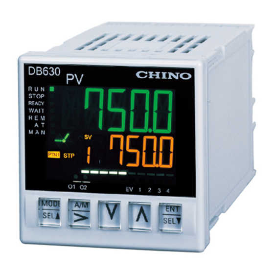
Page 39: Names Of Various Parts
[DB600] General Instruction Manual 3 Names of various parts 3-1 Entire overview Display Terminals Display Terminals Marking Marking 【DB630 【DB650】 】 Display Terminals Marking 【DB670】 - 37 -... -
Page 40: Name And Function Of Display
[DB600] General Instruction Manual 3-2 Name and function of display ① ③ Measured value (PV)/ Parameter setting title Cursor for setting parameter Displays measured value (PV) on Displays cursor by pressing [>] key when following operation screen Cursor the parameter is switchable digits during ・... - Page 41 [DB600] General Instruction Manual ⑦ ⑨ Operating condition display Pattern No. (program operation ON) *with program function Constant value operation (program operation OFF) specifications Lights while constant operation RUN. PTN1 Pattern No.1 Executing pattern No. lights while displaying operation screen/ MODE0 STOP (Unused) executing SV and displaying executing...
-
Page 42: Character Display
[DB600] General Instruction Manual 3-3 Character display 11-segment is used for display of this instrument. Display of alphabet, numbers and sign as follows. Alphabet A B C D E F G H J K L M N O P Q R S T U V W X Y Z ... -
Page 43: Operation
[DB600] General Instruction Manual 4 Operation 4-1 Cautions on power ON Understand the following contents before you start operation. Output on power ON Note that control may start form large output when the power is turned ON depending on the deviation (difference between PV and SV). -
Page 44: Constant Value Operation
[DB600] General Instruction Manual Operation screen (constant value operation) 4-2 Constant value operation 4-2-1 Setting overview Allows you to monitor/operate the constant value operation screen. 4-2-2 Setting screen and function Setting item Function PV/SV Displays the measured value (PV). □ □ "... - Page 45 [DB600] General Instruction Manual Operation screen (constant value operation) PV/OUT1 Displays the output 1 value. □ □ "□ □ " Output 1 value[%] □ □ □ * The setting range is limited by "Executing output limiter "□ " (MODE0)". ▲SEL↑ ↓▼SEL While the PV/OUT1 screen is displayed, [OUT] in the front lights.
- Page 46 [DB600] General Instruction Manual Operation screen (constant value operation) AUTO/ Switch the output between AUTO and MANUAL. MANUAL output switch "□ " AUTO output □ " " MANUAL output For the specification with 2 outputs, the output 1 and output 2 will switch ▲SEL↑...
- Page 47 [DB600] General Instruction Manual Operation screen (constant value operation) Timer 1 elapsed time Displays the elapsed time of timer 1. "□ □ □ □ " Timer 1 elapsed time [Second] □ □ □ □ " " ▲SEL↑ ↓▼SEL This display is available when "Timer 1" is assigned to "External input (MODEd)" for the specification with external signal input.
- Page 48 [DB600] General Instruction Manual Operation screen (constant value operation) CT measured value Displays the heater current value. □ □ □ "□ □ □ " Heater current value [A] □ "□ □ " "□ " Measured value not obtained Immediately after power start The pulse ON time is minimal (short cycle, etc.) after measured value is not obtained This display is available for the ON-OFF pulse/SSR drive pulse output type on the...
- Page 49 [DB600] General Instruction Manual Operation screen (constant value operation) PID auto tuning Starts/checks/forcibly terminates PID auto tuning. The result of PID auto tuning for the output 1 is stored in the following parameters □ □ □ automatically. □ □ • Executing PID (MODE0) •...
- Page 50 [DB600] General Instruction Manual Operation screen (constant value operation) FB tuning Starts/checks/forcibly terminates FB auto tuning. The result of FB tuning is stored in the following parameters automatically. □ □ □ • Feedback zero (MODE6) □ □ • Feedback span (MODE6) Auto tuning not executed ▲SEL↑...
-
Page 51: Run/Ready Status
[DB600] General Instruction Manual Operation screen (constant value operation) Constant value Sets the execution No. selection for constant value operation. operation "□ □ execution No. selection " Constant value operation execution No. 1 to 8 □ □ "□ □ " Set the execution No. -
Page 52: Program Operation
[DB600] General Instruction Manual Operation screen (program operation) 4-3 Program operation 4-3-1 Setting overview Allows you to monitor/operate the program operation screen. 4-3-2 Setting screen and function Setting item Function PV/SV Displays the measured value (PV). □ □ " " Measured value (PV) □... - Page 53 [DB600] General Instruction Manual Operation screen (program operation) PV/step time Displays the elapsed/remaining time of the step for program operation. □ □ "□ □ " Step elapsed/remaining time [Hour : Minute] or [Minute : □ □ Second] " " ▲SEL↑ ↓▼SEL The elapsed or remaining time is displayed according to the setting of "Operation screen time display (MODE2)".
- Page 54 [DB600] General Instruction Manual Operation screen (program operation) AUTO/ Switch the output between AUTO and MANUAL. MANUAL output switch "□ " AUTO output □ MANUAL output " " For the specification with 2 outputs, the output 1 and output 2 will be changed ▲SEL↑...
- Page 55 [DB600] General Instruction Manual Operation screen (program operation) Timer 1 elapsed time Displays the elapsed time of timer 1. "□ □ □ □ " Timer 1 elapsed time [sec] □ □ □ □ " " ▲SEL↑ ↓▼SEL This display is available when "Timer 1" is assigned to "External input (MODEd)" for the specification with external signal input.
- Page 56 [DB600] General Instruction Manual Operation screen (program operation) CT measured value Displays the heater current value. □ □ □ "□ □ □ " Heater current value [A] □ "□ □ " "□ " Measured value not obtained ▲SEL↑ ↓▼SEL Immediately after power-ON The pulse ON time is minimal (short cycle, etc.) after measured value is not obtained.
- Page 57 [DB600] General Instruction Manual Operation screen (program operation) PID auto tuning Starts/checks/forcibly terminates PID auto tuning. The result of PID auto tuning is stored in the following parameters automatically. □ □ □ Executing PID (MODE0) □ □ PID, 8 types (MODE3) * Of the 8 types, only the numbers for "Execution No.
- Page 58 [DB600] General Instruction Manual Operation screen (program operation) FB tuning Starts/checks/forcibly terminates FB auto tuning. The result of FB tuning is stored in the following parameters automatically. □ □ □ Feedback zero (MODE6) □ □ Feedback span (MODE6) Auto tuning not executed ▲SEL↑...
- Page 59 [DB600] General Instruction Manual Operation screen (program operation) Pattern No. selection Displays/sets the pattern No. for program operation start. "□ □ " Pattern No. 1 to 4 □ □ (Displays only the pattern No. with "Number of steps (MODE2)" "□ □ "...
-
Page 60: Program Operation Method
[DB600] General Instruction Manual Operation screen (program operation) 4-3-3 Program operation method The program operation can be executed using any of the following means. Parameters on the program operation screen External signal input Communication Operation Description RESET (cancelled) status of program operation. RESET ... -
Page 61: Auto/Manual Output Operation
[DB600] General Instruction Manual Operation screen (program operation) 4-4 AUTO/MANUAL output operation Switching between AUTO and MANUAL outputs can be done by any of the followings. Press and hold the key (with the operation screen displayed) Parameters on the operation screen ... -
Page 62: Cautions For Operation
[DB600] General Instruction Manual Operation screen (program operation) 4-5 Cautions for operation 4-5-1 Setting/changing a parameter during operation Setting/changing a parameter during operation is available except on some setting screens. Please pay attention to set/change a parameter during control operation since some parameters may negatively affect the control. -
Page 63: Setting Operations
[DB600] General Instruction Manual 5 Setting operations 5-1 Basics of setting 5-1-1 Setting screen display The setting screens are grouped by MODE. See "9-3 Parameter directory list" to find the location of desired setting screen. The following figure shows the screen transition of the operation screen, MODE screen and setting screen. -
Page 64: Basic Operations On The Setting Screen
[DB600] General Instruction Manual 5-1-2 Basic operations on the setting screen Power ON Refer to the parameter directory list See "9-3Parameter directory list Switch to the MODE screen from the operation screen Press and hold the key. Select the MODE screen Press the key. -
Page 65: How To Operate Parameter Setting
[DB600] General Instruction Manual Release key lock You cannot set/change a parameter when the key lock is enabled. At a registration of set contents, the PV display screen shows " " and a measured value (PV) alternately. See the section 5-14 to disable the key lock. ... - Page 66 [DB600] General Instruction Manual Press the key to display the group No. 1 (select the group No. using the key). Display the event 1 setting screen using the key. Pressing the key brings a cursor under the fifth digit of setting value. Set or change the event value using the keys (increase or decrease the value by the up/down key and move the digit by the right key).
-
Page 67: Precautions For Setting
[DB600] General Instruction Manual Cancelling a parameter setting To cancel a parameter setting/changing in the middle of the process (the dot at the first digit of setting value is blinking), press the key. After cancelling, the dot turns off and the previous setting value is displayed. -
Page 68: Mode0 [Executing Parameter]
[DB600] General Instruction Manual MODE 0 5-2 MODE0 [Executing parameter] 5-2-1 Setting overview MODE0 allows you to set/change parameters during operation. The set contents of MODE0 executing parameters are synchronized with MODE2 and MODE3 parameters of the same type. 5-2-2 Setting screen and function Setting item Function... - Page 69 [DB600] General Instruction Manual MODE 0 Executing event 2 Deviation alarm: SV decimal point Absolute value deviation alarm: SV decimal point Setting value alarm: SV decimal point Output value alarm: 1 digit Heater disconnection alarm: 1 digit Timer alarm: None ▲SEL↑...
- Page 70 [DB600] General Instruction Manual MODE 0 Executing output limiter Sets/changes the lower limit of executing output limiter. lower limit "□ □ " Lower limit of executing output limiter [%] □ □ □ "□ " Use the [ ], [ ] and [ENT] keys to set the lower limit of executing output limiter. ▲SEL↑...
-
Page 71: Changing An Executing Step
[DB600] General Instruction Manual MODE 0 5-2-3 Changing an executing step When an executing SV and step time are changed during program operation, the changes will be reflected in the executing step. Since it is synchronized with the set contents of MODE2 program pattern, the step settings will also be reflected in the next operation. -
Page 72: Mode1 [Constant Value Operation Parameter]
[DB600] General Instruction Manual MODE 1 5-3 MODE1 [Constant value operation parameter] 5-3-1 Setting overview MODE1 provides the constant value operation related settings. Constant value operation is performed using a constant setting value (SV). 5-3-2 Setting screen and function Setting item Function MODE1 initial screen MODE1 (constant value operation parameter) initial screen... -
Page 73: Rate Of Change
[DB600] General Instruction Manual MODE 1 5-3-3 SV rate of change This function is used to apply an SV change gradually, not immediately. Rise and fall settings are available for SV rate of change. Use the SV rate of change rise setting for upward operation, and the SV rate of change fall setting for downward operation. -
Page 74: Mode2 [Program Parameter]
[DB600] General Instruction Manual MODE 2 5-4 MODE2 [Program parameter] 5-4-1 Setting overview MODE2 provides the pattern related settings for program operation. The display is available only for the specification with program function. Program operation changes a target value with time according to the preset program pattern. A program pattern consists of multiple steps, and it can be created by setting a target value and time necessary for each step. - Page 75 [DB600] General Instruction Manual MODE 2 Program/ Switches the operation between program operation and constant value operation. constant value operation switch "□ □ " Operation screen switches to the constant value operation □ □ □ screen to perform constant value operation. "□...
- Page 76 [DB600] General Instruction Manual MODE 2 Pattern repeat Set this to operate a whole pattern (from the step No. 00 to the end step No.) repeatedly. (Example 1) Number of pattern execution = Pattern repeat count + 1 □ □ □ □ "□...
- Page 77 [DB600] General Instruction Manual MODE 2 Pattern No./ Displays or selects an arbitrary pattern No./step No. Start step No. "□ " Select a pattern No. and step No. of the parameter group □ displayed when the [SEL] key is pressed. "□...
- Page 78 [DB600] General Instruction Manual MODE 2 Step time Sets a step time necessary. □ "□ □ " Time necessary of step □ □ " " Use the [ ], [ ] and [ENT] keys to set the step time. ▲SEL↑...
- Page 79 [DB600] General Instruction Manual MODE 2 Output 2 at END Sets the output 2 in the program operation END status. "□ " Constant value control performed with the displayed SV □ "□ □ " Fixed value output [%] "□ " ▲SEL↑...
-
Page 80: Program Pattern Setting
[DB600] General Instruction Manual MODE 2 5-4-3 Program pattern setting Up to four patterns can be set, allowing you to select a desired pattern during operation. Example of program pattern setting Pattern Step No. 00 Number of steps PV start SV SV [°C] 100 100 150 150 200 200 250 250 300 300 200 200 Time [H:M]... - Page 81 [DB600] General Instruction Manual MODE 2 Step type and setting example Rise Keep Fall Measured Measured Measured Attainment target (SV) of value value value previous step Attainment target (SV) Attainment target (SV) Attainment target (SV) 1h 30min 1h 30min Time Time Time Target value: 500...
-
Page 82: Selecting The Start Method For Program
[DB600] General Instruction Manual MODE 2 5-4-4 Selecting the start method for program operation You can select either SV start or PV start for the start point of operation. SV setting is available with PV start selected. With SV start selected, operation starts with a start SV and heads toward a target value regardless of measured value (PV). -
Page 83: Mode3 [Group Parameter]
[DB600] General Instruction Manual MODE 3 5-5 MODE3 [Group parameter] 5-5-1 Setting overview MODE3 provides the settings for main control parameters. 8 parameters are grouped as one, and you can register an execution No. When constant value operation and each step of program pattern is performed, a group parameter can be used. - Page 84 [DB600] General Instruction Manual MODE 3 Event 4 (8 types) ▲SEL↑ ↓▼SEL P (8 types) Sets the P constant for 8 types. □ "□ □ □ " Two-position control □ □ □ "□ □ □ " P constant (PID control) 0.1 to 999.9 [%] "□...
-
Page 85: Setting 8 Parameters For Each Group
[DB600] General Instruction Manual MODE 3 5-5-3 Setting 8 parameters for each group 8 sets of the control related main parameters including SV for constant value operation can be set on this instrument. They are registered as group No. 1 to 8. You can just select a group No. that contains desired parameters and start operation immediately. -
Page 86: Mode4 [Event Parameter]
[DB600] General Instruction Manual MODE 4 5-6 MODE4 [Event parameter] 5-6-1 Setting overview MODE4 provides the event related settings. Events operate regardless of the operation screen. Event No.1 to No.9 can be set with or without output terminal. 5-6-2 Setting screen and function Setting item Function MODE4 initial screen... -
Page 87: Event Mode
[DB600] General Instruction Manual MODE 4 Event extension Sets the event extension function. function The function becomes effective when the event mode is alarm event (excluding □ (Event No. 1 to No. 4) heater disconnection alarm/timer alarm/FAIL alarm). □ □ "□... -
Page 88: Event Deadband
[DB600] General Instruction Manual MODE 4 Example) Event output with event extension function "Event standby" set for absolute value lower limit alarm Event output range with "Event standby" set Reference Event dead-band (db Event value Normal event output range Event activation range Power ON Activated Cleared ... -
Page 89: Mode5 [Input Parameter]
[DB600] General Instruction Manual MODE 5 5-7 MODE5 [Input parameter] 5-7-1 Setting overview MODE5 provides the input (measurement) related settings. Configures the settings related to the input type, measuring range, condition, and scale. 5-7-2 Setting screen and function Setting item Function MODE5 initial screen MODE5 (input parameter) initial screen... - Page 90 [DB600] General Instruction Manual MODE 5 Unit Checks the unit. □ "□ □ □ " ºC □ □ □ "□ □ □ " "□ □ □ □ " ▲SEL↑ ↓▼SEL No parameter is set/changed by the [], [] and [ENT] keys. Measuring range lower Sets the lower limit of measuring range.
-
Page 91: Input Type, Measuring Range, And Linear
[DB600] General Instruction Manual MODE 5 SV limiter lower limit Sets the lower limit of SV limiter. □ " " -1999.9 to 3000.0 The unit can be °C, V or mV. " " ▲SEL↑ ↓▼SEL Use the [], [] and [ENT] keys to set the lower limit of SV limiter. Use the [>] key to move the cursor to the right digit. -
Page 92: Input Correction
[DB600] General Instruction Manual MODE 5 5-7-4 Input correction Sets the sensor correction and digital filter. Sensor correction Adds a correction value to measured value (PV) and uses the result for the instrument display or control. This function provides a fine adjustment for the case a variation of measured value is observed between the instrument and other instruments. -
Page 93: Mode6 [Control Parameter]
[DB600] General Instruction Manual MODE 6 5-8 MODE6 [Control parameter] 5-8-1 Setting overview MODE6 is provided the output related settings. A condition or limit can be added to the output. 5-8-2 Setting screen and function Setting item Function MODE6 initial screen MODE6 (control parameter) initial screen Pressing the [ ... - Page 94 [DB600] General Instruction Manual MODE 6 PID dead band / Sets the PID dead band [PID control]/output dead band [two-position control]. output dead band □ □ □ "□ □ □ " Function OFF [PID control] □ □ □ * For the case of two-position control (P = 0.0%), operation is performed with the output dead band 0.1% even if 0.0% is set.
- Page 95 [DB600] General Instruction Manual MODE 6 Output variation limiter Sets the output variation limiter for fall. for fall □ " " Function OFF(-100.0%) □ " " -99.9 to -0.1 [%] □ □ " " ▲SEL↑ ↓▼SEL Use the [ ], [ ] and [ENT] keys to set the output variation limiter for fall. Use the [>] key to move the cursor to the right digit.
-
Page 96: Pulse Cycle
[DB600] General Instruction Manual MODE 6 Preset manual Sets the preset manual. "□ □ " -5.0 to 105.0 [%] □ □ □ "□ " Use the [ ], [ ] and [ENT] keys to set the preset manual. ▲SEL↑... -
Page 97: Pid Dead Band/Output Dead Band
[DB600] General Instruction Manual MODE 6 5-8-5 PID dead band/output dead band For the case of PID control, disturbance of control by steady noise is reduced when the deviation (difference between PV and SV) is small. If a set dead band is too large, a residual deviation (offset) may occur more frequently. For the case of two-position control, there are only two status outputs available: ON and OFF. -
Page 98: Fixed Output Setting
[DB600] General Instruction Manual MODE 6 5-8-8 Fixed output setting The output range is limited by the setting of "Output limiter (MODE0 and MODE3)". Output preset In P control operation, the control calculation output will be 50% when the deviation is zero (PV = SV). This output value can be set arbitrarily. -
Page 99: Mode7 [Output 2 Parameter]
[DB600] General Instruction Manual MODE 7 5-9 MODE7 [Output 2 parameter] 5-9-1 Setting overview MODE7 provides the output 2 related settings. The display is available only for the specification with 2 output. Two different outputs are made from individual terminals for one SV. The PID constant, output limiter, control action, etc. - Page 100 [DB600] General Instruction Manual MODE 7 Output 2 gap Sets the gap for the output 2. (PID control calculation) □ " " -100.0 to 100.0 [%] □ □ □ "□ " ▲SEL↑ ↓▼SEL The display appears only when "Output 2 control system (MODE7)" is set to "...
-
Page 101: Output 2 Control System
[DB600] General Instruction Manual MODE 7 Output 2 Sets the pulse cycle for the output 2. pulse cycle "□ □ □ □ " 1 to 180 [sec] □ □ □ "□ □ " ▲SEL↑ ↓▼SEL The display appears when the output 2 uses ON-OFF pulse/SSR drive pulse output type. -
Page 102: Modea [Communication Parameter]
[DB600] General Instruction Manual MODE a 5-10 MODEa [Communication parameter] 5-10-1 Setting overview MODEa provides the communication related settings. The display is available only for the specification with communication interface. This section describes the settings only. Read the separate instruction manual "Communication Interface" for general instructions for handling. - Page 103 [DB600] General Instruction Manual MODE a Communication Sets the communication character. character □ "□ □ " 7-bit/even parity/stop bit 1 □ □ "□ □ " 7-bit/even parity/stop bit 2 "□ □ " 7-bit/odd parity/stop bit 1 "□ □ " 7-bit/odd parity/stop bit 2 ▲SEL↑...
-
Page 104: Modeb [Transmission Output Parameter]
[DB600] General Instruction Manual MODE b 5-11 MODEb [Transmission output parameter] 5-11-1 Setting overview MODEb provides the settings related to the transmission signal output. The display is available only for the specification with transmission signal output. The measured value, setting value, output value, output 2 value (only for the specification with 2 outputs), and FB measured value are converted into 4 to 20mA, 0 to 1V, or 0 to 10V signal to output. -
Page 105: Transmission Scale
[DB600] General Instruction Manual MODE b 5-11-3 Transmission scale This function is used to set the scale for transmission signal output (analog signal). Set the transmission signal output range so that the transmission output ranges from 0% (transmission scale zero) to 100% (transmission scale span). Measuring (Lower limit) (Upper limit) -
Page 106: Modec [Remote Input Parameter]
[DB600] General Instruction Manual MODE c 5-12 MODEc [Remote input parameter] 5-12-1 Setting overview MODEc provides the remote input related settings. The display is available only for the specification with communication interface or remote signal input. The external signal input enables switching between remote and local, and SV setting in the remote operation. -
Page 107: Remote/Local Switch
[DB600] General Instruction Manual MODE c Remote scale zero Sets the remote scale zero. " " -1999.9 to 3000.0 " " The display appears for the specification with remote signal input. ▲SEL↑ ↓▼SEL Use the [ ], [ ] and [ENT] keys to set the remote scale zero. Use the [>] key to move the cursor to the right digit. -
Page 108: Correcting Remote Sv Input
[DB600] General Instruction Manual MODE c 5-12-4 Correcting remote SV input Set the remote SV shift and remote filter. Remote SV shift This function is used to correct the SV of remote signal input. The SV is shifted by the setting value according to the remote signal input (parallel shift). -
Page 109: Moded [External Input Parameter]
[DB600] General Instruction Manual MODE d 5-13 MODEd [External input parameter] 5-13-1 Setting overview MODEd provides the settings related to the external signal input. The display is available only for the specification with external signal input. External input is enabled by setting a function available for assignment to the external no voltage contact input number. - Page 110 [DB600] General Instruction Manual MODE d External input 5 Sets the external input 5. □ □ □ □ Use the [ ], [ ] and [ENT] keys to set the external input 5. ▲SEL↑ ↓▼SEL External input 6 Sets the external input 6.
-
Page 111: Modet [System Parameter]
[DB600] General Instruction Manual MODE d 5-14 MODEt [System parameter] 5-14-1 Setting overview MODEt provides the system related settings. 5-14-2 Setting screen and function Setting item Function MODEt initial screen MODEt (system parameter) initial screen Pressing the [ ] key makes a switch to the MODEd, MODEc, MODEb, MODE7 or (System parameter) MODE6 screen. - Page 112 [DB600] General Instruction Manual MODE d Operation initial screen Sets the operation initial screen. □ " " PV/SV display screen □ □ □ "□ " PV/step time display screen * This display is available for the specification with program function. ▲SEL↑...
-
Page 113: Detailed Description For Main Function
[DB600] General instruction manual 6 Detailed description for main function 6-1 Measuring range The instrument adopts universal input to allow settings of various input types. Set the input type most appropriate for the sensor and scale range to be used in actual operation. For thermocouple and resistance thermometer, check the applicable standard before setting the input type. -
Page 114: Linear Scale
[DB600] General instruction manual 6-2 Linear scale The default values of measuring range and linear scale are set as follows for the linear input (mV, V, mA). Input type Scale range Measuring range (default) Linear scale range (default) 20mV -20.00 to 20.00mV 0.00 to 20.00mV 0.0 to 2000.0 100mV... -
Page 115: Alarm Event Type
[DB600] General instruction manual 6-3 Alarm event type The alarm event comes in a variety of types as shown below. Event output range with "Event standby" set SV: Setting value MV: Output value Normal event output range AL: Event value db: Event dead-band Event activation range Absolute value upper limit alarm... - Page 116 [DB600] General instruction manual Event output range with "Event standby" set SV: Setting value MV: Output value Normal event output range AL: Event value db: Event dead-band Event activation range Absolute value deviation upper limit alarm Event output when the difference between a setting value (SV) and measured value (PV) exceeds a certain value.
- Page 117 [DB600] General instruction manual Event output range with "Event standby" set SV: Setting value MV: Output value Normal event output range AL: Event value db: Event dead-band Event activation range Setting value upper limit alarm Upper limit alarm against a setting value (SV). ...
- Page 118 [DB600] General instruction manual Even output range AL: Event value db: Event dead-band Event activation range Heater upper limit alarm (heater overcurrent alarm) Event output when heater overcurrent occurs. A current transformer (CT) is used to detect heater overcurrent. Activation condition AL <...
-
Page 119: Status Event
[DB600] General instruction manual 6-4 Status event The status event comes in a variety of types as shown below. For the event output specification, various status event types can be outputted. "0" Function Name Description Status event at constant value operation RUN. "□... -
Page 120: Auto Tuning
[DB600] General instruction manual 6-5 Auto tuning The auto tuning (AT) function is used to calculate PID constant automatically. It is available for the output 1 and output 2. The tuning is performed on the executing SV and executable in the constant value operation RUN status or program operation RUN status (except program end status). -
Page 121: Pid Control
[DB600] General instruction manual 6-6 PID control This is the most common control algorithm which are combined from three controls: P (proportional), I (integral) and D (derivative) controls. PID constant is used to associate the deviation (difference between PV and SV) with the output level. A good control result can be obtained by optimizing P, I and D values. -
Page 122: D Control
[DB600] General instruction manual 6-6-3 D control D control is used to make output at a level proportional to the variation of deviation. It determines the response performance to disturbance. Dead time or phase lag caused by lag element is compensated. The output level is limited, however, because the gain increases in the high frequency area. -
Page 123: Actuator Adjustment For On-Off Servo
[DB600] General instruction manual 6-7 Actuator adjustment for ON-OFF servo output type When the ON-OFF servo output type is used, the instrument and the actuator (motor, etc.) need to be adjusted. Generally the adjustment is performed automatically. Fine adjustment can be done manually; however, if you are using the instrument for the first time, make sure to perform auto adjustment first and then perform fine adjustment manually. -
Page 124: Manual Adjustment
[DB600] General instruction manual 6-7-2 Manual adjustment (1) Initialization of setting value Before starting the adjustment, change the settings of "Feedback zero/span (MODE6)" and "Feedback dead band (MODE6)" to defaults (feedback zero: 0.0%, feedback span: 100.0%, feedback dead band: 4.0%). ... -
Page 125: Outputs
[DB600] General instruction manual 6-8 2 Outputs Set the control calculation method in MODE7 for the specification with 2 outputs. 6-8-1 PID control calculation PID calculation is performed at the heating control and cooling control output sides individually. Normally, the output 1 is used for heating operation (set "Control action (MODE6)" to "Heating control") and the output 2 is used for cooling operation (set "Control action (MODE7)"... -
Page 126: Split Control Calculation
[DB600] General instruction manual 6-8-2 Split control calculation This is a matching box calculation method performed based on the PID calculation result of output 1. Sprit Direct is used for the cooling control output. Set the output level for the PID calculation result within the range of 0 to 60%. -
Page 127: Transmission
[DB600] General instruction manual 6-9-2 Transmission scale setting (PV /SV transmission) For temperature input, set a value within the measuring range. Input type ··················· K1(-200 to 1370°C) Transmission signal ··· 4 to 20mA Transmission scale ···· Zero: 400°C, span: 1000°C Measuring range... -
Page 128: Remote Signal Input
[DB600] General instruction manual 6-10 Remote signal input This function allows you to set SV using external analog signal. For example, you can use the instrument as a simple program controller by setting "Transmission type (MODEb)" of the instrument (specification with program function) to "SV transmission signal output" and connecting it to another controller (specification with remote signal input). -
Page 129: Cascade Control
[DB600] General instruction manual 6-10-2 Cascade control The instrument (specification with remote signal input) can be used as the secondary controller in a cascade control loop. See the following calculation block diagram of cascade control. Measurement Sensor input Output PID calculation Primary Remote signal Cascade... -
Page 130: External Signal Input
[DB600] General instruction manual 6-11 External signal input For the specification with external signal input a specific function can be assigned using the conduction signal (ON/OFF) of the external no voltage contact signal (relay, switch, open collector signal, etc.). Assign an external signal input function and terminal number with "External input 1 to 7 (MODEd)". - Page 131 [DB600] General instruction manual Function Description Resets (clears) the event output. " " Controls the specified external signal input with instantaneous signal. Resets the event Event reset output after approx. 0.5 seconds or more from entering the conduction (ON) state. The non-conduction (OFF) state is entered immediately after a reset to restore the normal condition.
- Page 132 [DB600] General instruction manual Function Description Resets (cancels) the program operation. " " Controls the specified external signal input with instantaneous signal. Switches to the Program operation RESET RESET status after approx. 1.0 second or more from entering the conduction (ON) state. The non-conduction (OFF) state is entered immediately after a reset to restore the normal condition.
-
Page 133: Communication Interface
DB650/670. Insert the dedicated USB engineering cable "RZ-EC3" (sold separately) to establish communication with a PC. CHINO prepares the software for parameter setting. It will help you set various parameters easily using the USB engineering cable and PC. The communication specification of the engineering port is shown below. -
Page 134: Specification With Communication Interface
[DB600] General instruction manual Make sure to connect/disconnect the USB engineering cable to/from Caution ! the engineering port of the instrument while the instrument is energized. Note that the engineering port is designed for temporary connection for communication, not for constant connection. To enable the always-connected situation, specify the specification with communication interface at the time of purchase, and use the terminal at the back of the instrument for permanent connection. -
Page 135: Options
[DB600] General instruction manual 7 Options 7-1 Moisture prevention Moisture-proof coating is processed on the printed board inside the instrument. 7-2 Square roots A square roots is performed on the linear input (mV, V) to display the measured value (PV) and perform control calculation. -
Page 136: Accessories
[DB600] General instruction manual 7-4 Accessories 7-4-1 Terminal cover A terminal cover is available to prevent electric shock and protect the terminals. [DB630] [DB650] [DB670] 7-4-2 Contact protection terminal Connect a contact protection element to the relay output terminal of the instrument for noise removal. Make sure to connect to the load via a buffer relay or contact protection element for relay outputs such as ON-OFF pulse, ON-OFF servo and event outputs. -
Page 137: Maintenance And Inspection
8 Maintenance and inspection 8-1 Error display When an error occurs in the system, the error No. shown below will be displayed for approx. two seconds. Check the error contents and contact the dealer or your nearest CHINO office. Error No. Error contents... -
Page 138: Troubleshooting
If the above troubleshooting does not improve the situation, contact the dealer (who does instrumentation or installation work, or sells the product) or your nearest CHINO office. Contact the dealer or your nearest CHINO office when repair or Warning !... -
Page 139: Inspection
Periodical accuracy check for measured value (PV), transmission signal output, etc. should be performed if necessary. The accuracy of those items may be slightly reduced over time from the point of purchase. We perform accuracy check for you. If you need it, contact the dealer or your nearest CHINO office. 8-4-3 Overhaul To maintain reliable operation for a long time, we recommend an overhaul after two or three years. -
Page 140: Appendix
[DB600] General instruction manual 9 Appendix 9-1 Specifications Input specifications Control specifications Input signal: Control interval Approx. 0.1 seconds Thermocouple B, R, S, N, K, E, J, T, U, L, WRe5-WRe26, Output type ON-OFF pulse output, ON-OFF servo W-WRe26, Platinel II, PtRh40-PtRh20, output (DB650 and DB670 only), current Au-Pt... - Page 141 [DB600] General instruction manual General specifications Weight DB630 (Without option) Approx. 120g Rated power voltage 100-240V AC(±10%) (With option) Approx. 135g 24V AC/DC(±10%) DB650 (Without option) Approx. 150g Rated power supply frequency 50/60Hz(±2%) (With option) Approx. 230g Maximum power consumption: DB670 (Without option) Approx.
- Page 142 [DB600] General instruction manual Storage condition Transmission signal output (option) Ambient temperature -20 to 60°C Output point 1 point * 10 to 30°C for long-term storage Output signal 4 to 20mA DC (load resistance 400Ohm Ambient humidity 5 to 95% RH (no condensation) or less) Vibration 0 m/s...
- Page 143 [DB600] General instruction manual Input type, measuring range and accuracy rating Input type Measuring range Measured accuracy Below 400°C :Out of specification 0.0 to 1820.0 400 to 800°C :±0.2%FS ±1digit Below 400°C :±0.2%FS ±1digit 0.0 to 1760.0 0.0 to 1760.0 0.0 to 1300.0 -200.0 to 1370.0 ±0.1% of FS±1digit...
-
Page 144: Parameter List
[DB600] General instruction manual 9-2 Parameter list Screen Item Setting range Default Screen Item Setting range Default □: No pattern copy □□ Operation PV (measured value) [°C] Pattern copy : Over-range : Copy pattern No. 1 to No. 2 □□to : Under-range : Copy pattern No. - Page 145 [DB600] General instruction manual Screen Item Setting range Default Screen Item Setting range Default □□□ □: Thermocouple B □□□ □□:MODBUS RTU MODE 5 Input type MODE a Communication □□ (0.0 to 1820.0°C) □□□ □: Thermocouple R protocol :MODBUS ASCII (0.0 to 1760.0°C) □□□...
-
Page 146: Parameter Directory List
[DB600] General instruction manual 9-3 Parameter directory list Constant Program value MODE 0 MODE 1 MODE 2 MODE 3 operation operation PV/SV PV/SV Constant Group Measured value / Measured value / Execution Program operation operation set value set value parameter parameter parameter parameter... - Page 147 [DB600] General instruction manual MODE 4 MODE 5 MODE 6 MODE 7 MODE a MODE b MODE c MODE d MODE t Event Input Control Output 2 Communication Remote SV input External input System Transmission output parameter parameter parameter parameter parameter parameter parameter...
-
Page 148: Index
[DB600] General instruction manual 9-4 Index Local ..............104 Auto tuning ............47 Alarm event type ..........113 Measuring range ........... 88 Alarm event reset ..........44 Measuring range ..........111 A to Z PID ............... 119 Number of steps ............ 75 Cascade input ............. - Page 150 CHINO CORPORATION 32-8, KUMANO-CHO, ITABASHI-KU, TOKYO 173-8632 Telephone : 81-3-3956-2171 Facsimile : 81-3-3956-0915 Printed in Japan...
Need help?
Do you have a question about the DB600 Series and is the answer not in the manual?
Questions and answers