mru VARIOluxx User Manual
Hide thumbs
Also See for VARIOluxx:
- User manual (8 pages) ,
- User manual (80 pages) ,
- User manual (116 pages)
Table of Contents
Advertisement
Quick Links
Advertisement
Table of Contents

Related Manuals for mru VARIOluxx


Summary of Contents for mru VARIOluxx
- Page 1 VARIOluxx USER MANUAL 9442EN...
- Page 2 User Manual VARIOluxx Manufacturer: Legal notices / Intellectual property rights comments Original user manual © 2022 by MRU No part of this manual my be published in any form (print, photocopy, electronic media or any other publication form) without a written approval by the publisher.
- Page 3 Electrochemical sensors are by their operating principle not only sensitive to the gas they are intended for, but for other gases as well. This cross sensitivity is compensated by MRU for the typical application of flue gas analysis. However, unusual high concentration levels of single gas components might lead to •...
-
Page 4: Table Of Contents
User Manual VARIOluxx Table of content Information for product and safety ..........8 1.1. Safety manual ....................8 1.2. Safety precautions ..................8 Introduction ..................9 2.1. Intended use ....................9 2.2. About us ......................10 Description ..................12 3.1. Task ........................12 3.2. - Page 5 User Manual VARIOluxx 5.10. Analog input setup (4-20mA) ..............42 5.11. Connecting analyser with WIFI (WLAN) ..........43 5.12. Getting information about the network ..........45 5.13. Assigning a static IP address ..............46 5.14. Serial connectivity (RS485/USB) ............. 47 5.15.
- Page 6 User Manual VARIOluxx Deleting sites ......................71 Recalling stored measurements ............... 71 Delete stored measurements ................72 7.3. Data transfer via USB (CSV export) ............74 Extras ....................77 8.1. Open menu Extras ..................77 8.2. History ......................77 8.3.
- Page 7 User Manual VARIOluxx 13.5. Gas cooler strategy .................. 106 13.6. Calculated values and accessories ............. 107 13.7. Analysis and calculations ............... 107 13.8. Data communication ................108 13.9. Fuel type list ....................108 Options ..................109 14.1. Gas flow measurement ................109 Connect analyser to Pitot tube ..............
-
Page 8: Information For Product And Safety
User Manual VARIOluxx Information for product and safety 1.1. Safety manual All general information and safety precautions of MRU products are listed in the supplied separate safety manual. Therefore, this manual must be read and observed before the first use of the instrument . -
Page 9: Introduction
User Manual VARIOluxx Introduction • This manual enables you to understand and safely operate this MRU Analyser VARIOluxx. • Please read this manual with great vigilant and get familiar with the product before using it. • This analyser may only be operated by competent personnel and for its intended use. -
Page 10: About Us
(NO2), while the instrument itself and its screen shots display the gases in upper case letter only, i.e. (NO2). 2.2. About us The analyser is produced by the MRU GmbH in Neckarsulm, Germany (Founded in 1984), a medium sized company that is specialised in developing, producing and marketing high quality emission monitoring analysers. - Page 11 User Manual VARIOluxx MRU GmbH Fuchshalde 8 + 12 74172 Neckarsulm - Obereisesheim GERMANY Tel +49 71 32 99 62 0 (Front office) Tel +49 71 32 99 62 61 (Service) Fax +49 71 32 99 62 20 Email: info@mru.de Site: www.mru.eu...
-
Page 12: Description
User Manual VARIOluxx Description 3.1. Task The main task of the analyser is to analyse flue gases, as they are emitting from incinerators or engines. • The analyser is optimized for this purpose and includes all compo- nents from the gas sampling probe to data processing. -
Page 13: The Analyser
User Manual VARIOluxx Fresh air inlet Sample gas inlet Condensate outlet Diff. Pressure connector Vent collection box Vent outlet Sample gas filter (PTFE) Dust filter Humidity sensor Auto-zero solenoid valve CO purging pump Sample gas pump CO purge solenoid valve... -
Page 14: Connectors
User Manual VARIOluxx 3.4. Connectors Front side right Loudspeaker Ethernet (LAN) USB socket Second USB socket (option) RS485 (Option) Analog outputs 4 ... 20 mA Analog-inputs 4 … 20 mA Mains power supply Front side left Sample gas filter Condensate outlet port... -
Page 15: Probes
• Probe adapter set HPI for existing probe tubes (see chapter 14.5) for connecting ON-SITE existing 6- or 8-mm tubes to the probe han- dle INSTEAD of the enclosed MRU probe tube. But then no measurement of the flue gas temperature is possible... -
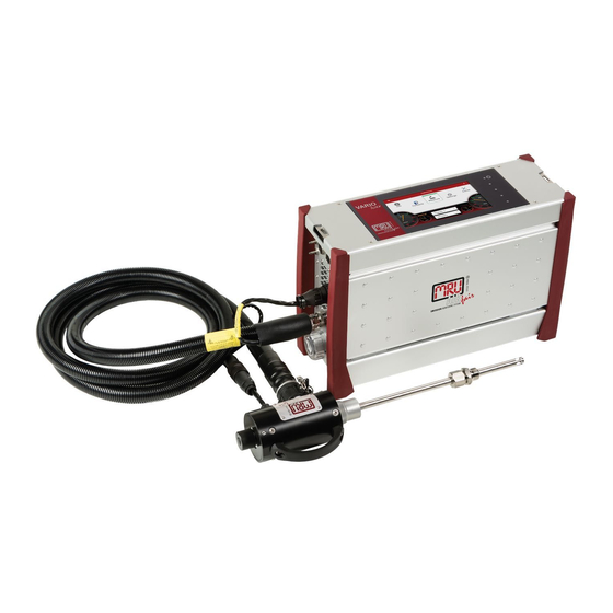
Page 16: Heated Gas Sampling Probe
User Manual VARIOluxx 3.6. Heated Gas sampling probe For interchangeable probe tube with flue gas temperature measurement using type K-thermoelement. Probe handle Probe tube Fast locking coupling Probe cone Cable plug (14-pin) Heated hose line Cable coupler (5-pin) Fast locking coupling Filter lock ►... - Page 17 User Manual VARIOluxx ATTENTION When measuring with coiled heated hose line, the hose line is destroyed due to strong heat development. ► Roll out the heated hose line completely for each measurement. NOTE Please note that heating hoses with 110V and 230V are offered.
-
Page 18: Unheated Gas Sampling Probe
User Manual VARIOluxx 3.7. Unheated Gas sampling probe Filter lock Fast locking coupling Cable coupler (5-pin) Cable plug (14-pin) Fast locking coupling Unheated hose line Probe cone Probe tube Probe handle ► Check the probe filter before and after every measurement. -
Page 19: Gas Conditioning
User Manual VARIOluxx 3.8. Gas conditioning The sucked sample gas is dried and filtered before it is fed to the sensors. A sample gas cooler with Peltier element is used for drying. The condensate liquid appearing in the gas cooler is pumped to the con- densate outlet by means of a peristaltic pump. -
Page 20: Operation
User Manual VARIOluxx 4 Operation 4.1. Commissioning The analyser leaves the factory assembled and ready for use. ► Check the analyser regarding completeness and integrity. ► Connect the analyser to the mains. The analyser switches on. The operating system boots. -
Page 21: Charging The Battery
User Manual VARIOluxx Power-on and reset Reserve Reserve LED display mains operation/battery charging mode Reserve Current flow rate Current temperatures heated hose Selected measuring program, e.g., Test or measurement program Current temperatures of NDIR bench Current temperatures of gas cooler Access to detailed information on the instrument components. -
Page 22: Switching On The Analyser
User Manual VARIOluxx 4.4. Switching on the analyser ► Touch the ⏻ button (1) for 3 sec. minimum LED lights blue ► Release the ⏻ button (1). Analyser runs up. 4.5. Switching off the analyser There are two possibilities to switch off the analyser. -
Page 23: Set The Analyser To Standby Mode
User Manual VARIOluxx 4.7. Set the analyser to standby mode The analyser is protected in standby mode. You cannot take measurements in standby mode. The actuators, for example pumps and gas coolers, are switched off as far as possible. Note that NDIR is not switched off. After you have left the standby mode, the analyser will start up again. -
Page 24: Back To Homescreen / Back To Measure
User Manual VARIOluxx 4.8. Back to homescreen / Back to measure As soon as the back button is displayed, you have the option to go back to the homescreen or go back to the measurement, from any window. ► Press for one second ... -
Page 25: Settings
User Manual VARIOluxx Settings After the analyser has been inspected and is ready for start-up it can be switched on and personalized settings can be entered. These settings can be changed at any time. 5.1. Open menu Settings ► Press Settings ... -
Page 26: Setting Date And Time
User Manual VARIOluxx Setting Range Description Language Select analyser language Country (fuel type) By changing the country, the O ref- erence values settings are lost. The fuel list is reset. Similarly, country- specific defaults and methods of measurement are selected as a re- sult. -
Page 27: Device Settings
User Manual VARIOluxx ► Set the desired time and date. ► Press ACCEPT. The set time and date are shown in the display. NOTE Note that the time setting is limited to +- 14 hours. The analyser displays a corresponding message. - Page 28 User Manual VARIOluxx Setting Range Description Combustion analysis ON/OFF Setting combustion analysis to ON allows for several calculation per- formed by the instrument, which are fuel type Negative gas readings ON/OFF Negative gas readings caused by temperature drift of a sensor are...
-
Page 29: Water Monitoring
User Manual VARIOluxx Modus Slave ID Modbus address of the instrument for the remote control via Modbus Hold delay after purge Time in which Analog outputs main- tain their value after zero-point measurement Aux connector Analogue input for TC, 0-10 V, 4...20mA, RS485... - Page 30 User Manual VARIOluxx A window appears. ► Set the permitted H20 deviation [ppm]. ► Confirm the value with ► Set the allowed duration of deviation [min]. ► Confirm the value with ► Set the time after the zero point has been taken, when water monitoring is to be started.
- Page 31 User Manual VARIOluxx The analyser continuously displays the newest H 0 value [ppm]. As soon as the permitted H 0 deviation [ppm] is exceeded, the sta- tus changes to: Overrun was detected. If the allowed duration of deviation [min] is exceeded, the status changes to: A second overrun during the allowed duration of deviation was detected.
-
Page 32: Averaging
User Manual VARIOluxx You can also set, that a zero point is taken automatically ► Activate take auto zero point. After a second overrun was detected, zeroing starts automatically. 5.6. Averaging You can set that a permanent averaging is performed. - Page 33 User Manual VARIOluxx You can set that at the start of an Auto-measurement (logging) the average values are reset. ► Activate Reset average when start logging. NOTE Note that average values are only exported for single measurements (from a certain point in time) in a CSV export.
-
Page 34: Interval Measurement
User Manual VARIOluxx 5.7. Interval measurement You have the possibility to perform an Interval measurement. You can set the duration of the Measurement time, the duration of the Standby time and the amount of the Measurement cycles. The analyser will go into standby mode between intervals. - Page 35 User Manual VARIOluxx ► Activate / deactivate whether the heated hose temperature should be monitored during heating. ► Activate / deactivate whether the probe temperature should be moni- tored during heating. ► Go to the menu Measure. ► Press the Context menu ...
- Page 36 User Manual VARIOluxx ► Select the desired site. The measuring window appears. ► Press A window appears. NOTE To stop displaying the window, press the button again. Information on the remaining time of the measurement and the re- maining measurement cycles is displayed.
- Page 37 User Manual VARIOluxx After the set standby time has elapsed, a warm-up phase is initi- ated. After the warm-up phase has elapsed, a zeroing is initiated. After taking the zero point, another measurement is started The process repeats itself according to the set amount of measure- ment cycles.
-
Page 38: Programs
User Manual VARIOluxx 5.8. Programs You can change the Program names. ► Open the menu Settings. See also chapter 5.1 Open menu Settings, S. 25. ► Press Programs. A window appears. ► Select the program you want to change the name for. -
Page 39: Analog Output Setup (4-20Ma)
User Manual VARIOluxx 5.9. Analog output setup (4-20mA) There are 8 Analog outputs (4-20 mA) available. Each Analog output (channel) is assigned a measured variable and an output range. Setting channel ► Open the menu Settings. See also chapter 5.1 Open menu Settings, S. 25. -
Page 40: Setting Lower / Higher Limit
User Manual VARIOluxx Setting lower / higher limit NOTE Setting lower limit (4mA) This setting determines the lower end value, corre- sponding to 4 mA. If the measured value falls below the set value, the Analog output stops at 4 mA. -
Page 41: Setting Analog Outputs During Zeroing
User Manual VARIOluxx Setting Analog outputs during zeroing Zeroing starts automatically. The display shows „zero“. The remaining time until the Zero point measurement ends is displayed. The following settings are possible: •Hold - The outputs kept the last values from before zeroing •2 mA - The outputs change to 2 mA to indicate the zero point... -
Page 42: Pin Assignment Of The 4-20 Ma Interface (Analog In/Out)
User Manual VARIOluxx Pin assignment of the 4-20 mA interface (Analog IN/OUT) ► Open the menu Settings. See also chapter 5.1 Open menu Settings, S. 25. ► Press „Analog output setup (4-20mA)“. A window appears. ► Press„Analog output setup (4-20mA)“. -
Page 43: Connecting Analyser With Wifi (Wlan)
User Manual VARIOluxx ► Go back. The values appear in the selection list. The incoming measurand is displayed. 5.11. Connecting analyser with WIFI (WLAN) ► Insert a WLAN-Stick into the Analyser. ► Open the menu Settings. See also chapter 5.1 Open menu Settings, S. 25. - Page 44 User Manual VARIOluxx ► Select the desired WLAN-Connection. A window appears. Enter the WLAN password. ► Press „OK“. A connection to the WLAN network is established. A WLAN symbol appears in the display. ► Touch the WLAN icon to see the WLAN IP.
-
Page 45: Getting Information About The Network
User Manual VARIOluxx ► Use the displayed WLAN -IP for MRU4win (in this example 192.168.43.53). See also Chapter 15.4 Connecting analyser with MRU4win, Page 111. 5.12. Getting information about the network ► Open the menu Settings. See also chapter 5.1 Open menu Settings, S. 25. -
Page 46: Assigning A Static Ip Address
User Manual VARIOluxx 5.13. Assigning a static IP address You have the possibility to assign a static IP address via Ethernet and WLAN. ► Open the menu Settings. See also chapter 5.1 Open menu Settings, S. 25. ► Press Network ... -
Page 47: Serial Connectivity (Rs485/Usb)
User Manual VARIOluxx 5.14. Serial connectivity (RS485/USB) You have the option of transferring data wirelessly with MRU4Win to a PC/notebook. Use the USB Bluetooth converter set (# art. no. 12992). The USB-Bluetooth converter set consists of two pre-paired and config- ured converters. - Page 48 User Manual VARIOluxx NOTE Ensure that under "Settings/General" the setting "Acti- vate Modbus" is checked. ► Select Livemeasurements. The menu Livemeasurements appears. ► Click Create Modbus Device. The window Modbus Settings appears. ► Enter the following parameters: • Device = 1113 Device •...
-
Page 49: Default Settings
User Manual VARIOluxx ► Click OK The Modbus Device is created. ► Click The connection is established. 5.15. Default settings You can reset the analyser to factory default. NOTE Note that when the analyser is reset to factory default all individual settings are lost. -
Page 50: Configuration Of Measurement Program
User Manual VARIOluxx ► Press OK. The analyser is reset to factory default 5.16. Configuration of measurement program The Analyser provides in the Measure menu various measurement programs, which can be selected in the main window. Each measuring program defines the properties of the measuring window:... -
Page 51: Setting Zoom
User Manual VARIOluxx You can replace the selected value field with the selected measured value. You can insert the selected measured value in place of the selected value field. The previously selected value field moves accordingly. ► Touch „replace “or „insert “. -
Page 52: Measurement
User Manual VARIOluxx Measurement 6.1. Preparing measurement CAUTION Acid from the condensate Acid burns may result from weakly acidic liquids from the condensate. ► If you come into contact with acid, wash the area im- mediately using a lot of water. -
Page 53: Operating Temperature
User Manual VARIOluxx Operating temperature The internal gas cooler operates at 5°C, which is the dew point of the sample gas to the sensors. Components along the gas line may be dam- aged if they are colder than 5°C and condensation appears internally. -
Page 54: Plug In Temperature Sensor
User Manual VARIOluxx Plug in Temperature sensor ► Plug the temperature sensor into the T-AIR connector (17). See also chapter 3.4 Connectors, Page 14. ► Open the ventilation flap and position the temperature sensor as shown below: Temperature sensor... -
Page 55: Switch-On, Warm-Up Phase, Zero Point
User Manual VARIOluxx NOTE The temperature sensor can remain plugged in perma- nently – even when transporting the analyser. Switch-on, warm-up phase, zero point After switching on, the instrument can always be operated, even if no gas analysis can take place during the warm-up phase. The instrument inde- pendently performs the following actions during the warm-up phase: •... -
Page 56: Repeated Zero Point
User Manual VARIOluxx In this case, check the ambient air. If the Setting “Analyser start with – stored zero point “is activated the ambient air is not checked See also Chapter 5.4 Device settings, Page 27. Repeated Zero point It is possible to start a manual zero-point measurement. -
Page 57: Use Last Valid Zero Point
User Manual VARIOluxx NOTE Please note that a manually initiated zeroing sets a new time point grid. This depends on the set interval auto- zero [h] in the menu Settings. Example: You have set a zero-point interval [h] of 4 h. The last automatic zeroing took place at 2 pm. -
Page 58: Select Source Zero Point (Gas)
User Manual VARIOluxx NOTE Please note that for the O2 sensor, regardless of this setting, a zero-point measurement is performed after each switch-on. Select Source zero point (gas) You can select whether zero-point gas is always sucked in via the fresh air inlet. -
Page 59: Charging State Of The Battery
User Manual VARIOluxx ► Choose the desired option. The zero gas is sucked in either via the probe or the fresh air inlet. NOTE After switching on, the first zero point is always taken via the fresh air inlet. -
Page 60: Attach Clip-On Filter
User Manual VARIOluxx The pump capacity should be approx. 112,5 ln/h, and thus 25% above the typical sample gas flow rate of 90 ln/h. Connect a hose to the Sample gas outlet port (10), if no electrochemi- cal sensor is installed. -
Page 61: Controlling Filters
User Manual VARIOluxx Controlling Filters The filters (probe filter and round filter) must be checked before and after each measurement. 6.2. Take a measurement Setting O2 reference and Fuel type ► Touch the menu „Measure “. The measurement window appears. -
Page 62: Starting The Measurement
User Manual VARIOluxx A window appears ► Set the desired CO threshold value. ► Touch “OK”. The setting is saved. The stored ppm value determines the CO shutdown threshold. If the measured value reaches this threshold, the second fresh air purge pump starts and the CO sensor is separated from the gas path by a valve. -
Page 63: Select Channels For Graphic Display
User Manual VARIOluxx ► Choose the desired site. The measured values are stored. The measurement continues until you switch off the analyser. See also Chapter Recalling stored measurements, Page 71. Select channels for graphic display You can select a maximum of eight channels and have them displayed graphically. - Page 64 User Manual VARIOluxx ► Press a measurand that you want to replace. A window appears. ► Select the desired measurand. ► Press OK. The measurand is replaced. You have the possibility to display two measurands simultaneously as a curve.
- Page 65 User Manual VARIOluxx ► Press the graphic symbol. A diagram appears. ► If necessary, touch to stop the graphical display. The measurement will be continued in the background. ► If necessary, touch to continue the graphical display. 65 / 129...
-
Page 66: Starting Auto-Measurement
User Manual VARIOluxx Starting Auto-measurement You can record the measured values for a defined period and have them displayed graphically. ► Touch the menu Measure. The measurement window appears. ► Touch the “Context menu” (19). A selection list appears. - Page 67 User Manual VARIOluxx ► Press the graphic symbol. A diagram appears. ► If necessary, press the gear wheel symbol to display other measurands in graphical form. You can also export or print the data of the automatic measurement. ► Insert a USB-stick into the analyser.
-
Page 68: Stopping Auto-Measurement
User Manual VARIOluxx NOTE If a zero point was taken during a Auto-measurement (manually initiated or by a set time interval), the meas- ured values are kept constant in the display. Immedi- ately before the end of the zeroing, the real measured values are displayed again. -
Page 69: Data Memory
User Manual VARIOluxx Data memory 7.1. Organizing data memory Base of the data memory of the analyser is a set of sites stored in the instrument. Every site exists of a unique site number and 12 freely usable text lines which can have, e.g., the address, customer name etc. -
Page 70: Changing Site Data
User Manual VARIOluxx The site is saved. Changing site data ► Touch the menu Sites. A selection list appears. ► Select the desired site. A window appears. ► Change the desired data. ► Touch „STORE “. The changes are stored. -
Page 71: Deleting Sites
User Manual VARIOluxx Deleting sites ► Press the menu Sites. A selection list appears. ► Select the desired site. A window appears. ► Press Delete. The site is deleted. Recalling stored measurements Stored measurement can be displayed individually for each site. -
Page 72: Delete Stored Measurements
User Manual VARIOluxx ► Touch „MEASUREMENTS “. A selection list appears. ► Touch the desired measurement. The measurement window appears. Delete stored measurements There are two ways to delete measurements. • You can delete measurements individually. • You can select several measurements and delete them at the simul- taneously. - Page 73 User Manual VARIOluxx Press MEASUREMENTS. The stored measurements are displayed. Delete single measurement ► Press A message appears. ► Press YES The selected measurement is deleted. Delete several measurements ► Select the measurements you want to delete. The button DELETE CHECKED becomes active.
-
Page 74: Data Transfer Via Usb (Csv Export)
User Manual VARIOluxx ► Press the button DELETE CHECKED. A message appears. ► Press YES. The selected measurements are deleted. 7.3. Data transfer via USB (CSV export) The data exchange format is CSV. A character-separated values (CSV) file is a simple text format for a database table. - Page 75 User Manual VARIOluxx ► Select the desired site. A window appears. ► Press MEASUREMENTS The stored measurements are displayed. You have the option to export measurements as single files. You have the option of exporting several measurements in one file.
- Page 76 User Manual VARIOluxx ► Press EXPORT CHECKED AS CSV or EXPORT CHECKED IN ONE FILE. Depending on the selection, the measurements are exported indi- vidually or all selected measurements are exported in one file. A message appears ► Select, if you want to export with header in file.
-
Page 77: Extras
User Manual VARIOluxx 8 Extras 8.1. Open menu Extras ► Press Extras A list appears ► Select the desired menu item. 8.2. History ► Open the menu Extras. See also chapter 8.1 Open menu Extras, S. 77 A selection list appears. - Page 78 User Manual VARIOluxx ► Choose the desired period time. The chosen time period is displayed graphically. ► If necessary, press A window appears. You have the possibility to change the displayed channels and to have them displayed graphically.
-
Page 79: System Extensions
User Manual VARIOluxx ► If necessary, press A window appears ► You can set min. and max. and the division of the selected channels. ► Press Ok, to exit the window. 8.3. System extensions You have the possibility to expand the analyser with options. -
Page 80: Connections
User Manual VARIOluxx ► Press System extensions A window appears. The options stored on the USB stick are displayed. ► Press UPDATE LIST, if no options are displayed. ► Select the desired Options. ► Press LOAD CHECKED OPTIONS. -
Page 81: Automatic Device Start
User Manual VARIOluxx 8.5. Automatic device start You have the possibility that the analyser performs an automatic device start at a time determined by yourself. ► Open the menu Extras See also chapter 8.1 Open menu Extras, Page 77. -
Page 82: Instrument Leak Test
User Manual VARIOluxx The system will shut down. After the analyser has shut down, an LED lights up to in dicate that an au- tomatic device start has been set 8.6. Instrument leak test The analyser device has an integrated leak test to check the tightness of the gas paths. -
Page 83: Printing Measurement Results
User Manual VARIOluxx NOTE With dirt and soot particles on the probe tube the test cap will not seal properly. ► The probe tip must be cleaned before you start this test. ► Seal off the tip of the probe a leak proof test cap. -
Page 84: Printing Current Measurement Results
User Manual VARIOluxx Printing current measurement results ► Switch on the printer. ► Go to the menu Measurement. The measurement window appears. ► Press the “Context menu” (19). A selection list appears. ► Press Print. The measurement is printed out with a slight delay. - Page 85 User Manual VARIOluxx ► Press MEASUREMENTS. The stored measurements are displayed. ► Press the desired measurement. The measurement window appears. ► Press the context menu (19). A selection list appears. ► Press „Print“. The measurement is printed out with a slight delay...
-
Page 86: Service
User Manual VARIOluxx Service 9.1. Open menu Service ► Press Service. A list appears. ► Select the desired menu item. 9.2. Service values This screen displays a number of internal parameters and their values. In case of unexpected behaviour of the analyser it might be helpful to com- municate those values to our worldwide service staff: https://www.mru.eu... -
Page 87: Performing Device Selftest
User Manual VARIOluxx 9.3. Performing Device selftest With the Device selftest you can test certain parameters of the analyser. ► Open the menu Service. See also chapter 9.1 Open menu Service, Page 86. ► Press Selftest device. A window appears. -
Page 88: Internal Log Settings
If the Device selftest for a particular parameter was not successful shown in the display. In the case of an Error message, please contact our customer service or contact one of the worldwide MRU service partners via www.mru.eu 9.4. Internal log settings The analyser stores internal parameters at regular intervals to allow for an optimized support from experienced service staff. -
Page 89: Copying Single Log Data
User Manual VARIOluxx A Symbol appears in the Display ► Press OK. The directory [serial number] Logg was created on the USB-Stick. The log files are saved in the directory [serial number]. After copying, the display shows "File(s) successfully copied". - Page 90 User Manual VARIOluxx ► Press the desired log file. A window appears. The desired log file appears in the window. ► Press COPY TO EXTERN USB-STICK. A window appears. The copy process is started. The directory [serial number] Logg was created on the USB-Stick.
-
Page 91: Export Ndir - Factors
User Manual VARIOluxx Export NDIR – Factors If your analyser has an NDIR cuvette, you can export the NDIR factors to a USB stick. ► Insert a USB-stick into the analyser. ► Open the menu Service. See also chapter 9.1 Open menu Service, Page 86. -
Page 92: Info
User Manual VARIOluxx 10 Info 10.1. Open menu Info ► Press Info. A window appears. ► Select the desired menu item. 10.2. Calling up device info In the menu Device info, you can, for example, display the serial number, the firmware version and version information for installed mod- ules and installed options. - Page 93 User Manual VARIOluxx ► Exit the window. ► Press OPTIONS. A window appears. The installed options are displayed. 93 / 129 MRU GmbH, D-74172 Neckarsulm...
-
Page 94: Device Usage
User Manual VARIOluxx 10.3. Device usage You have the possibility of displaying the operating time of the analyser, the total usage of certain analyser components and the remaining usage time until the next maintenance. ► Open the menu Info. See also chapter 10.1 Open menu Info, S.92. -
Page 95: Maintenance And Cleaning
User Manual VARIOluxx 11 Maintenance and cleaning 11.1. Cleaning and maintenance The analyser needs only low maintenance effort for long value preservation: CAUTION Acid from the condensate Acid burns may result from weakly acidic liquids from the condensate. ► If you come into contact with acid, wash the area im- mediately using a lot of water. -
Page 96: Simple Service Work
User Manual VARIOluxx 12 Simple service work 12.1. Information of the analyser components Information about analyser components is helpful in case of service or in- quiries. ► Touch A selection list appears. ► Choose the desired component of the analyser. -
Page 97: Updating The Firmware
User Manual VARIOluxx 12.2. Updating the firmware If necessary, you will receive a new released data package from the man- ufacturer for updating the firmware and the individual modules. The data package consists of a ZIP data package. The data package has the ending .mru. - Page 98 If no data package is displayed, save the received data package again on a USB stick. If the data package is not displayed again, contact cus- tomer service or one of the MRU service partners worldwide. 98 / 129 MRU GmbH, D-74172 Neckarsulm...
- Page 99 User Manual VARIOluxx ► Select the desired data package. A window appears. ► Select parts of the data package that you want to update. ► Press LOAD CHECKED PARTS A message appears. To conclude the update process, the analyser must be restarted.
-
Page 100: Update Firmware Of Single Modules
User Manual VARIOluxx ► Press YES. The analyser performs a restart. You can now update the software of single modules. Update firmware of single modules NOTE Note that you must first update the main firmware. Af- ter restarting, you can update the firmware of single modules. - Page 101 User Manual VARIOluxx ► Press YES. The update is started. After the update has been performed successfully, a message ap- pears. ► Press OK. ► Please restart the system. 101 / 129 MRU GmbH, D-74172 Neckarsulm...
-
Page 102: Specifications
User Manual VARIOluxx 13 Specifications The technical data listed here may differ depending on the analyser con- figuration. • means: included in the standard scope of each analyser O means: optional possible, availability depends on device configuration 13.1. Technical data Operating temperature +5°C - +45 °C... -
Page 103: Specifications Of Ndir Technology
User Manual VARIOluxx 13.2. Specifications of NDIR technology ArtNr. Gas Measuring Range Resolution Accuracy 10561 CO 1000...30.000 ppm 1 ppm ±10 ppm / 2% 40 Vol.% 0,01 Vol.% ±0,1 Vol.% / 2% 1000 ... 10.000 ppm 1 ppm ±10 ppm / 2% 1000...30.000 ppm... - Page 104 User Manual VARIOluxx Resolution Accuracy abs./reading ± 5ppm 5 % (0 … 1000 ppm) 10 % (> 1000 ppm) Response Time T90 < 30 s Option NO low Measuring Range 300 ppm Resolution 0,1 ppm Accuracy abs. / reading 2,0 ppm Electrochemical Sensor Nom.
- Page 105 User Manual VARIOluxx Electrochemical Sensor Nom. Measuring Range 0 - 2000 ppm Overload Range < 10000 ppm Resolution 1 ppm Accuracy abs./reading ± 5 ppm 10 % (0 – 500 ppm) 15 % (> 500 ppm) Response Time T90 < 40 s...
-
Page 106: Gas Sampling And Conditioning
User Manual VARIOluxx 13.4. Gas sampling and conditioning Max suction range gas pump 350 hPa gas flow typ 90 l/h Single Stage Gas cooler • Temperature Peltier cooler (during 5° C grid and battery operation) Batt operating hours with gas cooler... -
Page 107: Calculated Values And Accessories
User Manual VARIOluxx 13.6. Calculated values and accessories Measuring range (fuel type de- 0 - CO2 max. pendant) Accuracy abs. ± 0,3 Vol.% Dew point °C Losses qA 0 - 99,9 % Efficiency 0 - 120 % Measurement values available as... -
Page 108: Data Communication
Ο Analog I/O: 4x input, 8x output, 4... 20 mA Ο 13.9. Fuel type list This list is for Germany only. Fuel types from other countries can be obtained from MRU GmbH: Web page: www.mru.eu Germany O2max 20,96 Fuel CO2max... -
Page 109: Options
User Manual VARIOluxx 14 Options 14.1. Gas flow measurement With the option Gas flow measurement further measured values are avail- able: • v-flow • Flow rate Connect analyser to Pitot tube The following sketch shows an example of the connection of the analyser to a Pitot tube with thermocouple. -
Page 110: Parameter For Gas Flow Measurement
User Manual VARIOluxx NOTE Note that you can use either the connection T-AIR or the connection AUX. Parameter for gas flow measurement ► Press the menu Measure. The measurement window appears. ► Press the “Context menu” (19). A selection list appears ►... -
Page 111: Operating The Analyser In The Extended Temperature Range
User Manual VARIOluxx ► Change the desired parameters. NOTE You have the following options for measuring the tem- perature: • Via the probe (T-gas) • Via the connection T-AIR (T-air) • Via the connection AUX (AUX-tc) See also chapter Connect analyser to Pitot tube, Page 109. -
Page 112: Precautions For Use In The Extended Temperature Range
User Manual VARIOluxx The heating box is supplied with an external power supply unit. Precautions for use in the extended temperature range ► Ensure to switch on the analyser at a temperature of +5° or higher, as the analyser cannot defrost itself. -
Page 113: Operating Analyser With Nickel-Metal-Hybrid (Nihm)-Battery113
User Manual VARIOluxx Screws / Heating box spacer bolt Connection for external Condensate output on power supply Heating box 14.3. Operating analyser with Nickel-Metal-Hybrid (NiHM)-Battery ► Please note that the following information is only relevant for you if an optional NiHM-Battery is installed in your analyser. -
Page 114: Rs485 Extern (Option)
User Manual VARIOluxx The message appears 45 seconds after switching on. The message appears after 90 seconds if the power supply unit is removed during operation. 14.4. RS485 Extern (Option) RS485 interface with modbus RTU protocol for far distance data transfer over cable. -
Page 115: Screw Adapter Onto Hpi-Probe (Option)
User Manual VARIOluxx 14.5. Screw adapter onto HPI-Probe (Option) With the adapter you have the possibility to use heated probe tubes from other manufacturers. The adapter is available in 3/8-inch and 3/4-inch sizes. When screwing the adapter onto the HPI probe, pay attention to the size of your probe tube. -
Page 116: Appendix
User Manual VARIOluxx 15 Appendix 15.1. Error diagnosis regarding the measuring instrument Fault indication Possible causes Repair Gas cooler is faulty! Gas cooler faulty. Contact MRU service depart- The system will shut ment. down. Undervoltage!!! Battery is discharged. Connect instrument to power The System will shut grid. -
Page 117: Condensate Alarm
User Manual VARIOluxx 15.2. Condensate alarm A condensate alarm occurs as soon as water is detected in the gas duct. In this case, the measurement can be implausible. A condensate alarm that has occurred can be eliminated in a two-step process. -
Page 118: Start Drying Manually
User Manual VARIOluxx ► Press A window appears. Start drying manually If the "condensate self-help" was not successful and there is still water in the gas duct, you must start a drying of the gas duct manually. A corresponding message is displayed and an acoustic signal sounds. -
Page 119: Switching Off The Analyser In Case Error
User Manual VARIOluxx ► Remove the round filter. ► Dry the round filter, if necessary. ► Press OK. A window appears ► If necessary, repeat the procedure if another message is displayed. A message appears, as soon as gas duct is dry again ►... -
Page 120: Connecting Analyser With Mru4Win
User Manual VARIOluxx 15.4. Connecting analyser with MRU4win The analyser is a Modbus device. ► You can connect Modbus devices with MRU4win via a serial interface (RS 485). See also Chapter 14.4 RS485 Extern (Option), S.114. ► You can connect Modbus devices to MRU4win via a TCP/IP connection. -
Page 121: Creating Analyser In Mru4Win
User Manual VARIOluxx A selection list appears. ► Press “Display settings”. An overview screen appears. In the top line, the IP address of the analyser is displayed. In this example the LAN address is 192.168.44.38. ► Switch to the Settings menu. - Page 122 User Manual VARIOluxx ► Open MRU4win. ► Set under "General” a check mark at "Activate Modbus". ► Click “Create Modbus Device”. A window appears. ► You can connect the analyser with MRU4win via a serial interface or via a TCP/IP connection.
- Page 123 User Manual VARIOluxx ► Choose “1113 Device”. ► Set "Slave ID" to 1. Note that the slave ID must match to the "Modbus Slave ID" of the an- alyser. For example, if the analyser has the "Modbus Slave ID" 2, the "Slave ID"...
-
Page 124: Remote Control Of The Analyser Via Vnc
User Manual VARIOluxx The analyser is connected. 15.5. Remote control of the analyser via VNC Activate WLAN-Hotspot (android) ► Install VNC viewer ► ► Configure VNC viewer Connect to device ► Activate VNC on Analyser ► ► Use remote control via Android device. -
Page 125: General Instructions For The Heated Hose Line
User Manual VARIOluxx 15.6. General Instructions for the heated hose line For the save operation of the sample line it is important that it is installed correctly. This includes the following points: • The bending radius as given below is maintained, •... -
Page 126: Bending Radius Of Heated Sampling Lines
User Manual VARIOluxx Bending radius of heated sampling lines The picture below shows the minimal bending radius. Bending radius min. = 32 ATTENTION Falling below the bending radius will reduce life time of the sampling probe. 126 / 129 MRU GmbH, D-74172 Neckarsulm... -
Page 127: Spare Parts
User Manual VARIOluxx 15.7. Spare parts Part number Spare part 56879A PTFE Round filter 61158 Probe filter sintered metal 2 μm 61157 Probe filter sintered metal 20 μm 10825 Mineral wool filter element 59799 O-Ring 16 x 1,5 61066 O-Ring 12 x 2... -
Page 128: Declaration Of Conformity
User Manual VARIOluxx 16 Declaration of conformity 128 / 129 MRU GmbH, D-74172 Neckarsulm...
Need help?
Do you have a question about the VARIOluxx and is the answer not in the manual?
Questions and answers