
Subscribe to Our Youtube Channel
Related Manuals for Nibe MT-WH 2029-1FS


Summary of Contents for Nibe MT-WH 2029-1FS
- Page 1 DOMESTIC HOT WATER HEAT PUMP OE01:935-1706 Manual NIBE MT-WH 2029-F/1FS and NIBE MT-WH 2029-1FS...
- Page 2 NIBE MT-WH 2029-F 285 l, 1.5 kW heating element NIBE article number: 084087 NIBE MT-WH 2029-1FS 285 l, 1.5 kW heating element with extra 1” 1.2 m heating coil NIBE article number: 085001...
-
Page 3: Table Of Contents
2 Dimensions 3 About the product 3.1 General 3.2 Scope of delivery 3.3 Product description 3.4 Operation of the NIBE MT-WH 2029-F/1FS 3.5 Technical data 3.6 Performance data 3.6.1 NIBE MT-WH 2029-F/1FS 3.7 Operating range / limits 3.8 Sound level 3.9 Domestic hot water tank... - Page 4 5.3 Water connections 5.4 Location of connecting pipes 5.5 Connection of condensate drain 5.6 Air intake, air exhaust and connections 5.7 Connection of NIBE MT-WH 2029-1FS heating coil 6 Commissioning 6.1 Leak test 6.2 Commissioning of the water circuit 6.3 Commissioning of the air circuit 6.4 Commissioning of the electrical circuit...
- Page 5 7.7 Functional description 7.7.1 Controlling Domestic hot water heat pump with Optima 170 7.7.2 Performance 7.7.3 The function of the heat pump 7.7.4 Water heating 7.7.5 Fan operation 7.7.6 Defrosting 7.7.7 Extra heating capacity 7.7.8 Photovoltaic function 7.7.9 Timer function 7.8 Safety features 7.8.1 High pressure switch 7.8.2 Safety breakers...
-
Page 6: Transport
There is a great risk that When carefully and manually transporting the NIBE MT-WH 2029-F/1FS over a short distance to its final location the unit can be tilted up to 45°. If this limit is exceeded, the NIBE MT-WH the compressor fixation will be 2029-F/1FS must be left in its normal upright position for at least 1 hour before it is started. -
Page 7: Dimensions
2 Dimensions General arrangement NIBE MT-WH 2029-F/1FS All dimensions in mm. 1 Extract air Ø 160 mm 2 Exhaust air Ø 160 mm 3 Circuit board 4 Condensate drain Ø 19 mm 5 Compressor 6 Solenoid valve 7 Check valve... -
Page 8: About The Product
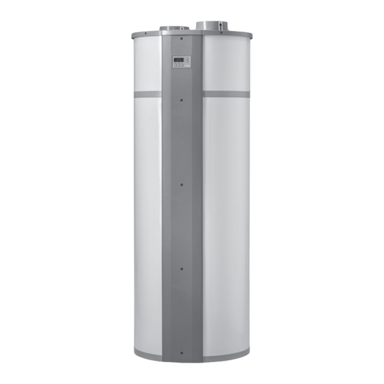
The NIBE MT-WH 2029-F/1FS uses the heat from the extract air to produce hot water. At peak times extra heat can be supplied through an integrated electrical immersion heater of 1.5 kW. -
Page 9: Technical Data
3.5 Technical data Domestic hot water heat pump NIBE MT-WH 2029-F/1FS Diameter without pipe connections Ø660 Height 1837 Weight without water: NIBE MT-WH 2029-F, enamelled Weight without water: NIBE MT-WH 2029-1FS, enamelled Weight without water: NIBE MT-WH 2029-F, stainless Weight without water: NIBE MT-WH 2029-1FS, stainless... -
Page 10: Operating Range / Limits
3 About the product 3.7 Operating range / limits Max./min. extract air temperature °C 35/-5 Max. water temperature (with the heat pump on) °C Max. water temperature (with heat pump and immersion heater on) °C 3.8 Sound level Measuring point 2 meter in front of unit Air volume 100%... -
Page 11: Refrigerant Circuit - Description
3.11 Refrigerant circuit – description The cooling system is optimized for extracting the heat from the inlet air. Via the cooling system the extracted heat is transferred to the water. The process is only possible with the addition of additional external energy in the compressor. The cooling system is a closed system where the HCFC-free refrigerant R134a is the energy carrier. -
Page 12: Water Circuit - Diagram
3 About the product Dirt must be avoided in the pipe system (if necessary flush the pipes before the heat pump is connected)! When no circulation pipe is connected to the heat pump, the circulation connection must be sealed accordingly! 3.12.1 Water circuit - diagram Hot Water Circulation... -
Page 13: Electrical Diagram Optima 170 Control
3.13 Electrical diagram Optima 170 Control Q1=1,6A Q2=5A MA4- Magnetventil afrimning Magnetventile Abtau Magnetic valve Defrost Nettilslutning 1x230V 50Hz sikring max. 13 Amp end main: 1x230V 50Hz fuse mx. 13 Amp Netzende: 1x230V 50Hz 80°C sicherung max 13 Amp El-patron 1,5Kw Electric heating element 1,5Kw Heizstab 1,5Kw Højtrykspressostat... -
Page 14: Fan Capacity
3 About the product 3.14 Fan capacity Fan c apacity Fan capacity 350 300 250 200 150 100 50 0 0 50 100 150 200 250 ... -
Page 15: Before Installation And Start Up
4.1.4 Users The NIBE MT-WH 2029-F/1FS is not intended for use by persons (including children) with re- duced physical, sensory or mental capabilities or lack of experience and knowledge unless they have been given supervision or instruction concerning use of the appliance in a safe way and understand the hazards involved. -
Page 16: Installation
The domestic hot water heat pump must only be installed by trained personel and in accordance with the local building codes. 5.1 Location The NIBE MT-WH 2029-F/1FS must only be installed in a frost-free room. The installation loca- tion should comply with the following criteria: • Room temperature between 5°C and +35°C. - Page 17 4. Removal of unit of from the pallet: 7. Removal of 1st piece of wood (can be released if product is tilted to a: Pull the unit carefully to one side. one side). b: Tilt the unit to the same side together with the 2 pcs. of wood beneath. 8.
-
Page 18: Water Connections
Inlet of fresh cold water is mounted on the bottom connecting branch. 5.5 Connection of condensate drain While the NIBE MT-WH 2029-F/1FS is running, condensate will form, which is to be discharged to the sewage drain via the condensate drain pipe, Ø 19 mm connection outside. The quantity of condensate depends upon the humidity of the air fed to the NIBE MT-WH 2029-F/1FS. -
Page 19: Air Intake, Air Exhaust And Connections
5.7 Connection of NIBE MT-WH 2029-1FS heating coil In the NIBE MT-WH 2029-1FS there is an extra heat exchanger installed (1” coil, 1.2 m²). In the sensor pocket for the thermostat sensor there can also be placed a sensor to control the external Temperatures above 90 °C... -
Page 20: Commissioning
Power up the unit. A counter displays the numbers 1 to 9 followed by display of the controller model (170) for 3 sec. and the software version for 3 sec. Then the top of water tank tempera- ture is displayed and the unit engages operation. The NIBE MT-WH 2029-F/1FS is now ready for use. -
Page 21: Controls And Operations
7 Controls and Operations 7.1 Control panel Optima 170 The NIBE MT-WH 2029-F/1FS domestic hot water heat pump is delivered with an Optima 170 control with factory settings so that the heat pump is ready for operation without additional adjustments. - Page 22 7 Control and Operations P2: Controlling the electrical immersion heater The “immersion heater”-key is pressed and held. Then the setting can be changed with the arrow keys. The heat pump is supplied with an electrical immersion heater for heating of the domestic water. At outside temperatures below 0°C it may be beneficial to use the immersion heater as a sup- plement for heating the domestic water.
-
Page 23: Display View (Main Menu)
7.3.1 Display view (main menu) The display show the various temperatures by pressing the arrow keys. Press until the number of the sensor of the desired temperature appears. After approximately 3 seconds the temperature is displayed. The relevant temperature is displayed for about 30 seconds before the display goes back to normal view. - Page 24 7 Control and Operations E2: T9 temperature set point Here a temperature can be set which can be used in connection with menu item E19 and tem- perature sensor T9. This is a separate sensor, which is not part of standard delivery. See E19=2, 4 or 5 for further description.
- Page 25 E13: Floor heating temperature Here a temperature is set, which can be used in connection with menu item E19=2, i.e., the minimum temperature, at which the circulation pump for the floor heating starts. If the tempera- ture T8 (water tank, bottom) is less than the value set at menu point E13, the circulation pump stops.
- Page 26 Value of 0: This feature is disabled, and the relay is switched off. Value of 1 (special NIBE MT-WH 2029-1FS coil function): The solar collector function which activates an external solar pump (relay R9). If the T8 temperature (water tank, bottom) is lower than the set point in menu point E46 (max.
- Page 27 When the pump (relay R9) is activated, the heat pump and the electrical immersion heater switches off. After the pump (relay R9) is deactivated the following happens after 15 min: • If the T5 temperature (before evaporator) is greater than 5.5 °C, the heat pump is activated. •...
- Page 28 7 Control and Operations E25: Fan speed mode 1 + 2 If extraction of air for a longer period of time is required, mode 2 (P1) can be chosen. The fan will now run, until it is change to a different mode. Enter the speed, at which the fan is to run when mode 2 is chosen.
- Page 29 E32: PV control threshold time The required time (minutes) where the T10 input must be higher than the E31 set point before the heat pump starts in PV mode. This parameter allows filtering of input power and avoidance of heat pump starts on short spikes of excess PV power.
- Page 30 7 Control and Operations E49: Screen saver Here you can select the screen saver: 1: Blank display. A point flashes to show that the system is powered. 2: Water temperature T7 (water tank, top) is displayed. 3: The time is displayed. Options: 1-3 Factory setting: 2 E50: Internal clock hours...
- Page 31 E56: Low tariff period stop time – weekends The stop time of a low electricity tariff period during weekends (day 6-7) is set here. Options: 0-23 hours Factory setting: 6 hours E60: Temperature difference between T5 and T6 If the T6 temperature (evaporator) is higher than the T5 temperature (before evaporator) + the value set in menu point E-0 after one hour with the compressor in operation, the compressor will turn off.
- Page 32 7 Control and Operations 7.5 Table for set points Factory setting Date: Date: E0: Factory settings E2: T9 temperature set point E6: Anti-legionella - week day E7: Anti-legionella – start time E8: Anti-legionella function E9: Operation in cold surroundings ON/OFF E10: Operation in cold surroundings temperature E13: Floor heating temperature E15: Hygrostat / stop system...
-
Page 33: Functional Description
7.6 Table for defrosting T5 before evaporator °C T6 evaporator °C The defrost function runs according to the table for defrosting above. If the T5 temperature (before evaporator) is equal to a temperature in the table then the defrosting will start, if the corresponding T6 temperature (evaporator) drops below the temperature in the table. -
Page 34: Controlling Domestic Hot Water Heat Pump With Optima 170
The unit is used exclusively for heating domestic water within the set temperature limit. Auxiliary function for supplying a small floor heating unit or for alter- native heat input is available in the NIBE MT-WH 2029-F/1FS S model. 7.7.2 Performance The domestic hot water heat pump can heat 367 litres of water from 10 °C to 52.5 °C within... -
Page 35: Extra Heating Capacity
7.7.7 Extra heating capacity If a situation arises where the domestic hot water heat pump is not able to provide enough hot water, it is possible to activate the built-in electrical immersion heater. About twice as much water can now be heated in the same period of time. You can set the temperature to which the electrical immersion heater is to heat the water. - Page 36 7 Control and Operations The call for heating (low water temperatures) can be suppressed during the sunny hours (only allowing for operation on PV power) and released for normal mode operation during user de- fined evening and night times. This is done by the existing low tariff function. The figures below illustrates typical installation options.
-
Page 37: Timer Function
7.7.9 Timer function The timer function includes a 24 hours clock plus week days (1-7). Two different low tariff periods can be defined, working days and weekends. Also, the day and time for anti-legionella control can be set. 7.8 Safety features 7.8.1 High pressure switch In order to ensure that the compressor does not run beyond its operating envelope there is a built-in high pressure switch which shuts down the compressor when the pressure in the cooling... -
Page 38: Maintenance
8 Maintenance To achieve optimal performance, please observe the points below. Before the unit is opened, disconnect the power/ unplug and wait until the fan has stopped. A few days after the initial setup and start-up, check the installation for leaks in the water instal- lation or blockage of the condensate drain. -
Page 39: Anode
8.4.2 Anode In order to prevent corrosion of the enamelled hot water tank, a magnesium anode is installed behind the front panel at the top half of the water tank. The anode has a life expectancy of approximately 2-5 years depending on the water quality. It is recommended to inspect the anode every year. -
Page 40: Disassembly/Decommissioning
The installer, from which the unit was purchased. • After the warranty period (2 years ->): The installer from which the unit was purchased or NIBE Energy Systems Partners. Please have data from name plate ready (silver plate on the unit). -
Page 41: Warranty Provisions
- The product has to be located so that it can be serviced without obstacles. If the product is located in a way that is hard to access, NIBE Energy Systems disclaim all obligations with respect to extra expenses this may cause. -
Page 42: Declaration Of Conformity
12 Declaration of conformity... -
Page 43: Product And Installer Information
13 Product and installer information Installed model: Serial number: Accessories: Installers Pipe installation Date: Company: Name: Phone number: Electrical installation Date: Company: Name: Phone number: Commissioning Date: Company: Name: Phone number:... - Page 44 NIBE AB Sweden Hannabadsvägen 5 Box 14 SE-285 21 Markaryd info@nibe.se www.nibe.eu...
Need help?
Do you have a question about the MT-WH 2029-1FS and is the answer not in the manual?
Questions and answers