Advertisement
Quick Links
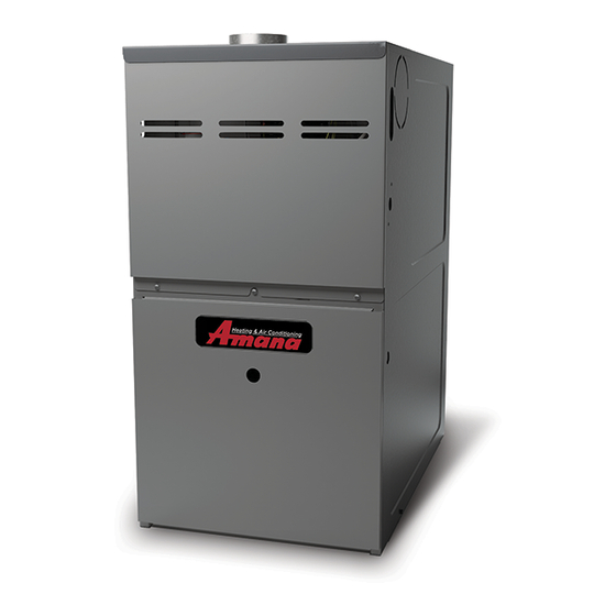
Multi-Speed, Upflow/Horizontal (NOx)
•
Refer to Service Manual RS6610004 for installation, operation, and troubleshooting information.
•
All safety information must be followed as provided in the Service Manual.
•
Refer to the appropriate Parts Catalog for part number information.
•
Model numbers listed on page 3.
This manual is to be used by qualified, professionally trained HVAC technicians only.
Goodman does not assume any responsibility for property damage or personal injury due
to improper service procedures or services performed by an unqualified person.
is a registered trademark of Maytag Corporation or its related companies
®
and is used under license to Goodman Company, L.P., Houston, TX. All rights reserved.
Great user manuals database on
TECHNICAL MANU
TECHNICAL MANU
TECHNICAL MANU
TECHNICAL MANU AL
TECHNICAL MANU
AMH8 33-3/8" 80% Gas Furnace
80% AFUE, Twin Comfort
UserManuals.info
AL
AL
AL
AL
™
,
C
Copyright ©2009-2010 Goodman Company, L.P.
®
US
RT6621017r1
April 2010
Advertisement

Related Manuals for Amana AMH8


Summary of Contents for Amana AMH8
- Page 1 TECHNICAL MANU TECHNICAL MANU TECHNICAL MANU TECHNICAL MANU AL TECHNICAL MANU AMH8 33-3/8" 80% Gas Furnace ™ 80% AFUE, Twin Comfort Multi-Speed, Upflow/Horizontal (NOx) • Refer to Service Manual RS6610004 for installation, operation, and troubleshooting information. • All safety information must be followed as provided in the Service Manual.
- Page 2 PRODUCT FEATURES: MINOR REVISION: N: Natural Gas TYPE: A: Initial Release FURNACE TYPE: ® X: Low NOx A: Amana H: Twin Comfort Brand Multi-Speed CABINET WIDTH: A: 14" C: 21" SUPPLY TYPE: B: 17 1/2" D: 24 1/2" M: Upflow/Horizontal...
- Page 3 PRODUCT IDENTIFICATION The model and manufacturing number are used for positive identification of component parts used in manufacturing. Please use these numbers when requesting service or parts information. AMH80453AXC* AMH80703AXC* AMH80704BXC* AMH80903BXC* AMH80904BXC* AMH80905CXC* AMH81155CXC* AMH81405DXC* * Indicates minor revision & is not used for order entry or inventory management The United States Environmental Protection Agency (“EPA”) has issued various regulations re- WARNING WARNING...
- Page 4 PRODUCT DESIGN General Operation WARNING The AMH8 furnaces are equipped with an electronic ignition device used to light the burners and an induced draft blower to exhaust combustion products. O PREVENT POSSIBLE PERSONAL INJURY OR DEATH DUE TO ASPHYXIATION, THIS FURNACE MUST BE ATEGORY VENTED.
- Page 5 PRODUCT DESIGN Accessibility Clearances (Minimum) High Altitude Derate Unobstructed front clearance of 24" for servicing is rec- When this furnace is installed at high altitude, the appropri- ommended. ate High Altitude orifice kit must be installed. This is re- quired due to the natural reduction in the density of both the gas fuel and combustion air as altitude increases.
- Page 6 COMPONENT IDENTIFICATION Tubular Heat Exchanger Pressure Switch Flue Pipe Connection Induced Draft Blower 躀 Gas Line Entrance Gas Valve Rollout Limit Junction Box Wiring Harness Grommet Gas Manifold Gas Line Entrance (Alternate) Inshot Burner Transformer Circulator Blower Blower Door Interlock Switch Note: Primary Limit Not Shown Integrated Control Module Upflow/Horizontal...
- Page 7 PRODUCT DIMENSIONS AMH8 Alt. Gas Inlet Alt. Gas Inlet Alt. High Voltage High Voltage Inlet Low Voltage Alt. LowVoltage MODELS AMH80453AX** 12-1/2 AMH80703AX** AMH80704BX** AMH80903BX** 17-1/2 AMH80904BX** AMH80905CX** 19-1/2 AMH81155CX** AMH81405DX** 24-1/2 All dimensions are in inches. Great user manuals database on...
- Page 8 -0.70 B1370158 AMH81405DX** -0.75 013070159 AMH81405DX** -0.60 013070142 For installaions in Canada, the AMH8 furnace is certified only to 4,500 ft. * Negative pressure readings are in inches of water column (*w.c.) PRIMARY LIMIT Part Number 0130F00035 20162906 20162903 0130F00036 Open Setting (°F)
- Page 9 A large array of Amana brand coils are available for use with the AMH8 furnaces, in either upflow or horizontal applica- tions. These coils are available in both cased and uncased models (with the option of a field installed TXV expansion ®...
- Page 10 PRODUCT DESIGN Thermostats: The following Amana ® brand Thermostats are suggested for use with the AMH8 Furnace Models: THERMOSTATS Thermostat Mech./Digital Programmable Cool Heat CHT-18-60 Mechanical CH70TG Digital CHSATG Mechanical H20TWR Mechanical Filters: Filters are required with this furnace and must be provided by the installer. The filters used must comply with UL900 or CAN/ULCS111 standards.
- Page 11 PRODUCT DESIGN TwinComfort™ Configuration & Operation TwinComfort™ This furnace is capable of the following heating modes: • Single Stage (Factory Setting) • Modified Two-Stage > Fixed 5-Min. Low Stage > Auto Time (1-12 Min.) Low Stage To change from the factory single-stage operation, adjust the dipswitches on the ignition control as follows: MODE MODE DIP SWITCH...
- Page 12 FURNACE SPECIFICATIONS MODEL Input, Natural Gas (BTUH) 45,000 70,000 70,000 90,000 90,000 90,000 115,000 140,000 36,000 56,000 56,000 72,000 72,000 72,000 92,000 112,000 Output, Natural Gas (BTUH) Output, LP (BTUH) 32,000 48,000 48,000 64,000 64,000 64,000 80,000 96,000 A.F.U.E. 80.0% 80.0% 80.0% 80.0%...
- Page 13 BLOWER PERFORMANCE SPECIFICATIONS (CFM & Temperature Rise vs. External Static Pressure) EXTERNAL STATIC PRESSURE (Inches Water Column) Tons AC Model Motor at 0.5" Heating Speed Speed As Shipped CFM RISE CFM RISE CFM RISE CFM RISE CFM RISE CFM CFM CFM HIGH 1521 1466...
- Page 14 BLOWER PERFORMANCE SPECIFICATIONS Great user manuals database on UserManuals.info...
- Page 15 WIRING DIAGRAMS AMH8_CA/CB WARNING:DISCONNECT POWER BEFORE INTEGRATED HUMIDIFIER CONTROL MODULE SERVICING.WIRING TO UNIT MUST BE PROPERLY POLARIZED AND GROUNDED. XFMR (6) GND (8) 24 VAC MVC (9) HUMIDIFIER VALVE MVH (12) MVL (2) ID BLOWER PRESSURE SWITCH PS (10) 5 MIN 2 STG MODE PSO (4)
- Page 16 WIRING DIAGRAMS AMH8_CC WARNING:DISCONNECT POWER BEFORE HUMIDIFIER INTEGRATED CONTROL MODULE SERVICING.WIRING TO UNIT MUST BE PROPERLY POLARIZED AND GROUNDED. XFMR (6) GND (8) 24 VAC MVC (9) HUMIDIFIER VALVE MVH (12) MVL (2) ID BLOWER PRESSURE AUXILIARY SWITCH LIMIT CONTROLS PS (10) AUTO 5 MIN...
- Page 17 GAS VALVE PRESSURE SWITCH TYPICAL SCHEMATIC AMH8 ____** MODEL FURNACES WR 50M56-289 INTEGRATED IGNITION CONTROL This schematic is for reference only. Not all wiring is as shown above. Always refer to the appropriate wiring diagram for the unit being serviced.
Need help?
Do you have a question about the AMH8 and is the answer not in the manual?
Questions and answers