Table of Contents
Advertisement
Service
Instructions
48" 90% Condensing Gas Furnaces
GUC, GUD, GUX, GCC, GCD, GDC & Accessories
C E R T I F I E D
A IR C O M M A ND
H I E FF IC IE N C Y 9 0 G A S F U RN A C E
®
This manual is to be used by qualified HVAC technicians only. Amana
does not assume any responsibility for property damage or personal injury
due to improper service procedures performed by an unqualified person.
Model and Manufacturing
numbers listed on pages 4 & 5.
A IR C O M M A ND
H I E FF IC IE N C Y 9 0 G A S F U RN A C E
RS6610001
Revision 3
June 2000
Advertisement
Table of Contents

Related Manuals for Amana GUC045B30A


Summary of Contents for Amana GUC045B30A
- Page 1 H I E FF IC IE N C Y 9 0 G A S F U RN A C E C E R T I F I E D ® This manual is to be used by qualified HVAC technicians only. Amana RS6610001 does not assume any responsibility for property damage or personal injury Revision 3 due to improper service procedures performed by an unqualified person.
-
Page 2: Table Of Contents
INDEX Important Safety Information ................... 3 Product Identification ....................4-16 Furnace Specifications .................... 17-29 Blower Performance Specifications ................ 30-35 Combustion and Ventilation Air ................36-49 Product Design ......................50-56 System Operation ....................57-69 Polarization and Phasing..................70 Scheduled Maintenance ..................71-73 Servicing ........................ -
Page 3: Important Safety Information
DANGEROUS CONDITIONS (SUCH AS EXPOSURE TO ELEC- WARNING TRICAL SHOCK) MAY RESULT. THIS MAY CAUSE SERIOUS IN- JURY OR DEATH. AMANA WILL NOT BE RESPONSIBLE FOR ANY INJURY OR CAUTION PROPERTY DAMAGE ARISING FROM IMPROPER SERVICE OR SERVICE PROCEDURES. IF YOU PERFORM SERVICE ON YOUR OWN PRODUCT, YOU ASSUME RESPONSIBILITY FOR ANY PERSONAL INJURY OR PROP- ERTY DAMAGE WHICH MAY RESULT. -
Page 4: Product Identification
It is very important to use the model and manufacturing numbers at all times when requesting service or parts information. MODEL MODEL MODEL MODEL GUC045B30A P9898401F GUC090X35BI P1209404F GUD045C30A P1164501F GUX045X30A P1161707F GUC070B30A P9898402F GUD070C30A P1164502F... - Page 5 PRODUCT IDENTIFICATION The model and manufacturing number are used for positive identification of component parts used in manufacturing. At which time engineering and manufacturing changes take place where interchangeability of components are affected, the manufacturing number will change. It is very important to use the model and manufacturing numbers at all times when requesting service or parts information. FURNACE ACCESSORY KITS ADDITIONAL FURNACE ACCESSORY KITS FFK_...
- Page 6 PRODUCT IDENTIFICATION 045 B Design Series Product Type First Design Series G: Gas Furnace Second Design Series Third Design Series Supply Type U: Upflow Airflow Capability C: Counterflow 25: 2.5 Tons 30: 3.0 Tons D: Counterflow/Horizontal 35: 3.5 Tons 40: 4.0 Tons Furnace Type 50: 5.0 Tons C: Condensing (90% AFUE)
- Page 7 PRODUCT IDENTIFICATION Rev. 3...
- Page 8 PRODUCT IDENTIFICATION Rev. 3...
- Page 9 PRODUCT IDENTIFICATION Rev. 3...
- Page 10 PRODUCT IDENTIFICATION Rev. 3...
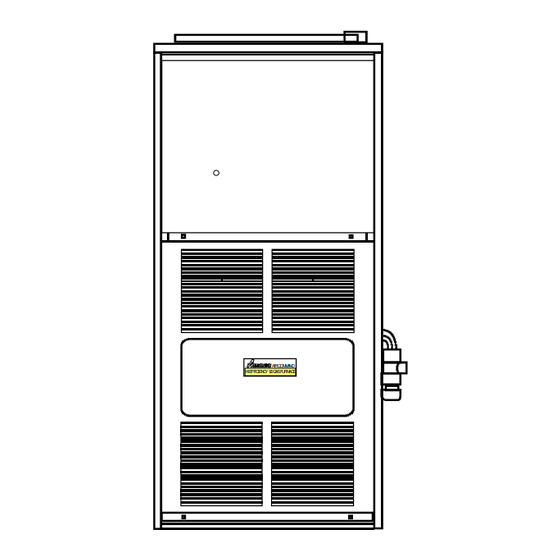
- Page 11 PRODUCT IDENTIFICATION Left Side View Front View 28-1/8 20-1/8 Right Side View 6-5/8 Supply 4-3/4 Supply Supply Electrical Hole Hole-Low Electrical Voltage Hole-Low 1-5/8 ® He a tin g Ai r Con diti o ni n g Voltage Electrical 38-3/4 Hole-Line Voltage Supply...
- Page 12 PRODUCT IDENTIFICATION Top View Combustion Gas Supply Hole Air Inlet Electrical Hole Flue Outlet Line Voltage 4-1/4 1-3/4 4-3/8 1-1/8 2-1/2 Left Side View Front View 28-1/8 20-1/8 Right Side View 2-3/8 6-5/8 Supply 4-3/4 Supply Supply Hole Electrical Electrical Hole-Low 1-5/8 A IR C O M M A N D...
- Page 13 PRODUCT IDENTIFICATION ACCESSORIES 28-1/8" 20-1/4" 3/4" 3/4" 2-3/8" 2" 28-3/4" 38-3/4" 38-1/4" 41-3/8" 41-3/8" 48" 6-5/8" 5-3/8" Electrical Electrical Holes "Low Hole "Low Voltage" Voltage" 1-5/8" A Ra ythe on Compan y Supply Supply Supply 14-7/8" Supply 4-3/4" Supply Hole Hole 6-5/8"...
- Page 14 PRODUCT IDENTIFICATION COUNTERFLOW SUBBASE Sub-Base Gasket Floor 1" Min. Plenum Furnace Front 2" 3/4" 3/4" Plenum Front View 4-7/16" 3/4" Side View Counterflow subbase required when GCC,GCD & GDC furnaces are installed directly on wooden floor. SUBBASE DIMENSIONS SUBBASE USED ON PART MODELS NUMBERS...
-
Page 15: Electronic Air Cleaner
PRODUCT IDENTIFICATION ACCESSORIES MEDIA AIR CLEANER MAC1 SPECIFICATIONS CAPACITY 600-2000CFM MEDIA SERVICE LIFE 12 MO.NOMINAL MEDIA LISTING UL CLASS 2 DIMENSIONS 7-1/4 22-1/8 22-5/8 17-11/16 RESISTANCE INCHES W.C. 1000 1200 1400 1600 1800 2000 All dimensions are in inches. MEDIA AIR CLEANER USED ON MODELS ALL GAS FURNACES ELECTRONIC AIR CLEANER... - Page 16 PRODUCT IDENTIFICATION ACCESSORIES EXTERNAL FILTER RACK KIT 23.567 SLOTS IN FILTER CLEAR SCREWS ON UNIT BLOWER DECK SCREWS 14.500 UNIT SIDE PANEL FRONT OF UNIT EFR01 EXTERNAL FILTER RACK KIT USED ON MODELS FILTER RACK ASSEMBLY (FACE FILTER OPENING BASE TOWARDS FRONT OF UNIT OF UNIT)
-
Page 17: Furnace Specifications
FURNACE SPECIFICATIONS GUC045B30A GUC070B30A GUC070B40A GUC090B35A GUC090B50A GUC115B50A MODEL GUC045B30B GUC070B30B GUC070B40B GUC090B35B GUC090B50B GUC115B50B Btuh Input (US) 45,000 70,000 70,000 90,000 90,000 115,000 Output (US) 43,000 65,000 65,000 83,000 84,000 107,000 Input (CAN) 45,000 70,000 70,000 90,000 90,000 115,000... - Page 18 FURNACE SPECIFICATIONS MODEL GUC045B30C GUC070B30C GUC070B40C GUC090B35C GUC090B50C GUC115B50C Btuh Input (US) 45,000 70,000 70,000 90,000 90,000 115,000 Output (US) 43,000 65,000 65,000 83,000 84,000 107,000 Input (CAN) 45,000 70,000 70,000 90,000 90,000 115,000 Output (CAN) 43,400 66,400 66,400 85,700 85,700 107,500 High Alt Input (CAN)
- Page 19 FURNACE SPECIFICATIONS GUC045C30C GUC070C30C GUC070C40C GUC090C35C GUC090C50C GUC115C50C MODEL GUC045X30A GUC070X30A GUC070X40A GUC090X35A GUC090X50A GUC115X50A Btuh Input (US) 45,000 70,000 70,000 90,000 90,000 115,000 Output (US) 43,000 65,000 65,000 83,000 84,000 107,000 Input (CAN) 45,000 70,000 70,000 90,000 90,000 115,000 Output (CAN) 43,400 66,400...
- Page 20 FURNACE SPECIFICATIONS MODEL GUC045X30B GUC070X30B GUC070X40B GUC090X35B GUC090X50B GUC115X50B Btuh Input (US) 45,000 70,000 70,000 90,000 90,000 115,000 Output (US) 42,900 65,300 65,300 85,000 85,000 107,800 Input (CAN) 45,000 70,000 70,000 90,000 90,000 115,000 Output (CAN) 43,400 66,400 66,400 85,700 85,700 107,500 High Alt Input (CAN)
- Page 21 FURNACE SPECIFICATIONS GCC045B30A GCC070B30A GCC070B40A GCC090B40A GCC090B50A GCC115B50A MODEL GCC045B30B GCC070B30B GCC070B40B GCC090B40B GCC090B50B GCC115B50B Btuh Input (US) 45,000 70,000 70,000 90,000 90,000 115,000 Output (US) 42,000 65,000 65,000 84,000 84,000 106,000 Input (CAN) 45,000 70,000 70,000 90,000 90,000 115,000 Output (CAN) 42,000 65,000...
- Page 22 FURNACE SPECIFICATIONS GCC045C30C GCC070C30C GCC070C40C GCC090C35C GCC090C50C GCC115C50C MODEL GCC045X30A GCC070X30A GCC070X40A GCC090X35A GCC090X50A GCC115X50A Btuh Input (US) 45,000 70,000 70,000 90,000 90,000 115,000 Output (US) 43,000 65,000 66,000 84,000 84,000 105,000 Input (CAN) 45,000 70,000 70,000 90,000 90,000 115,000 Output (CAN) 43,000 67,000...
- Page 23 FURNACE SPECIFICATIONS MODEL GUD045B30A GUD070B30A GUD070B40A GUD090B35A GUD090B50A GUD115B50A Btuh Input (US) 45,000 70,000 70,000 90,000 90,000 115,000 Output (US) 43,000 65,000 65,000 83,000 84,000 107,000 Input (CAN) 45,000 70,000 70,000 90,000 90,000 115,000 Output (CAN) 43,400 66,400 66,400 85,700 85,700 107,500 High Alt Input (CAN)
- Page 24 FURNACE SPECIFICATIONS GUD045C30A GUD070C30A GUD070C40A GUD090C35A GUD090C50A GUD115C50A MODEL GUD045X30A GUD070X30A GUD070X40A GUD090X35A GUD090X50A GUD115X50A Btuh Input (US) 45,000 70,000 70,000 90,000 90,000 115,000 Output (US) 43,000 65,000 65,000 84,000 84,000 107,000 Input (CAN) 45,000 70,000 70,000 90,000 90,000 115,000 Output (CAN) 43,700 66,400...
- Page 25 FURNACE SPECIFICATIONS MODEL GUD045X30B GUD070X30B GUD070X40B GUD090X35B GUD090X50B GUD115X50B Btuh Input (US) 45,000 70,000 70,000 90,000 90,000 115,000 Output (US) 43,000 65,700 65,700 84,300 85,100 107,600 Input (CAN) 45,000 70,000 70,000 90,000 90,000 115,000 Output (CAN) 43,000 65,700 65,700 85,000 85,100 107,600 High Alt Input (CAN)
- Page 26 FURNACE SPECIFICATIONS GUX045B30A GUX070B30A GUX070B40A GUX090B35A GUX090B50A GUX115B50A MODEL GUX045X30A GUX070X30A GUX070X40A GUX090X35A GUX090X50A GUX115X50A Btuh Input (US) 45,000 70,000 70,000 90,000 90,000 115,000 Output (US) 43,600 67,000 67,000 86,000 87,000 110,000 Input (CAN) 45,000 70,000 70,000 90,000 90,000 115,000 Output (CAN) 43,400 67,600...
- Page 27 FURNACE SPECIFICATIONS MODEL GUX045X30B GUX070X30B GUX070X40B GUX090X35B GUX090X50B GUX115X50B Btuh Input (US) 45,000 70,000 70,000 90,000 90,000 115,000 Output (US) 43,600 67,100 67,100 86,200 86,200 109,600 Input (CAN) 45,000 70,000 70,000 90,000 90,000 115,000 Output (CAN) 43,600 67,100 67,100 86,200 96,200 109,600 High Alt Input (CAN)
- Page 28 FURNACE SPECIFICATIONS MODEL GDC045X30B GDC070X30B GDC070X40B GDC090X40B GDC090X50B GDC115X50B Btuh Input (US) 46,000 69,000 69,000 92,000 92,000 115,000 Output (US) 43,300 65,600 65,500 87,000 87,200 107,700 Input (CAN) 46,000 69,000 69,000 92,000 92,000 115,000 Output (CAN) 43,100 65,000 65,000 86,700 86,700 107,200 High Alt Input (CAN)
- Page 29 FURNACE SPECIFICATIONS MODEL GCD070X30B GCD090X40B Btuh Input (US) 69,000 92,000 Output (US) 64,700 85,900 Input (CAN) 69,000 92,000 Output (CAN) 64,300 86,700 High Alt Input (CAN) 62,100 82,800 Output (CAN) 58,500 78,000 A.F.U.E. 93.6% 94.0% Rated External Static ("w.c.) .12 - .50 .15 - .50 Temperature Rise (°F) 35 - 65...
-
Page 30: Blower Performance Specifications
BLOWER PERFORMANCE SPECIFICATIONS TONS AC External Static Pressure, Inches Water Column MOTOR MODEL @ 0.5" SPEED CFM Rise CFM Rise CFM Rise CFM Rise CFM Rise CFM Rise CFM Rise HIGH 1500 1440 1375 1295 1210 1120 1010 GUC045_30_ 1275 1200 1175 1125... - Page 31 BLOWER PERFORMANCE SPECIFICATIONS TONS AC External Static Pressure, Inches Water Column MOTOR MODEL @ 0.5" SPEED CFM Rise CFM Rise CFM Rise CFM Rise CFM Rise CFM Rise CFM Rise HIGH 1480 1425 1365 1300 1210 1110 GCC045_30_ 1265 1225 1175 1125 1050...
- Page 32 BLOWER PERFORMANCE SPECIFICATIONS TONS AC External Static Pressure, Inches Water Column MOTOR MODEL @ 0.5" SPEED CFM Rise CFM Rise CFM Rise CFM Rise CFM Rise CFM Rise CFM Rise HIGH 1500 1440 1375 1295 1210 1120 1010 GUD045_30A 1275 1200 1175 1125...
- Page 33 BLOWER PERFORMANCE SPECIFICATIONS TONS AC External Static Pressure, Inches Water Column MOTOR MODEL @ 0.5" SPEED CFM Rise CFM Rise CFM Rise CFM Rise CFM Rise CFM Rise CFM Rise HIGH 1525 1455 1390 1325 1245 1180 1090 GUX045_30_ 1230 1200 1160 1125...
- Page 34 BLOWER PERFORMANCE SPECIFICATIONS MODEL TONS AC External Static Pressure, Inches Water Column MOTOR (Htg. Speed @ 0.5" SPEED As Shipped) CFM Rise CFM Rise CFM Rise CFM Rise CFM Rise CFM CFM CFM HIGH 1596 1533 1467 1398 1310 1233 1150 1032 GDC045X30B...
- Page 35 BTU OUTPUT vs TEMPERATURE RISE CHART 600 CFM 1000 1100 1200 1400 1600 1800 2000 2200 2400 CFM FORMULAS BTU OUTPUT = CFM x 1.08 x RISE BTU OUTPUT RISE = ÷ CFM 1.08 OUTPUT BTU/HR x 1000...
-
Page 36: Combustion And Ventilation Air
COMBUSTION AND VENTILATION AIR (All Except GUD/GCD Direct Vent Models) (e) A draft hood or a barometric draft regulator shall be installed in WARNING the same room as the equipment served so as to prevent any difference in pressure between the hood or regulator and the Possible death, personal injury or property damage may combustion air supply. - Page 37 COMBUSTION AND VENTILATION AIR (All Except GUD/GCD Direct Vent Models) (b) All Air from Outdoors: The confined space shall communicate 3. When communicating with the outdoors through horizontal with the outdoors in accordance with one of the following two ducts, each opening shall have a minimum free area of 1 methods: Two permanent openings, one commencing within square inch per 2,000 BTU per hour of total input rating of 12 inches of the top and one commencing within 12 inches of...
- Page 38 FAILURE TO FOLLOW THESE INSTRUCTIONS CAN RE- furnace. Amana Heating & Air Conditioning does not en- SULT IN BODILY INJURY OR DEATH FROM ASPHYXI- courage nor recommend using these connectors. However, ATION.
- Page 39 COMBUSTION AND VENTILATION AIR (All Except GUD/GCD Direct Vent Models) VENT PIPING - GUC/GCC/GDC/GUX (ALL INSTALLA- This is greater than the 52 equivalent feet which is allowed. TIONS), AND GUD/GCD (ONE PIPE SYSTEM) 3" pipe has only 1/3 the pressure drop of 2" pipe. Changing a portion of the piping to 3"...
- Page 40 COMBUSTION AND VENTILATION AIR (All Except GUD/GCD Direct Vent Models) The following expanded venting tables are for the GUC___X__B, GUD___X__B, GUX___X__B, GDC___X__B and GCD___X__B model furnaces only. These venting tables allow applications with up to eight (8) 90° medium radius elbows and a maximum length greater than 40 feet for some models.
- Page 41 COMBUSTION AND VENTILATION AIR (All Except GUD/GCD Direct Vent Models) When venting pipe goes through an outside wall, the need to be increased. The vent must be made tight where vent must terminate at least one foot outside to keep moist it penetrates the roof with a proper flashing such as used combustion products away from the structure.
- Page 42 COMBUSTION AND VENTILATION AIR (All Except GUD/GCD Direct Vent Models) Cut all vent pipe at right angles. Remove inside and out- WARNING side burr at each cut. Use cleaner to clean pipe and fitting socket. Use CSA listed cement to fasten pipe and fittings. UPON COMPLETION OF THE FURNACE INSTALLA- Follow manufacturers cleaning and cementing instructions TION, CAREFULLY INSPECT THE ENTIRE FLUE SYS-...
- Page 43 COMBUSTION AND VENTILATION AIR (GUD/GCD Direct Vent Models) COMBUSTION AIR AND VENT PIPING (GUD/GCD DI- restriction, leakage, corrosion and other deficiencies, RECT VENT (TWO PIPE SYSTEM)) which could cause an unsafe condition. General Information and Safety Precautions c. Insofar as is practical, close all building doors and win- dows and all doors between the space in which the ap- pliances remaining connected to the common venting WARNING...
- Page 44 Amana Heating & Air Conditioning does eration of regulators, relief valves, or other equipment. not encourage nor recommend using these connectors.
- Page 45 COMBUSTION AND VENTILATION AIR (GUD/GCD Direct Vent Models) 2. Horizontal Vent/Intake Terminations DO NOT point terminals into window wells, stairwells, alcoves, or other recessed areas. It is preferable for the air intake to terminate on opposite or adjacent sides of the structure from the dryer vent.
- Page 46 COMBUSTION AND VENTILATION AIR (GUD/GCD Direct Vent Models) SIZING OF EXHAUST VENT AND COMBUSTION AIR 2-90° ELBOWS INLET PIPES MEDIUM RADIUS Consult the following direct vent piping charts to select the 12" proper diameter exhaust and combustion air piping. The vent and air intake piping is sized for each unit model num- VENT/FLUE ber based on total line length and number of 90°...
-
Page 47: Vent Pipe Installation
COMBUSTION AND VENTILATION AIR (GUD/GCD Direct Vent Models) VENT PIPE INSTALLATION The horizontal run of exhaust pipe must not have any sag that can hold condensate and should pitch up at least 1/4" 1. Horizontal or Vertical per foot so that condensate will run back to the unit to drain. The size of the vent and air intake pipes is determined by Support the horizontal run at least every three feet. - Page 48 COMBUSTION AND VENTILATION AIR (GUD/GCD Direct Vent Models) The following four venting tables on this page are for the earlier GUD direct vent (two pipe system) model furnaces only. These venting tables allow applications with up to six (6) 90° medium radius elbows and a maximum length of 40 feet. The furnace models that utilize these expanded tables are listed at the top of each table.
- Page 49 COMBUSTION AND VENTILATION AIR (GUD/GCD Direct Vent Models) Vent and Combustion Air Pipe Diameter for GUD090X__B Direct Vent (Two Pipe System) Inside Feet of Straight Pipe # of Vent Inside 5 to 10 10 to 15 15 to 20 20 to 25 25 to 30 30 to 35 35 to 40...
-
Page 50: Product Design
PRODUCT DESIGN CONDENSATE DRAIN The minimum supply pressure must not be varied down- ward because this could lead to unreliable ignition. In addi- The Air Command 90 and 95 achieves its high efficiency tion, gas input to the burners must not exceed the rated by condensing some of the flue products into a slightly acidic input shown on the rating plate. - Page 51 PRODUCT DESIGN CHECKING THE GAS PIPING Natural Gas Capacity of Pipe In Cubic Feet of Gas Per Hour (CFH) Length of Nominal Black Pipe Size CAUTION Pipe in Feet 1/2" 3/4" 1" 1 1/4" 1 1/2" 1050 1600 1100 TO AVOID THE POSSIBILITY OF PROPERTY DAMAGE, PERSONAL INJURY OR FIRE, THE FOLLOWING IN- STRUCTIONS MUST BE PERFORMED REGARDING GAS CONNECTIONS AND PRESSURE TESTING.
- Page 52 PRODUCT DESIGN 3. Pressure drop in lines between regulators, and between PROPANE PIPING AND TANK SIZING CHARTS second stage regulator and the appliance. Pipe size re- Sizing Between First and Second Stage Regulator* quired will depend on length of pipe run and total load Maximum Propane Capacities listed are based on 2 psig pressure drop at 10 psig setting.
- Page 53 PRODUCT DESIGN ELECTRICAL WIRING CONTROL MODULE Hot 120 VAC Neutral 120 VAC WARNING TO AVOID THE RISK OF ELECTRICAL SHOCK, WIR- ING OF THE UNIT MUST BE PROPERLY POLARIZED AND GROUNDED. WARNING AIR CLEANER OPTIONAL ACCESSORIES TO AVOID ELECTRICAL SHOCK, INJURY OR DEATH, HUMIDIFIER DISCONNECT ELECTRICAL POWER BEFORE CHANG- Accessory Wiring...
- Page 54 PRODUCT DESIGN Thermostat Requirements Style B Style A The following drawing illustrates the typical field wiring for a heat only single stage system and a single stage heating/ Second Delay single stage cooling system. Heating Heating/Cooling Room Second Room Delay Thermostat Thermostat Second...
- Page 55 PRODUCT DESIGN GUC, GUD, GUX Upflow Installations Bottom Return Filter Sizes Furnace Model Permanent (Qty), Size Disposable (Qty), Size Return Air 045_30 (1) 14x25x1 (2) 16x20x1 070_30 (1) 16x25x1 (2) 16x20x1 070_40 (1) 16x25x1 (2) 16x20x1 Optional (See Tables Access 090_35 (1) 20x25x1 (2) 20x20x1...
- Page 56 PRODUCT DESIGN If preferred, external filter grilles may be used in place of A closed return duct system must be used, with the return the filters discussed above. If this is done, refer to the fol- duct connected to the furnace. Note: Ductwork must never be attached to the back of the furnace.
-
Page 57: System Operation
SYSTEM OPERATION NORMAL SEQUENCE OF OPERATION SELF DIAGNOSTIC IGNITION CONTROL (Models with White Rodgers 50E47-170 Control) In this furnace, there may be a red indicator light located on the ignition control board near the MV terminal. This light is 1. Thermostat calls for heat. The induced draft blower is designed to help the servicer diagnose potential service immediately energized. -
Page 58: Normal Sequence Of Operation
SYSTEM OPERATION NORMAL SEQUENCE OF OPERATION Cooling Mode The normal operational sequence in cooling mode is as (Models with White-Rodgers 50A50-205, 206, 288 or 298 follows: & 50A60-288 Integrated Ignition Control) 1. R and Y thermostat contacts close, initiating a call for Power Up cool. - Page 59 SYSTEM OPERATION HEATING TIMING CHART FOR WHITE-RODGERS 50A50-205, 206, 288 or 298 & 50A60-288 INTEGRATED IGNITION CONTROL OPERATION AIR CIRCULATION BLOWER OPEN GAS VALVE CLOSED IGNITOR CLOSED PRESSURE SWITCH OPEN INDUCED DRAFT BLOWER THERMOSTAT SECONDS 17 21 Cooling Timing Chart for White-Rodgers 50E47-170 and 50A50-205, 206, 288 or 298 and 50A60-288 Ignition Control Operation Indoor Fan Outdoor Fan...
-
Page 60: Abnormal Operation
SYSTEM OPERATION ABNORMAL OPERATION 4. Pressure Switch Stuck Open (Models with White-Rodgers 50A50-205, 206 or 298 In- If, after the induced draft blower is energized, the pres- tegrated Ignition Control) sure switch does not close, the control will keep the blower on and wait for the switch to close. - Page 61 SYSTEM OPERATION ABNORMAL OPERATION 3. Pressure Switch Stuck Closed. If the control senses the pressure switch is closed when the induced draft (Models with White-Rodgers 50A50-288 or 50A60-288 blower is off, it waits until the fault is corrected. The Integrated Ignition Control) diagnostic light code for this problem is two short The following presents the probable causes of question- flashes followed by a longer pause.
- Page 62 SYSTEM OPERATION NORMAL SEQUENCE OF OPERATION Cooling Mode The normal operational sequence in cooling mode is as (Models with White-Rodgers 50A55-288 Integrated Ig- follows: nition Control) 1. R and Y thermostat contacts close, initiating a call for Power Up cool. The normal power up sequence is as follows: 2.
- Page 63 SYSTEM OPERATION HEATING TIMING CHART FOR WHITE-RODGERS 50A55-288 INTEGRATED IGNITION CONTROL OPERATION CIRCULATOR BLOWER OPEN GAS VALVE CLOSED IGNITER CLOSED PRESSURE SWITCH OPEN CONTACTS INDUCED DRAFT BLOWER THERMOSTAT 60,90, SECONDS circ 120 or IGNITER FIXED HEAT WARM UP PERIOD ON DELAY: (see note) 30 SECONDS NOTE: WHITE-RODGERS INTEGRATED CONTROL MODULE HAS A...
- Page 64 SYSTEM OPERATION ABNORMAL OPERATION 5. Open Primary or Auxiliary Limit. If the limit control opens, the air circulation and induced draft blower will (Models with White-Rodgers 50A55-288 Integrated Ig- be turned on until the limit closes. The diagnostic light nition Control) code for this problem is four short flashes followed by The following presents the probable causes of question- a pause.
- Page 65 Troubleshooting Chart for White-Rodgers 50A55-288 Integrated Ignition Control Symptoms of Associated Cautions and Abnormal LED Code Fault Description(s) Possible Causes Corrective Action Notes Operation (See Note 2) - Furnace fails to operate. - Assure 115 V and 24 V power to furnace and integrated control - No 115 V power to furnace, or no 24 V - Manual disconnect switch OFF, door switch open, - Turn power OFF prior to repair.
- Page 66 Troubleshooting Chart for White-Rodgers 50A55-288 Integrated Ignition Control Associated Symptoms of Abnormal Cautions and LED Code Fault Description(s) Possible Causes Corrective Action Operation Notes (See Note 2) - Furnace fails to operate. - Polarity of 115 V AC power to furnace or integrated control module is reversed.
-
Page 67: Heating Cycle
SYSTEM OPERATION HEATING CYCLE In order to illustrate the heating sequence using a induced SWITCH draft blower, the following has been simplified to give a bet- HOSE TO NC NO INDUCED DRAFT ter understanding of the pressure switch operation. BLOWER HOUSING DIAPHRAGM PRESSURE CHAMBER GUC, GCC, GUX &... - Page 68 SYSTEM OPERATION OPERATING INSTRUCTIONS Pressure Regulator Outlet (Manifold) Adjustment 1. Close the manual gas valve external to the furnace. Pressure Tap (Under Cap Screw) Honeywell 2. Turn off the electrical power supply to the furnace. 3. Set room thermostat to lowest possible setting. 4.
- Page 69 SYSTEM OPERATION Outlet (Manifold)Pressure Tap Gas Valve (Side of Valve) On/Off Control Lever Outlet (Manifold) Pressure Tap (Side of Valve) INLET OUTLET INLET OUTLET Pressure Regulator Gas Valve Pressure Regulator Adjustment Inlet Pressure Tap On/Off Adjustment Inlet Pressure Tap (Under Cap Screw) (Side of Valve) Control Lever (Under Cap Screw)
-
Page 70: Polarization And Phasing
POLARIZATION AND PHASING As more and more electronic's are introduced to the Heat- Incoming Power ing Trade, Polarization of incoming power and phasing of Reads Reads 120 Volts 0 Volts primary to secondary voltage on transformers becomes more important. Polarization has been apparent in the Appliance industry V O LT / OH M V O LT / OH M M ET ER... -
Page 71: Air Filter
MAINTENANCE Grasp the lower portion of the filter, lift up to disengage it WARNING from the lower railing, move towards blower, drop filter down. Pull filter outward. Refer to the filter removal drawing be- TO AVOID ELECTRICAL SHOCK, INJURY OR DEATH, low. - Page 72 MAINTENANCE Clean, wash, and dry the permanent filter. Both sides should SEALED COMBUSTION CHAMBER - GUD then be sprayed with a dust adhesive as recommended on (QUALIFIED SERVICER ONLY) adhesive container. Reinstall filter by placing it into the fur- To inspect the combustion chamber at the start of each nace along the side of the blower.
-
Page 73: Flame Sensor (Qualified Servicer Only)
MAINTENANCE 7. The primary heat exchanger tubes can be cleaned us- BURNERS ing a round wire brush attached to a length of high grade stainless steel cable, such as drain cleanout cable. At- WARNING tach a variable speed reversible drill to the other end of Electrical components are contained in both compart- the spring cable. -
Page 74: Test Equipment
SERVICING TEST EQUIPMENT Multiplying the ninety (90) cubic feet by 1025 BTU gives us an input of 92,250 BTUH. Proper test equipment for accurate diagnosis is as essen- tial as regulator hand tools. Checking the BTU input on the rating plate of the furnace being tested. -
Page 75: Gas Rate -- Cubic Feet Per Hour
SERVICING 1 Thousand 1 Million 10 Thousand 100 Thousand CUBIC Quarter FEET Foot Foot GAS RATE -- CUBIC FEET PER HOUR Size of Test Dial Size of Test Dial Seconds for Seconds for cu/ft cu/ft cu/ft cu/ft cu/ft cu/ft cu/ft cu/ft cu/ft cu/ft... - Page 76 SERVICING Complaint No Heat Unsatisfactory Heat POSSIBLE CAUSE Test Method DOTS IN ANALYSIS Remedy GUIDE INDICATE "POSSIBLE CAUSE" • Power Failure Test Voltage • Blown Fuse Test Voltage • Loose Connection Check Wiring • Shorted or Broken Wires Check Wiring •...
- Page 77 SERVICING SERVICING SECTION INDEX S-1 Checking Voltage S-2 Checking Wiring S-3 Checking Thermostat, Wiring, and Anticipator 78-79 S-4 Checking Transformer and Control Circuit S-5 Checking Fan Relay (A/C Models) S-6 Checking Combination Fan and Limit Control 79-80 S-6A Checking Primary Limit Control S-7 Checking Auxiliary Limit Control S-8 Checking Air Circulation Blower Motor or Induced Draft Blower Motor...
-
Page 78: Checking Voltage
SERVICING S-1 CHECKING VOLTAGE With Power ON: Disconnect Electrical Power Supply: WARNING 1. Remove access door from furnace to gain entry to Junc- LINE VOLTAGE NOW PRESENT. tion Box. Combustion I.D. Motor must run. 2. Remove cover from Junction Box and gain access to incoming power lines. -
Page 79: Checking Transformer And Control Circuit
SERVICING 3-C Cooling Anticipator The cooling anticipator is a small heater (resistor) in the thermostat. During the "OFF" cycle it heats the bimetal ele- ment helping the thermostat call for the next cooling cycle. This prevents the room temperature from rising too high Volt / Ohm before the system is restarted. -
Page 80: Checking Auxiliary Limit Control
SERVICING Depending on the individual type of furnace (upflow, coun- terflow, etc.) will determine as to what the cutout point set- ting of the control will be. Refer to the chart on page 81 for temperature settings. In all instances the limit control is wired in series with the Volt / Ohm ignition control. - Page 81 SERVICING Honeywell Combination Fan/Limit Part # M0352917 M0352918 M0352919 M0352920 M0352921 Open Setting (°F) Model # Mfg # GUC045B30A P9898401F GUC070B30A P9898402F GUC070B40A P9898403F GUC090B35A P9898404F GUC090B50A P9898405F GUC115B50A P9898406F GUC045B30B P1106901F GUC070B30B P1106902F GUC070B40B P1106903F GUC090B35B P1106904F GUC090B50B P1106905F...
- Page 82 SERVICING T.O.D. PRIMARY LIMIT Part Number 10250801 10250802 10250803 10250804 10250805 10250806 10250807 10250808 10250815 Open Setting (°F) Sleeve Colors Brown Orange Green Blue Yellow Black White Sleeve Colors Brown Orange Green Blue Yellow Black White Green GUC045_30_ GUC070_30_ GUC070_40_ GUC090_35_ GUC090_50_ GUC115_50_...
-
Page 83: Checking Capacitor
SERVICING S-9A Resistance Check AUXILLARY LIMIT SWITCHES PART NUMBER M0352005 OPEN SETTING (°F) GCC___B__A GCC___B__B GCC___C__C Volt / Ohm GCC___X__A Meter GDC___X__B GCD___X__B S-8 CHECKING AIR CIRCULATOR BLOWER MO- TOR OR INDUCED DRAFT BLOWER MOTOR WARNING Testing Capacitor Resistance Disconnect Electrical Power Supply: WARNING 1. -
Page 84: Checking Gas Valve (Redundant)
SERVICING S-10 CHECKING GAS VALVE (Redundant) A combination redundant operator type gas valve which provides all manual and automatic control functions required for gas fired heating equipment is used. The valve provides control of main burner gas flow, pres- sure regulation, and 100 percent safety shut-off. With Power OFF: 1. -
Page 85: Checking Gas Pressure
SERVICING GAS LINE GAS SHUTOFF VALVE STREAM B GAS LINE TO FURNACE OPEN TO The length of Dimension "A" determines included angle of ATMOSPHERE Spray "B". DRIP LEG CAP WITH FITTING DENT OR BURR MANOMETER HOSE STREAM B MANOMETER A dent of burr will cause severe deflection of gas stream. Measuring Inlet Gas Pressure GAS VALVE CONTROL S-13 CHECKING GAS PRESSURE... -
Page 86: Checking For Delayed Ignition
SERVICING To properly adjust manifold gas pressure on either the GUD S-16 CHECKING DUCT STATIC or GCD Direct Vent furnace the negative side of the ma- The maximum and minimum allowable external static pres- nometer must be connected to the gas valve vent tap hose. sures are found in the blower performance specification Failure to connect both sides of the manometer as shown section on pages 30-34. -
Page 87: Checking Temperature Rise
SERVICING S-17 CHECKING TEMPERATURE RISE S-18 CHECKING PRESSURE CONTROL Temperature rise is related to the BTUH output of the fur- A pressure control device is used to measure negative pres- nace and the amount of air (CFM) circulated over the heat sure at the induced draft blower motor inlet to detect a par- exchanger. - Page 88 SERVICING PRESSURE SWITCH TRIP POINTS AND USAGE CHART MIN. NEG. MIN. NEG. MAX. NEG. PRESSURE SWITCH TRIP POINTS AND USAGE PRESSURE PRESSURE PRESSURE WITH FLUE WITH FLUE 0 to 4000 ft. 4001 to 7000 ft. 7001 to 10000 ft. AIR BOX MODEL # NOT FIRING FIRING...
- Page 89 SERVICING PRESSURE SWITCH TRIP POINTS AND USAGE CHART MIN. NEG. MIN. NEG. MAX. NEG. PRESSURE SWITCH TRIP POINTS AND USAGE PRESSURE PRESSURE PRESSURE WITH FLUE WITH FLUE 0 to 4000 ft. 4001 to 7000 ft. 7001 to 10000 ft. AIR BOX MODEL # NOT FIRING FIRING...
- Page 90 SERVICING PRESSURE SWITCH TRIP POINTS AND USAGE CHART MIN. NEG. MIN. NEG. MIN. NEG. MIN. NEG. PRESSURE SWITCH TRIP POINTS AND USAGE PRESSURE PRESSURE PRESSURE PRESSURE WITH FLUE WITH FLUE COIL COVER COIL COVER 0 to 4000 ft. 4001 to 7000 ft. 7001 to 10000 ft.
-
Page 91: High Altitude Application (Usa)
SERVICING With Power ON: WARNING WARNING PROPANE CONVERSION AND HIGH ALTITUDE KITS CAN NOT BE USED WITH THE GUD-B MODEL FUR- LINE VOLTAGE NOW PRESENT. NACE. TO DO SO WILL RESULT IN UNSATISFACTORY 4. Energize furnace for heating cycle. The combustion re- FURNACE OPERATION, AND THE POSSIBILITY OF lay should be energized and the induced draft blower PROPERTY DAMAGE, PERSONAL INJURY OR FIRE. - Page 92 SERVICING 4. If above tests are not completed within the prescribed WARNING time limit, the control will retry two more times. How- ever, you will have a 60 second delay before the next LINE VOLTAGE NOW PRESENT. try and your preheat time will be increased to 55 sec- 5.
- Page 93 Early production White-Rodgers (WH) wire to the heat terminal on the ignition control. 50E47 controls Amana Part # C6411101 prior to 8731 No voltage - replace ignition control. date code on the control will have 1.5 to 6 micro-amps.
- Page 94 SERVICING S-23 CHECKING FLAME ROLLOUT SWITCH This control is wired is series with the gas valve. The con- trol is designed to open should a flame roll out occur. An The protection device is located on the manifold assembly over firing condition or flame impingement on the heat shield on GUC, GCC, GDC and GUX models (Refer to the follow- may also cause the control to open.
-
Page 95: Wiring Diagrams
TO AVOID POSSIBLE ELECTRICAL SHOCK, PERSONAL INJURY, WARNING OR DEATH, DISCONNECT THE POWER BEFORE SERVICING. - Page 96 TO AVOID POSSIBLE ELECTRICAL SHOCK, PERSONAL INJURY, WARNING OR DEATH, DISCONNECT THE POWER BEFORE SERVICING.
- Page 97 TO AVOID POSSIBLE ELECTRICAL SHOCK, PERSONAL INJURY, WARNING OR DEATH, DISCONNECT THE POWER BEFORE SERVICING.
- Page 98 TO AVOID POSSIBLE ELECTRICAL SHOCK, PERSONAL INJURY, WARNING OR DEATH, DISCONNECT THE POWER BEFORE SERVICING.
- Page 99 TO AVOID POSSIBLE ELECTRICAL SHOCK, PERSONAL INJURY, WARNING OR DEATH, DISCONNECT THE POWER BEFORE SERVICING.
- Page 100 TO AVOID POSSIBLE ELECTRICAL SHOCK, PERSONAL INJURY, WARNING OR DEATH, DISCONNECT THE POWER BEFORE SERVICING.
- Page 101 TO AVOID POSSIBLE ELECTRICAL SHOCK, PERSONAL INJURY, WARNING OR DEATH, DISCONNECT THE POWER BEFORE SERVICING.
- Page 102 TO AVOID POSSIBLE ELECTRICAL SHOCK, PERSONAL INJURY, WARNING OR DEATH, DISCONNECT THE POWER BEFORE SERVICING.
- Page 103 TO AVOID POSSIBLE ELECTRICAL SHOCK, PERSONAL INJURY, WARNING OR DEATH, DISCONNECT THE POWER BEFORE SERVICING.
- Page 104 1. SET HEAT ANTICIPATOR ON ROOM THERMOSTAT AT 0.7 AMPS. SPEEDS VARIABLE LETTER GN GREEN 2. AMANA SPECIFIED REPLACEMENT PARTS MUST BE USED WHEN SERVICING. GUX: 045X30* RD-24 BK BLACK 3. IF ANY OF THE ORIGINAL WIRE AS SUPPLIED WITH THE FURNACE MUST BE...
- Page 105 1. SET HEAT ANTICIPATOR ON ROOM THERMOSTAT AT 0.7 AMPS. GDC: 045X30* GN GREEN 2. AMANA SPECIFIED REPLACEMENT PARTS MUST BE USED WHEN SERVICING. RD-24 BK BLACK 3. IF ANY OF THE ORIGINAL WIRE AS SUPPLIED WITH THE FURNACE MUST BE...
- Page 106 1. SET HEAT ANTICIPATOR ON ROOM THERMOSTAT AT 0.7 AMPS. GCD: 045X30* GN GREEN 2. AMANA SPECIFIED REPLACEMENT PARTS MUST BE USED WHEN SERVICING. RD-24 BK BLACK 3. IF ANY OF THE ORIGINAL WIRE AS SUPPLIED WITH THE FURNACE MUST BE...
-
Page 107: Schematics
SCHEMATICS TYPICAL SCHEMATIC EARLY GUC and GCC MODELS WHITE-RODGERS 50E47 IGNITION CONTROL (Rollout Limit not used on "A" models, Aux Limit not used on GUC models) This schematic is for reference only. Not all wiring is as shown above, refer to the appropriate wiring diagram for the unit being serviced. Rev. - Page 108 CIRCULATOR BLOWER ELECTRONIC HUMIDIFIER INDUCER AIR CLEANER HEAT COOL PARK PARK XFMR LINE HOT 24 VAC 120 VAC XFMR .001 LINE NEU COMPRESSOR CONTACTOR COIL IGNN IGN GND MV THERMOSTAT FLAME SENSOR PROBE HIGH LIMIT LIMIT IGNITOR VALVE PRESSURE SWITCH TO AVOID POSSIBLE ELECTRICAL SHOCK, PERSONAL INJURY, WARNING OR DEATH, DISCONNECT THE POWER BEFORE SERVICING.
- Page 109 SCHEMATICS TYPICAL SCHEMATIC GDC MODELS WHITE-RODGERS 50A50 INTEGRATED IGNITION CONTROL This schematic is for reference only. Not all wiring is as shown above, refer to the appropriate wiring diagram for the unit being serviced. Rev. 3...
- Page 110 SCHEMATICS TYPICAL SCHEMATIC GUX070X30BI MODELS WHITE-RODGERS 50A60 INTEGRATED IGNITION CONTROL This schematic is for reference only. Not all wiring is as shown above, refer to the appropriate wiring diagram for the unit being serviced. Rev. 3...
- Page 111 SCHEMATICS OUTDOOR THERMOSTAT SEE NOTE 1 (RESISTOR) DUAL FUEL ROOM RELAY THERMOSTAT SEE NOTE 2 (JUMPER) HEAT PUMP THERMOSTAT RELAY W OR W2 CONNECTIONS FURNACE 1 2 R WG C Y SEE NOTE 3 (JUMPER) GAS FURNACE THERMOSTAT CONNECTIONS, SINGLE AND TWO STAGE FURNACE FIELD 1 2 R C G WY...
- Page 112 SCHEMATICS Furnace 1 TH FP HL0 TR R01 MV GND HLI MV R02 PS NEUTRAL 120VAC HOT 120VAC CIRCULATOR BLOWER RD-2 WH-2 RD-2 BK-3 RD-2 BK-2 YL-7 Furnace 2 TH FP HL0 TR R01 MV GND HLI MV R02 PS NEUTRAL 120VAC HOT 120VAC CIRCULATOR BLOWER...
- Page 113 SCHEMATICS WHT (with terminal) * WHT (without terminal) * Fan/LED Sensor Twinning Control Heat Speed Cool FLASH 1 = FURNACE 1 FAULT Furnace 2 FLASH 2 = FURNACE 2 Y88FA-3 Speed SIGNAL FLASH 3 = BOTH TWINNING FAN/LED T'Stat Connections CONTROL SENSOR INPUTS...
Need help?
Do you have a question about the GUC045B30A and is the answer not in the manual?
Questions and answers
Can I use PVC pipe to vent my 3" power vent to a side wall?
Yes, PVC pipe can be used to vent the Amana GUC045B30A power vent to a side wall. The manual provides instructions for horizontal vent termination using PVC pipe and specifies insulation requirements for cold conditions.
This answer is automatically generated
Where is the fuse on the furnace