
Subscribe to Our Youtube Channel
Related Manuals for Digital Equipment TLZ07


Summary of Contents for Digital Equipment TLZ07
- Page 1 TLZ07 Cassette Tape Drive and Autoloader Owner’s Manual Order Number: EK-TLZ07-OM. B01 Digital Equipment Corporation...
- Page 2 October 1995 Digital Equipment Corporation makes no representations that the use of its products in the manner described in this publication will not infringe on existing or future patent rights, nor do the descriptions contained in this publication imply the granting of licenses to make, use, or sell equipment or software in accordance with the description.
- Page 3 Für Bundesrepublik Deutschland For Federal Republic of Germany Pour la République féderal d’Allemagne BESCHEINIGUNG DES HERSTELLERS/IMPORTEURS Dieses Gerät ist in Übereinstimmung mit den Bestimmungen der BMPT Vfg.243/1991 und Vfg.46/1992 in Verbindung mit EN55022:1987 (DIN VDE 0878-3:11.89), oder Vfg.1046/1984 mit Vfg. 483/1986, funkentstört. Es trägt als Nachweis der EMV-Konformität entweder eine Konformitätskennzeichnung oder das VDE-Funkschutzzeichen.
-
Page 5: Table Of Contents
1–3 TLZ07/7L Models ........ - Page 6 4 Verifying TLZ07 Cassette Tape Drive Installation General ..........
- Page 7 Settings ......... 3–6 TLZ07 Cassette Tape ....... 5–1 5–5...
- Page 8 3–3 5–1 TLZ07 LED Status ....... . . 5–3 6–1 Problem Solving .
-
Page 9: Tlz07 Cassette Tape Drive Product Description
3. The compression measurements are typical for a 2-to-1 data compression ratio, but the actual ratio is dependent on the data. The maximum time to back Up (read or write) on a TLZ07 cassette tape in a continual (streaming) mode is system dependent. The efficient use of streaming mode is determined by your operating system. -
Page 10: System Support
1.1.1 System Support As of this printing, the TLZ07 drive is supported by a variety of Digital systems. Consult your Digital Sales Support representative for a list of supported systems. Your particular system must have a standard SCSI (small computer system interconnect) port, a KZQSA (Q–bus to SCSI adapter), or HSD05 (DSSI bus to SCSI adapter). -
Page 11: What Is The Media Recognition System (Mrs)
Model TLZ07-AA — a 3 1/2-inch, half-height drive that mounts internally (Figure 1–3 and Figure 1–4). • Model TLZ07-BA — a 3 1/2-inch drive in a 5 1/4-inch, half-height form factor allowing the drive to be mounted internally (Figure 1–3 and Figure 1–4). -
Page 12: Model Tlz07-Da (Tabletop - Original Version)
Figure 1–1 Model TLZ07-DA (Tabletop - Original Version) FrontView PowerOn Indicator TapeUnload Button Tape/Activity Indicator WriteProtect RearView Indicator SCSIConnectors SCSIIDSwitch On/OffSwitch PowerConnector 1–4 TLZ07 Cassette Tape Drive Product Description... -
Page 13: Revised Version Tlz07-Da Tabletop Tape Drive
Figure 1–2 Revised Version TLZ07-DA Tabletop Tape Drive Front View Write Protect Indicator Tape/Activity Indicator Tape Unload Power On Button Indicator SCSI Rear View Connectors SCSI ID On/Off Switch Switch Power Connector MA00456 TLZ07 Cassette Tape Drive Product Description 1–5... -
Page 14: Model Tlz07-Aa (3.5-Inch Chassis) And Tlz07-Ba (5.25-Inch Form Factor - Original Version)
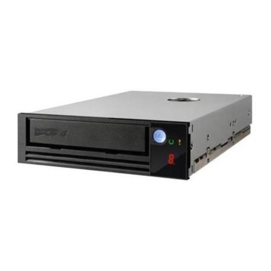
Note Figure 1–3 shows 3.5-inch drive. Positions of the LEDs, switches, etc., apply to the 5.25-inch version also. Figure 1–3 Model TLZ07-AA (3.5-inch Chassis) and TLZ07-BA (5.25-inch Form Factor - Original Version) FrontView WriteProtect TapeUnload TapeUnload TapeUnload TapeUnload TapeUnload TapeUnload... -
Page 15: Revised Version Tlz07-Aa/-Ba Tape Drive
Figure 1–4 Revised Version TLZ07-AA/-BA Tape Drive Write Front View Protect Indicator Tape Tape/ Unload Activity Button Indicator Rear View Jumper Block SCSI Connector Power Connector Bottom View SCSI Address Switch MA00457 TLZ07 Cassette Tape Drive Product Description 1–7... -
Page 16: Checking Your Shipment For Model Tlz07-Da
One 50-pin to 50-pin SCSI signal cable (PN 17-01351-01) for drive to drive connections only. • AC power cable • Five pack of blank cassette tapes (4 mm x 120 m), (PN TLZ07-CB) • One head cleaning cassette tape (PN TLZ04-HA) • SCSI terminator (PN 12-30552-01) •... -
Page 17: Installing The Tabletop Drives/Loaders (Tlz07/Tlz7L)
Installing the Tabletop Drives/Loaders (TLZ07/TLZ7L) 2.1 General This chapter shows you how to install the TLZ07-DA tabletop cassette tape drive or TLZ7L-DA tabletop autoloader on systems with an external SCSI connector. Read the following sections to complete the installation. 2.2 Shut Down, Halt, and Power Off the System... -
Page 18: Selecting The Scsi Address
1. Locate the SCSI address switch at the rear of the tabletop enclosure. 2. Select the SCSI address for the drive: • TLZ07-DA — Press the + or - button until the desired address (0 through 7) appears in the window. See Figure 1–1. •... -
Page 19: Connecting A Scsi Signal Cable - Drive To System
If you do not have this cable, contact your Digital sales representative. You should use a cable supplied by Digital Equipment Corporation. Failure to do so can result in degraded performance of your tabletop drive. -
Page 20: Adding Another Tabletop Drive - Drive To Drive
5. Secure the SCSI cable by snapping the wire cable clamps (on either side of the SCSI connector) into place. 6. Connect the SCSI terminator to the other SCSI connector on the TLZ07-DA drive or TLZ7L-DA autoloader, observing the correct orientation of the cable connector. - Page 21 3. Connect the other end of the power cable to a nearby ac outlet. NOTE Multivendor Customer Services personnel: The power cable disconnects the drive from the main ac power source. Proceed to Chapter 4. Installing the Tabletop Drives/Loaders (TLZ07/TLZ7L) 2–5...
-
Page 23: Installing The Tlz07-Aa/Ba Cassette Tape Drive
Read the following sections to complete the installation. 3.2 Shut Down, Halt, and Power Off the System If you are installing a TLZ07 drive on a running system, have your system manager perform the following steps: 1. Shut down the operating system. -
Page 24: Selecting The Scsi Address For The Tlz07-Aa/Ba Drive
Your system uses a SCSI ID switch to identify, or address, the TLZ07-AA/BA. The SCSI ID is factory set at 0. If you are installing the TLZ07-AA/BA on a system that is already using SCSI ID 0, use any available SCSI ID. (You may have to consult your system manager.) -
Page 25: Scsi Id Switch Settings (0=Off, 1=On)
If the remote SCSI ID jumpers are used, the SCSI ID on the switchpack must be set to the factory default setting of all switches off, ID=0. Table 3–1 SCSI ID Switch Settings (0=Off, 1=On) SCSI ID 0 (default setting) Installing the TLZ07-AA/BA Cassette Tape Drive 3–3... -
Page 26: Scsi Address Switches
Switch S7 allows the drive to report itself as an Archive Python for compatibility with industry standard PC software. When the switch is in the: OFF position, the drive reports itself as a DEC TLZ07 ON position, the drive reports itself as an Archive Python 3–4 Installing the TLZ07-AA/BA Cassette Tape Drive... -
Page 27: Other Optional Switch Settings
Compression enable/disable at power up (S6): Default = compression disabled at power up (S6 = on) • Drive Mode (S7): Switch defaults to off for TLZ07 mode. • Power-on self-test (POST) diagnostic mode enable/disable (S8): Default = POST mode enabled (S8 = on) Figure 3–1 shows the default settings for these switches. -
Page 28: Connecting A Scsi Signal Cable - Drive To System
15-16 Jumper = On (Enabled) MA00458 3.4 Connecting a SCSI Signal Cable — Drive to System If you are connecting a TLZ07 drive directly to your system, you should use a SCSI signal cable supplied as part of your system installation kit. -
Page 29: Connecting The Power Cable And Mounting
Digital service personnel: The power cable disconnects the drive from dc power generated by the main ac power source. CAUTION Always use M3 screws with a maximum thread length of 5 mm to mount the TLZ7L autoloader. Installing the TLZ07-AA/BA Cassette Tape Drive 3–7... -
Page 31: Verifying Tlz07 Cassette Tape Drive Installation
Verifying TLZ07 Cassette Tape Drive Installation 4.1 General To verify successful installation of the TLZ07 drive, execute the power-on self-test (POST). 4.1.1 Execute POST To execute POST: 1. For a tabletop unit, press the power switch to the on or | position (Figure 1–1 and Figure 1–2). - Page 32 After successful execution of POST, have your system manager restart the system and assign a device name to your TLZ07 drive. Optionally, you can run a full system or SCSI bus test. See your system owner’s manual for specific instructions.
-
Page 33: Using The Tlz07 Cassette Tape Drive
(Figure 1–1 through Figure 1–4). It also shows you how to use cassette tapes. 5.2 Power Switch For a tabletop unit, press the power switch to turn the TLZ07 drive on or off. If you are not using the TLZ07 drive for prolonged periods of time, check with your system manager for the correct procedure to shut down your system or power off the drive. -
Page 34: Indicators
In the normal operating state, the Write-Protect LED is used to indicate write-protect status only. • In the normal operating state, the Tape/activity LED is used to indicate drive activity and tape load status. 5–2 Using the TLZ07 Cassette Tape Drive... -
Page 35: Tlz07 Led Status
Flash green, 2 Hz, for both Cleaning tape inserted (good Write-protect status, goes to Flash green during tape) cleaning cycle Cleaning tape inserted Flash amber, 2Hz Flash green, 2 Hz (expired tape) (drive fault) Using the TLZ07 Cassette Tape Drive 5–3... -
Page 36: Using The Cassette Tape
5.7 Using the Cassette Tape Digital Equipment Corporation recommends that you use only DDS certified tapes. The following sections describe how to: • Handle and store tape (Section 5.7.1) • Write-protect tape (Section 5.7.2) • Insert and remove tape (Section 5.7.3) WARNING Always place the tape label in the recessed area on the cassette. -
Page 37: Setting The Write-Protect Tab On The Cassette Tape
Use a pen (NOT A PENCIL) to set the write-protect tab (Figure 5–1) to the desired position. NOTE The tab is not visible when the cassette tape is loaded in the TLZ07 drive. Figure 5–1 TLZ07 Cassette Tape... -
Page 38: Inserting A Cassette Tape Into The Drive
5.7.3 Inserting a Cassette Tape into the Drive Insert the TLZ07 cassette tape into the drive with the cassette’s write-protect tab on the right, facing you. Remove the tape by depressing the tape eject button. CAUTION The drive should never be transported with a tape loaded in the drive. -
Page 39: Preventive Maintenance And Problem Solving
6.1 Cleaning the Heads This section shows you how to perform TLZ07 head cleaning. The heads are the components that physically read and write data to and from the media (in this case, a cassette tape). - Page 40 CAUTION Never attempt to clean the heads in a manner other than described. Doing so will void the product warranty. To clean the heads, use the head cleaning cassette as follows: 1. Apply power to the drive by pressing the power switch on the system external storage expander box, or tabletop drive unit, to the on position.
-
Page 41: Problem Solving
6.2 Problem Solving Table 6–1 describes drive problems and possible solutions. Table 6–1 Problem Solving Symptom Probable Cause Possible Solution Unable to back up or copy data Cassette write-protected. 1. Set write- to cassette tape. protect tab on cassette to write- enabled. -
Page 42: System-Based Diagnostics
6.2.1 System-Based Diagnostics Your system has system-based diagnostics that can be used to test the TLZ07 drive. System-based diagnostics are usually referred to in your system owner’s manual as console-based diagnostics, self-tests, or system exercisers. Refer to your system documentation for information about these diagnostics. -
Page 43: Decservice
6.3.3 DECservice DECservice offers a premium, on-site service for committed response to remedial service requests made during contracted hours of coverage. Remedial maintenance will be performed continuously until the problem is resolved, which makes this service ideal for customers requiring maximum service performance. -
Page 45: Using The Tlz7L Autoloader
5.25-inch full-high form factor with an embedded TLZ07 tape drive and provides all the functionality/features of the TLZ07. The TLZ7L autoloader model is not a field upgrade option for the TLZ07 tape drive; it must be purchased as a single unit. -
Page 46: Model Tlz7L-Aa, Front View
Figure 7–1 Model TLZ7L-AA, Front View Cassette Write Protect Eject DDS-2 Slot Select Dot Matrix Display LJ-03001-TI0 Figure 7–2 Model TLZ7L-AA, Top View Switchpack 1 Switchpack 2 LJ-03002-TI0 7–2 Using the TLZ7L autoloader... -
Page 47: Model Tlz7L-Da, Front View
Figure 7–3 Model TLZ7L-DA, Front View Cassette Write Protect Eject DDS-2 Slot Select LJ-03387-TI0 Using the TLZ7L autoloader 7–3... -
Page 48: Model Tlz7L-Da, Back View
Figure 7–4 Model TLZ7L-DA, Back View ID Select On/Off Switch SCSI Connector LJ-03386-TI0 7–4 Using the TLZ7L autoloader... -
Page 49: Dot Matrix Display
7.3 Dot Matrix Display The indicators (Section 7.2) and the dot matrix display support the same four languages. The dot matrix display shows three types of messages: activity, status, and error. 7.3.1 Activity Messages The dot matrix display has several activity messages: READ when the drive is reading, REWIND when it is rewinding, and so forth. -
Page 50: Loader Error Codes
Table 7–1 Loader Error Codes Error Code Description Possible cause Magazine Initialization Failure Improper cassette insertion Magazine Initialization Failure Improper cassette insertion Magazine Ejection Failure Improper cassette insertion Magazine Positioning Error Improper cassette insertion Magazine Positioning Error Improper cassette insertion Cassette Insertion Failure Contamination or misalignment of cassette insertion rollers... -
Page 51: Status Messages
Table 7–2 Status Messages Message Meaning 0 TAPE This message alternates with the CHK MAG message to indicate that the magazine contains no cartridges. n TAPES After the drawer is closed, this message displays for two seconds to show the number of cartridges in the magazine. CHK MAG The cartridge is not correctly inserted in the magazine, or the magazine contains no cartridges. -
Page 52: Operation
Table 7–2 (Cont.) Status Messages Message Meaning READY A manually inserted cartridge is in the drive and the drive is ready. READY n The cartridge from slot n is in the drive and the drive is ready. REWIND A manually inserted cartridge is rewinding. REWIND n The cartridge from slot n is rewinding. -
Page 53: Manual Operations
stops to prevent accidental overwrite of data unless the continuous cycle switch is set. See Section 7.5.1. Then the magazine may be unloaded. In Random Access mode, the loader responds to all of the SCSI Random Access commands. 7.4.2 Manual Operations Manual operations are performed from the front of the autoloader. -
Page 54: Switch Settings And Jumpers
7.5 Switch Settings and Jumpers 7.5.1 Switchpack 1 Switchpack 1, or SW1 (Table 7–3), is located at the top of the drive. It is accessible through a cutout in the top cover of the drive. The drawer must be in the open position when you access this switchpack. The default is for all switches off. -
Page 55: Switchpack 2
SW1-3 You select the Continuous Cycle mode by setting switch SW1-3. When you set this switch to on, the autoloader loads the first cassette after unloading the last cassette in Sequential mode. This switch defaults to off. CAUTION Continuous Cycle mode may overwrite existing data. SW1-4 You select the intensity of the dot matrix display by setting switch SW1-4. -
Page 56: Scsi Id Select Switch (-Da Version Only)
7.5.3 SCSI ID Select Switch (-DA Version Only) The SCSI ID Select Switch is located in the upper right corner on the rear of the tabletop loader enclosure (Figure 7–4). Table 7–6 indicates the proper switch positions for each possible SCSI ID. Table 7–6 SCSI ID Select Switch SCSI ID 0 (Default) -
Page 57: Other Switch Settings
Compression enable/disable at power up (S6): Default = compression disabled at power up (S6 = on) • Drive Mode (S7): Switch defaults to off for TLZ07 mode. • Power-on self-test (POST) diagnostic mode enable/disable (S8): Default = POST mode enabled (S8 = on) Figure 7–5 shows the default settings for these switches. -
Page 58: Termination Jumper/Terminators
Switch S7 allows the drive to report itself as an Archive Python for compatibility with industry standard PC software. When the switch is in the: OFF position, the drive reports itself as a DEC TLZ07 ON position, the drive reports itself as an Archive Python 7.5.6 Termination Jumper/Terminators The last unit in a daisy chain of SCSI devices must have termination installed. -
Page 59: Routine Maintenance
SCSI terminator power is provided by the loader. 7.6 Routine Maintenance 7.6.1 Cleaning the Rollers Digital Equipment Corporation recommends that you clean the rollers about once every 6 months or after 10,000 load/unload cycles. Follow these steps: 1. Open the drawer and remove the magazine. -
Page 61: A Cassette Tape Drive Specifications
Cassette Tape Drive Specifications The following tables list the TLZ07 and TLZ7L cassette tape drive specifications. Table A–1 TLZ07 Cassette Tape Drive Specifications Characteristic Specification(s) Mode of operation Streaming, and start/stop Drive interface Small computer system interconnect (SCSI-2) Dimensions See Table A–2... -
Page 62: Tlz07 Cassette Tape Drive Dimensions
Table A–1 (Cont.) TLZ07 Cassette Tape Drive Specifications Characteristic Specification(s) Internal SCSI cable length 130 mm (TLZ07-DA) Passes per cassette tape 2000 Power consumption (typical) Tabletop 12 W Drive Power requirements Tabletop (TLZ07-DA) 100 to 240 V ac, 0.3 A Drive (TLZ07-AA/BA) +5 V dc, 0.89 A... -
Page 63: Tlz07-Da Noise Declaration
Table A–3 TLZ07-DA Noise Declaration Acoustics - declared values per ISO 9296 and ISO 7779: LwAd LpAm (bystander positions) Idle 4,7 B 34 dBA Operating 4,8 B 35 dBA Schallemissionswerte - Werteangaben nach ISO 9296 und ISO 7779/DIN EN27779: LwAd... -
Page 64: Tlz7L Cassette Tape Drive Specifications
Table A–4 TLZ7L Cassette Tape Drive Specifications Characteristic Specification(s) Mode of operation Streaming and Start/stop Drive interface SCSI-2 Dimensions See Table A–5 Media See Table A–1 Bit density See Table A–1 Transfer rate See Table A–1 Recording format See Table A–1 Cassette capacity (typical) See Table A–1 Magazine capacity, 4-cartridge (typical) -
Page 65: Tlz7L Cassette Tape Drive Dimensions
Table A–5 TLZ7L Cassette Tape Drive Dimensions Dimensions TLZ7L-AA TLZ7L-DA Height 82 mm (3.2 in) 147 mm (5.77 in) Width 146 mm (5.7 in) 23.5 mm (9.25 in) Length 205 mm (8 in) 33.3 mm (13.1 in) Weight 2.7 kg (6 lb) 5 kg (11 lb) Table A–6 TLZ7L-DA Noise Declaration Acoustics - declared values per ISO 9296 and ISO 7779:... -
Page 67: B Enabling/Disabling Data Compression Under Osf And
Enabling/Disabling Data Compression Under OSF and OpenVMS B.1 OSF TLZ07 Compression and Noncompression Modes The default mode for the TLZ07 tape drive is noncompression mode. To use the TLZ07 tape drive in compression mode, specify the device as: /dev/rmt?h or /dev/rmt?m... -
Page 68: Openvms Tlz07 Compression And Noncompression Modes
B.3 OpenVMS TLZ07 Compression and Noncompression Modes The default mode for the TLZ07 tape drive is noncompression mode. To use the TLZ07 tape drive in compression mode, specify: MEDIA_FORMAT=COMPACT software switch To use the TLZ07 tape drive in noncompression mode, specify:... -
Page 69: Index
5–5 TLZ7L autoloader, 7–1 Checking your shipment, 1–8 Inserting a cassette tape into the drive, 5–6 Checking your Shipment for Model for Installing the TLZ07-AA/BA cassette tape TLZ07/7L, 1–8 drive, 3–1 Design features, 1–2 Media Recognition System (MRS), 1–3... - Page 70 TLZ7L cassette tape loader Switch settings, 7–13 location of buttons, switches, connectors, System support, 1–2 2–2 Tape indicator, 5–2 Unload button, 5–1 TLZ07 cassette tape drive indicators, 5–5 installation verification, 4–1 Write-protect LED, 5–1 location of buttons, switches connectors, Write-protect tab, 5–5 3–2...
Need help?
Do you have a question about the TLZ07 and is the answer not in the manual?
Questions and answers