
Related Manuals for Digital Equipment TLZ09


Summary of Contents for Digital Equipment TLZ09
- Page 1 TLZ09 Cassette Tape Drive Owner’s Manual Order Number: EK-TLZ09-OM. C01 Digital Equipment Corporation Maynard, Massachusetts...
- Page 2 October 1996 Digital Equipment Corporation makes no representations that the use of its products in the manner described in this publication will not infringe on existing or future patent rights, nor do the descriptions contained in this publication imply the granting of licenses to make, use, or sell equipment or software in accordance with the description.
- Page 3 Für Bundesrepublik Deutschland For Federal Republic of Germany Pour la République féderal d’Allemagne BESCHEINIGUNG DES HERSTELLERS/IMPORTEURS Dieses Gerät ist in Übereinstimmung mit den Bestimmungen der BMPT Vfg.243/1991 und Vfg.46/1992 in Verbindung mit EN55022:1987 (DIN VDE 0878-3:11.89), oder Vfg.1046/1984 mit Vfg. 483/1986, funkentstört. Es trägt als Nachweis der EMV-Konformität entweder eine Konformitätskennzeichnung oder das VDE-Funkschutzzeichen.
-
Page 5: Table Of Contents
1–3 TLZ09/9L Models ........ -
Page 6: General
3–6 4 Verifying TLZ09 Cassette Tape Drive Installation General .......... -
Page 7: General
Digital UNIX DUMP Utility ......B–1 OpenVMS TLZ09 Compression and Noncompression Modes ..B–2... - Page 8 Drive Switch Settings ......3–2 3–5 5–1 TLZ09 Cassette Tape ....... 5–6 viii...
- Page 9 SCSI ID Jumper Settings (0=Removed, 1=Installed) ..3–3 TLZ09 LED Status ....... . . 5–1 5–2...
-
Page 11: Tlz09/9L Cassette Tape Device Product Description
3. The compression measurements are typical for a 2-to-1 data compression ratio, but the actual ratio is dependent on the data. The maximum time to back up (read or write) on a TLZ09/9L cassette tape in a continual (streaming) mode is system dependent. The efficient use of streaming mode is determined by your operating system. -
Page 12: System Support
1.1.1 System Support As of this printing, the TLZ09/9L device is supported by a variety of Digital systems. Consult your Digital Sales Support representative for a list of supported systems. Your particular system must have an available standard SCSI (Small Computer System Interconnect) port in order to connect the TLZ09 or TLZ9L. -
Page 13: What Is The Media Recognition System (Mrs)
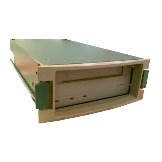
Model TLZ09-VA — a TLZ09-AA mounted in a 3 1/2-inch StorageWorks SBB. • Model TLZ09-AX — a field spare unit that is configurable to an -AA, -AB, -BA, or -BB model. Includes bezel and rail installation procedures. NOTE All the models have a drive buffer size of 1 MB of memory. -
Page 14: Model Tlz09-Da/Db (Tabletop)
Figure 1–1 Model TLZ09-DA/DB (Tabletop) On/Off Power On Busy Tape Status Eject/Unload Switch Button SCSI CONNECTOR AC IN SCSI ID SCSI Connectors AC Power SCSI ID Recepticle Indicator/Switch MLO-011795 1–4 TLZ09/9L Cassette Tape Device Product Description... -
Page 15: Model Tlz09-Aa/Ab (3.5-Inch Chassis)
Figure 1–2 Model TLZ09-AA/AB (3.5-inch Chassis) Busy Tape Status Eject/Unload Button Configuration SCSI DC Power Jumper Block Connector Connector MLO-011796 TLZ09/9L Cassette Tape Device Product Description 1–5... -
Page 16: Model Tlz09-Ba/Bb (5.25-Inch Chassis)
Figure 1–3 Model TLZ09-BA/BB (5.25-Inch Chassis) Busy Tape Status Eject/Unload Button 5.25" Side Configuration SCSI DC Power 5.25" Side Mounting Rails Jumper Block Connector Connector Mounting Rails MLO-011797 1–6 TLZ09/9L Cassette Tape Device Product Description... -
Page 17: Tlz09 Chassis-Underside With Switch Pack
Figure 1–4 TLZ09 Chassis–Underside with Switch Pack Drive Mode TLZ09 (Off) MRS Detect Disabled (Off) Self Test Enabled (Off) Reserved (Off) 2 3 4 MLO-011799 TLZ09/9L Cassette Tape Device Product Description 1–7... -
Page 18: Checking Your Shipment For Model Tlz09-Da/Db
One 50-pin to 50-pin (low density to high density connector) SCSI signal cable for drive to system connections. PN 17-04356-01 is frost white and is packaged with the TLZ09-DB, while PN 17-03742-09 is gray and is packaged with the TLZ09-DA. In the future, black cables may be substituted for both of these variations. -
Page 19: Ordering Additional Cassettes
Five blank cassette tapes (4 mm x 60 m) (PN TLZ04-CB) • Five blank cassette tapes (4 mm x 90m) (PN TLZ06-CB) • Five blank cassette tapes (4 mm x 120m) (PN TLZ07-CB) • One head cleaning cassette (PN TLZ04-HA) TLZ09/9L Cassette Tape Device Product Description 1–9... -
Page 21: Installing The Tabletop Drive Or Autoloader (Tlz09-Da/Db Or Tlz9L-Da/Db)
2.2 Shut Down, Halt, and Power Off the System If you are installing a TLZ09-DA/DB tabletop cassette tape drive or a TLZ9L- DA/DB tabletop cassette tape autoloader on a running system, have your system manager perform the following steps: 1. -
Page 22: Selecting The Scsi Address
2.3 Selecting the SCSI Address To familiarize yourself with the TLZ09 drive and TLZ9L autoloader: 1. Refer to Figure 1–1 for the location of the buttons, switches, and connectors on the tabletop drive and to Figure 7–2 for the location of the buttons, switches, and connectors on the tabletop autoloader. -
Page 23: Connecting A Scsi Signal Cable - Device To System
If you do not have this cable, contact your Digital sales representative. You should use a cable supplied by Digital Equipment Corporation. Failure to do so can result in degraded performance of your tabletop device. -
Page 24: Adding Another Tabletop Device - Device To Device
5. Secure the SCSI cable by snapping the wire cable clamps (on either side of the SCSI connector) into place. 6. Connect the SCSI terminator to the other SCSI connector on the TLZ09- DA/DB drive or TLZ9L-DA/DB autoloader, observing the correct orientation of the cable connector. -
Page 25: Connecting The Power Cable
The tabletop devices have an autoranging power supply. Refer to Table A–1 or Table A–4 for voltage specifications. To connect the power cable, proceed as follows: 1. Be sure that the TLZ09-DA/DB drive or TLZ9L-DA/DB autoloader power switch is off (0). 2. Connect the power cable to the TLZ09-DA/DB drive or TLZ9L-DA/DB autoloader power connector. -
Page 27: Installing The Tlz09-Aa/Ab, -Ba/Bb Cassette Tape Drive
Read the following sections to complete the installation. 3.2 Shut Down, Halt, and Power Off the System If you are installing a TLZ09 drive on a running system, have your system manager perform the following steps: 1. Shut down the operating system. -
Page 28: Selecting The Jumper And Switch Configuration For The Tlz09-Aa/Ab, -Ba/Bb Drive
Your system uses a SCSI ID jumper block to identify, or address, the TLZ09. The SCSI ID is factory set at 0. If you are installing the TLZ09 on a system that is already using SCSI ID 0, use any available SCSI ID. (You may have to consult your system manager.) -
Page 29: Configuration Jumper Block
11 13 10 12 14 Terminator Power Enabled Termination Disabled Reserved SCSI Parity Enabled MLO-011798 NOTE The drive must be powered down and then powered up for new jumper settings to take effect. Installing the TLZ09-AA/AB, -BA/BB Cassette Tape Drive 3–3... -
Page 30: Other Optional Jumper Settings
3.3.3 Drive Switch Settings The drive switch (see Figure 3–2) allows you to configure the following options: • Drive Mode (S1): Switch defaults to off for TLZ09 mode (on indicates generic mode) • Media Recognition System Detect Enable/Disable (S2): Switch defaults to off for no MRS detection. -
Page 31: Drive Switch Settings
Figure 3–2 Drive Switch Settings Drive Mode TLZ09 (Off) MRS Detect Disabled (Off) Self Test Enabled (Off) Reserved (Off) 2 3 4 MLO-011799 Installing the TLZ09-AA/AB, -BA/BB Cassette Tape Drive 3–5... -
Page 32: Connecting A Scsi Signal Cable - Drive To System
3.4 Connecting a SCSI Signal Cable — Drive to System If you are connecting a TLZ09 drive directly to your system, you should use a SCSI signal cable supplied as part of your system installation kit. If you do not have this cable, contact your Digital sales representative. You should use a cable supplied by Digital. -
Page 33: Verifying Tlz09 Cassette Tape Drive Installation
Verifying TLZ09 Cassette Tape Drive Installation 4.1 General To verify successful installation of the TLZ09 drive, execute the power-on self-test (POST). 4.1.1 Execute POST To execute POST: 1. For a tabletop unit, press the power switch to the on or | position (Figure 1–1). - Page 34 After successful execution of POST, have your system manager restart the system and assign a device name to your TLZ09 drive if necessary. Optionally, you can run a full system or SCSI bus test. See your system owner’s manual for specific instructions.
-
Page 35: Using The Tlz09 Cassette Tape Drive
(Figures 1–1 through 1–3). It also shows you how to use cassette tapes. 5.2 Power Switch For a tabletop unit, press the power switch to turn the TLZ09 drive on or off. If you are not using the TLZ09 drive for prolonged periods of time, check with your system manager for the correct procedure to shut down your system or power off the drive. -
Page 36: Status Led
(on) or unloaded (off) Reset sequence Flashes on for 1 Off, then indicates Off, then indicates second tape load status. write-protect status. (continued on next page) 5–2 Using the TLZ09 Cassette Tape Drive... - Page 37 One long flash every then indicates four seconds if drive activity. On during was requesting a subsequent unload cleaning cycle. On sequence. during subsequent unload sequence. (continued on next page) Using the TLZ09 Cassette Tape Drive 5–3...
- Page 38 Table 5–1 (Cont.) TLZ09 LED Status Condition Busy LED Tape LED Status LED Cleaning Flashes twice per tape inserted second. Continues (expired tape) until eject button is pushed, at which time a normal unload cycle is initiated. 5–4 Using the TLZ09 Cassette Tape Drive...
-
Page 39: Using The Cassette Tape
5.5 Using the Cassette Tape Digital Equipment Corporation recommends that you use only DDS certified tapes. The following sections describe how to: • Handle and store tape (Section 5.5.1) • Write-protect tape (Section 5.5.2) • Insert and remove tape (Section 5.5.3) WARNING Always place the tape label in the recessed area on the cassette. -
Page 40: Setting The Write-Protect Tab On The Cassette Tape
Use a pen (NOT A PENCIL) to set the write-protect tab (Figure 5–1) to the desired position. NOTE The tab is not visible when the cassette tape is loaded in the TLZ09 drive. Figure 5–1 TLZ09 Cassette Tape... -
Page 41: Inserting A Cassette Tape Into The Drive
5.5.3 Inserting a Cassette Tape into the Drive Insert the TLZ09 cassette tape into the drive with the cassette’s write-protect tab on the right, facing you. Remove the tape by depressing the tape eject button. CAUTION The drive should never be transported with a tape loaded in the drive. -
Page 43: Preventive Maintenance And Problem Solving
6.1 Cleaning the Heads This section shows you how to perform TLZ09 head cleaning. The heads are the components that physically read and write data to and from the media (in this case, a cassette tape). - Page 44 CAUTION Never attempt to clean the heads in a manner other than described. Doing so will void the product warranty. To clean the heads, use the head cleaning cassette as follows: 1. Apply power to the drive by pressing the power switch to the on position on the system external storage expander box, the tabletop drive unit, or the system enclosure for embedded drives.
-
Page 45: Problem Solving
6.2 Problem Solving Table 6–1 describes drive problems and possible solutions. See also Table 5–1. Table 6–1 Problem Solving Symptom Probable Cause Possible Solution Unable to back up or copy Cassette write- 1. Set write-protect tab on data to cassette tape. protected. -
Page 46: System-Based Diagnostics
6.2.1 System-Based Diagnostics Your system has system-based diagnostics that can be used to test the TLZ09 drive. System-based diagnostics are usually referred to in your system owner’s manual as console-based diagnostics, self-tests, or system exercisers. Refer to your system documentation for information about these diagnostics. -
Page 47: Basic Service
6.3.2 BASIC Service BASIC Service offers full coverage from 8 a.m. to 5 p.m., Monday through Friday. Options are available to extend your coverage to 12-, 16- or 24-hour periods, and to include Saturdays, Sundays, and holidays. Under the BASIC service plan all parts, materials and labor are covered in full. -
Page 49: Using The Tlz9L Cassette Tape Autoloader
TLZ09 cassette tape drive, and provides all the functionality and features of the TLZ09. The TLZ9L autoloader is NOT a field upgrade option for the TLZ09 tape drive. It must be purchased as a single unit. With the 8-cartridge magazine (PN TLZ9L-08), the TLZ9L autoloader provides up to 64 gigabytes of storage. -
Page 50: Led Indicators
7.2 LED Indicators The basic TLZ9L autoloader has two LEDs labeled BUSY and TAPE. The tabletop TLZ9L autoloader has an additional LED indicator labeled POWER which illuminates when power is applied. The status of the BUSY and TAPE LEDs during various conditions is described in Table 7–1. -
Page 51: Model Tlz9L-Aa (Front And Bottom View)
Figure 7–1 Model TLZ9L-AA (Front and Bottom View) EJECT SELECT BUSY TAPE 5 6 7 C Busy Tape Cartridge Eject Button Select Button Continuous-Cycle Mode Disabled (ON) Reserved (ON) MLO-013654 Using the TLZ9L Cassette Tape Autoloader 7–3... -
Page 52: Model Tlz9L-Da/Db (Front And Rear View)
Figure 7–2 Model TLZ9L-DA/DB (Front and Rear View) Power On LED Magazine Door POWER EJECT SELECT BUSY TAPE 5 6 7 C Power Busy Tape Cartridge Eject Button Switch Select Button SCSI CONNECTOR SCSI ID AC IN Ground Cooling SCSI ID AC Receptacle SCSI Connectors Connection... -
Page 53: Lcd Panel
7.3 LCD Panel The liquid crystal display (LCD) panel on the TLZ9L autoloader contains five separate indicators that provide status as well as error information to the user (see Figure 7–3). Figure 7–3 TLZ9L LCD Panel Error Indicator Warning Indicator 7-Segment Numeric Indicator Write-Protect... -
Page 54: Warning Indicator
7.3.1 Warning Indicator The warning indicator is illuminated upon occurrence of a warning condition. When this indicator is lit in combination with a number in the 7-segment display, a particular warning or caution can be indicated. Table 7–2 lists the warning and numeric combinations with a description of what they indicate when lit. -
Page 55: Write Protect Indicator
7.3.2 Write Protect Indicator The Write-Protect indicator (WP) is illuminated when a write-protected data cartridge is inserted into the drive. Write-protect can be set by the write-protect tab on either the magazine (write-protects all cartridges in the magazine) or the individual tape cartridge (write-protects the individual data cartridge). -
Page 56: Error Indicator
7.3.3 Error Indicator The error indicator is illuminated when certain errors occur. When this indicator is lit in combination with a number in the 7-segment display, a particular error can be indicated. Table 7–3 lists the error and numeric combinations with a description of what they indicate when lit. Table 7–3 Error Indications Indicator and Number Error Message... -
Page 57: Tlz9L Operation
7.4 TLZ9L Operation The TLZ9L cassette tape autoloader can operate in two ways; automatically or manually. It can also be operated in two modes; sequential or random access. CAUTION Never transport the autoloader with a magazine installed. Damage to the tapes, autoloader, or magazine may result due to movement of the magazine. -
Page 58: Magazine Operations
drive, the autoloader will unload that cartridge, place it back in the magazine, and then load the selected cartridge. 7.4.3 Magazine Operations The TLZ9L cassette tape autoloader supports three basic magazine configurations. These configurations are 8, 7, and single-cartridge modes. Any other number of cartridges is not supported and will cause the magazine to eject. -
Page 59: Seven Cartridge Mode
7.4.3.2 Seven Cartridge Mode In seven cartridge mode the C slot is left vacant as shown in Figure 7–6. When the magazine is inserted into the autoloader, the C slot is not available for use by the autoloader. Any attempt to access the C slot will generate an error. Figure 7–6 Seven Cartridge Mode C or 8 MLO-013659... -
Page 60: Single Cartridge Mode
7.4.3.3 Single Cartridge Mode In single cartridge mode, either a data cartridge or a cleaning cartridge is inserted into the C slot position of the magazine as shown in Figure 7–7. When the magazine is inserted into the autoloader, the cartridge is automatically loaded into the drive. -
Page 61: Loading Cartridges Into The Magazine
7.4.3.4 Loading Cartridges Into the Magazine When loading data cartridges into the magazine, the bottom shelf of the magazine should be loaded first. Ensure that the cartridges are oriented correctly as shown in Figure 7–8. Load cartridge 3 in the bottom shelf first, followed by cartridge 2 and then cartridge 1 in that order. -
Page 62: Loading The Magazine Into The Tlz9L
7.4.3.5 Loading the Magazine Into the TLZ9L To load a magazine into the TLZ9L cassette tape autoloader, first apply power to the autoloader by powering on the system for an embedded autoloader, or by pressing the power switch on the tabletop autoloader. The BUSY and TAPE LED indicators blink as a self-test is performed. -
Page 63: Ejecting The Magazine
7.4.3.6 Ejecting the Magazine Under normal conditions, the magazine can be ejected by simply pressing the Eject button on the front panel. Any cartridge that may be in the drive at the time the Eject button is pressed will be rewound and unloaded back into the magazine. -
Page 64: Unloading Cartridges From The Magazine
7.4.3.7 Unloading Cartridges From the Magazine When unloading cartridges from a magazine, it is recommended that the magazine be held over a table or bench so that the cartridges will fall gently to the table top and not fall on the floor where they could be damaged. Perform the unloading process by pressing down on the magazine slide latch with the thumb of your left hand and then placing the finger of your right hand in the hole at the rear of the magazine and pushing the cartridges toward the... -
Page 65: Switch Settings
7.5 Switch Settings The following sections describe the switchpack settings on the TLZ9L autoloader and the SCSI ID select switch on the TLZ9L-DA/DB autoloader. It should be noted that all of the drive switches and jumpers still function as documented in Chapter 3 for the drive mounted internal to the autoloader. For example, to enable MRS detection on the autoloader, place drive switch S2 to the ON position (see Section 3.3.3 and Figure 3–2). -
Page 66: Cleaning Requirements
7.6 Cleaning Requirements A cleaning tape preventive maintenance program is required. Head cleaning shall be the only preventive maintenance required and shall be accomplished with a tape cleaning cartridge. The Digital part number for the cleaning cartridge is TLZ04-HA. A cleaning cycle should be performed at the following times: •... - Page 67 Sequential Mode: • Place the cleaning cartridge into any magazine slot along with data cartridges appropriate for the mode of operation (i.e. 7 cartridge mode, or 8 cartridge mode) • Insert the magazine into the autoloader • Use the select button to select the slot with the cleaning cartridge •...
-
Page 69: Tlz09 Cassette Tape Drive Specifications
Cassette Tape Drive and Autoloader Specifications The following tables list the TLZ09 cassette tape drive specifications. Table A–1 TLZ09 Cassette Tape Drive Specifications Characteristic Specification(s) Mode of operation Streaming, and start/stop Drive interface Small Computer System Interconnect (SCSI-2) Dimensions See Table A–2... -
Page 70: Tlz09 Cassette Tape Drive Dimensions
Table A–1 (Cont.) TLZ09 Cassette Tape Drive Specifications Characteristic Specification(s) Operating altitude 0 to 4.6 km (0 to 15,000 ft) Nonoperating altitude 0 to 4.9 km (0 to 16,000 ft) Internal SCSI cable length 145 mm (TLZ09-DA/DB) Passes per cassette tape... -
Page 71: Tlz09-Da Noise Declaration
Table A–3 TLZ09-DA Noise Declaration Acoustics - declared values per ISO 9296 and ISO 7779: LwAd LpAm (bystander positions) Idle 4.8 B 39 dBA Operating 4.9 B 40 dBA Schallemissionswerte - Werteangaben nach ISO 9296 und ISO 7779/DIN EN27779: LwAd... -
Page 72: Tlz9L Cassette Tape Autoloader Specifications
The following tables list the TLZ9L cassette tape autoloader specifications. Table A–4 TLZ9L Cassette Tape Autoloader Specifications Characteristic Specification(s) Mode of operation Streaming, and start/stop Drive interface Small Computer System Interconnect (SCSI-2) Dimensions See Table A–5 Media (4 mm x 60 m) TLZ04-CA cassette tape Media (4 mm x 90 m) TLZ06-CA cassette tape... -
Page 73: Tlz9L Cassette Tape Autoloader Dimensions
Table A–4 (Cont.) TLZ9L Cassette Tape Autoloader Specifications Characteristic Specification(s) Power consumption (typical, write mode) Tabletop 30 W Embedded 8.4 W Power requirements (typical) Tabletop (TLZ9L-DA/DB) 100 V ac, 0.3 A 240 V ac, 0.14 A Embedded (TLZ9L-AA) +5 V dc, 1.2 A Embedded (TLZ9L-AA) +12 V dc, 0.2 A Table A–5 TLZ9L Cassette Tape Autoloader Dimensions... -
Page 74: Tlz9L-Da/Db Noise Declaration
Table A–6 TLZ9L-DA/DB Noise Declaration Acoustics - declared values per ISO 9296 and ISO 7779: LwAd LpAm (bystander positions) Idle 4.7 B 33 dBA Operating 4.8 B 34 dBA Schallemissionswerte - Werteangaben nach ISO 9296 und ISO 7779/DIN EN27779: LwAd LpAm (Zuschauerpositionen) Leerlauf 4,7 B... -
Page 75: B Enabling/Disabling Data Compression Under Digital Unix And Openvms
B.1 Digital UNIX TLZ09 Compression and Noncompression Modes The default mode for the TLZ09 tape drive is for compression mode. For software control of compression, use the following commands. To use the TLZ09 tape drive in compression mode, specify the device as:... -
Page 76: Openvms Tlz09 Compression And Noncompression Modes
B.3 OpenVMS TLZ09 Compression and Noncompression Modes The default mode for the TLZ09 tape drive is for compression mode. For software control of compression, use the following commands. To use the TLZ09 tape drive in compression mode, specify: MEDIA_FORMAT=COMPACT software switch... -
Page 77: C Product Notes For Non-Digital Platforms
Windows NT This section provides information for the system administrator who should read this material before installing and using the TLZ09 DAT tape drive or TLZ9L autoloader with a host system operating under the Novell NetWare or Microsoft Windows NT operating systems. - Page 78 This product is supported only under Windows NT version 3.51 by adding the "4 millimeter Sony drive" tape device option. Follow the Windows NT "Add/Remove Tape Devices" procedure to add this support. This product is supported only under Windows NT version 4.0 by adding the "4 millimeter DAT drive"...
-
Page 79: Product Notes For Sun
C.2 Product Notes for Sun This section describes how to include the TLZ09 DAT tape drive or TLZ9L autoloader in a Sun SPARC system running Solaris 2.3 (or later) or SunOS 4.1.x. The information covers configuration of the host system to communicate with the tape drive. -
Page 80: Modifications Required For Sunos 4.1
For additional information on this requirement, read the man pages for "st". C.2.2.2 System Modification Perform the following steps to modify the system for communication with the TLZ9L autoloader (see notes at the end of this sub-section for TLZ09 differences): 1. From the command line, type: cd /sys/scsi/targets 2. -
Page 81: Rebuilding Of Kernel
The tenth parameter ( ) is the speed code (not used). 0, 0, 0, 0 For the TLZ09 DAT tape drive, perform the same steps as for the TLZ9L, with the following exceptions: In step 2, instead of "DEC 8GB 4mm Helical Scan", 12, "DEC^^^^^TLZ9", Substitute: "DEC 8GB 4mm Helical Scan", 13, "DEC^^^^^TLZ09",... -
Page 82: Installation Of Tape Drive
C.2.2.4 Installation of Tape Drive Install the tape drive into the storage subsystem and power on the workstation. We recommend that the tape drive’s SCSI device address be set to ID 4 or to ID 5. NOTE If your SCSI host adapter is supported by the "probe-scsi"... -
Page 83: Verification
Note that depending on the size of the file, a different number of blocks may be reported. C.2.2.7 Verification Verify that the "passwd" file was written to tape using the following command: tar tvf /dev/rst0 The system responds with something similar to the following: rw-r--r-- 0/10 535 Mar 23 16:31 1994 /etc/passwd The installation and verification procedure is now complete. -
Page 84: System Modification
C.2.3.2 System Modification Perform the following steps to modify the system to communicate with the autoloader (see notes at the end of this sub-section for TLZ09 differences): 1. From the command line, type: cd /kernel/drv 2. Edit the "st.conf" file by adding the following before the first occurrence of "name=":... -
Page 85: System Shutdown
The last parameter in the data string is the default density of 3 for the 120-m DDS2 tape in the compressed mode. For the TLZ09 DAT tape drive, perform the same steps as for the TLZ9L with the following exceptions: In step 2, instead of "tape-config-list = "DEC^^^^^TLZ9",... -
Page 86: Rebooting Of System
C.2.3.5 Rebooting of System Reboot the system using the following command at the boot prompt: >boot -rv Note that the switch "r" forces the kernel to be re-configured, and switch "v" enables a display of the system configuration at boot time. The system compiles the kernel and creates special files in /dev so that it can communicate with the tape drive. -
Page 87: Test
• rst20 and nrst20 correspond to the 0xfe density mode (120-m DDS2 tape, compressed format) • rst28 and nrst28 correspond to the 0xfe density mode (120-m DDS2 tape, compressed format) C.2.3.6 Test To test the tape drive, back up the "passwd" file to tape using the "tar" command, as follows: tar cvf /dev/rst4 /etc/passwd... -
Page 88: Product Notes For Ibm Rs/6000
C.3 Product Notes for IBM RS/6000 This section provides information for the system administrator. It should be read before installing and using the TLZ09 DAT tape drive or TLZ9L autoloader with a host system with the AIX 3.2.5 (or later) operating system. -
Page 89: Installing The Tape Drive Using Command-Line Interface
C.3.1.2 Installing the Tape Drive Using Command-Line Interface 1. From the command line, type: # cfgmgr 2. To determine which rmt has been added, type: # lsdev -Cc tape Example: # lsdev -Cc tape Name Status Location Description rmt0 Available 00-03-00-50 Other SCSI Tape Drive 3. -
Page 90: Using The Tape Drive To Install Aix
The files that are created are: Tape Drive Special File Characteristics Special File Name Rewind-on-Close Retention-on-Open Bytes-per-Inch /dev/rmt* Density Setting # 1 /dev/rmt*.1 Density Setting # 1 /dev/rmt*.2 Density Setting # 1 /dev/rmt*.3 Density Setting # 1 /dev/rmt*.4 Density Setting # 2 /dev/rmt*.5 Density Setting # 2 /dev/rmt*.6... -
Page 91: Product Notes For Hewlett-Packard
C.4 Product Notes for Hewlett-Packard This section describes how to include the TLZ09 DAT tape drive or TLZ9L autoloader in an HP 9000 Series 700 system running HP-UX 9.05, 10.01, or 10.10 and Series 800 system running HP-UX 10.10. The information covers configuration of the host system to communicate with the tape drive. -
Page 92: Installation Procedure
SCSI tape drive (HP-UX 9.05), or as a DEC TLZ9 or DEC TLZ09 (HP-UX 10.x) with the appropriate hardware path. Highlight that selection and then pull down the Actions menu and select the Add function. -
Page 93: Hp-Ux
C.4.2.5 HP-UX 9.05 The following naming convention is used for the DDS-format tape drive, as shown in the examples listed below: /dev/rmt/c#d#[hlmc][n][b] Where: specifies the controller designation, which may contain either two or three characters, specifies the following: where # is sc[f], in accordance with the following: is the system bus module: 2 = core I/O (the default) 4 = EISA SCSI... -
Page 94: Hp-Ux
Examples: For a tape drive installed in slot location 4 of the Digital StorageWorks SWXSE-02 expansion enclosure connected to the main (core) SCSI bus, the following device files would be produced in the directory /dev/rmt: c201d4c c201d4l c201d4cb c201d4lb c201d4cn c201d4ln c201d4cnb c201d4lnb... -
Page 95: Testing The Tape Drive
For systems which do not support long filenames, the following device naming convention is used: #mnb Where: specifies an arbitrary number to distinguish this tape drive from others. specifies no rewind on close specifies Berkeley behavior To list the device files associated with each device, issue the command: ioscan -f -n|more C.4.3 Testing the Tape Drive To test the tape drive, back up the "passwd"... -
Page 96: Dump Parameters For The Tape Drive
C.4.3.2 Dump Parameters for the Tape Drive The parameters that should be used when running the dump utility with the tape drive are: density = 61000 (for DDS1 or DDS2 tapes) size = one of the following, as appropriate: 6656 (for 60 meter tapes) 10240 (for 90 meter tapes) 20480 (for 120 meter tapes) blocking factor = 128... -
Page 97: Index
Head cleaning cassette, 6–2 Cartridge number indicators, 7–8 Cassette magazine Inserting a cassette tape into the drive, 5–7 setting the write-protect tab, 7–7 Installing the TLZ09-AA/BA cassette tape Cassette tape drive, 3–1 handling of, 5–5 setting the write-protect tab, 5–6 Checking your shipment, 1–8... - Page 98 7–7 Tape LED, 5–2 TLZ07 cassette tape drive Unload button, 5–1 location of buttons, switches connectors, 3–2 TLZ09 cassette tape drive busy LED, 5–2 Warning indicator, 7–6 indicators, 5–6 Write-protect indicator, 7–7 installation verification, 4–1 Write-protect tab, 5–6, 7–7 location of buttons, switches, connectors, 2–2...
Need help?
Do you have a question about the TLZ09 and is the answer not in the manual?
Questions and answers