Table of Contents
Advertisement
Quick Links
Instructions - Parts List
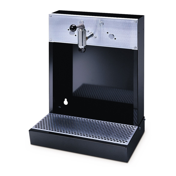
Dispenser Bar
Model 220107, Series A
900 psi (6.2 MPa, 62 bar) Maximum Fluid Working Pressure
Model 220107, Series A, with Meter Kit 239706
500 psi (3.4 MPa, 34 bar) Maximum Fluid Working Pressure
Important Safety Instructions
Read all warnings and instructions in this manual.
Save these instructions.
Table of Contents
. . . . . . . . . . . . . . . . . . . . . . . . . . . . . . .
Dispenser Bar Parts
. . . . . . . . . . . . . . . . . . . . . .
Dispensing Valve Parts
. . . . . . . . . . . . . . . . . . . .
Accessories
. . . . . . . . . . . . . . . . . . . . . . . . . . . . .
Dimensions
. . . . . . . . . . . . . . . . . . . . . . . . . . . . . .
. . . . . . . . . . . . . . . . . . . . . . . . . . .
. . . . . . . . . . . . . . . . . . . . . . . . . . . . . . . .
. . . . . . . . . . . . . . . . . . . . .
GRACO INC. P.O. BOX 1441 MINNEAPOLIS, MN 55440-1441
Copyright 2002, Graco Inc. is registered to I.S. EN ISO 9001
2
3
. . . . . . . . . . . . . . . . .
4
5
6
7
7
8
8
307742L
ENG
04203
Without Meter Kit
Advertisement
Table of Contents

Related Manuals for Graco 220107 A Series


Summary of Contents for Graco 220107 A Series
- Page 1 ..... GRACO INC. P.O. BOX 1441 MINNEAPOLIS, MN 55440–1441 Copyright 2002, Graco Inc. is registered to I.S. EN ISO 9001...
- Page 2 Installation NOTE: Be sure to install a fluid shutoff valve, located 4. Mount the dispenser on the wall with the washers close to the dispenser bar, to shut off fluid to the dis- (7) and other suitable hardware. Be sure the wall penser when servicing.
- Page 3 Parts DETAIL Dispenser Dispenser Securing Sides of Two Dispensers 04201 Oil Dispenser Model 220107, Series A Ref. Part No. Description Qty. 100015 NUT, hex; 1/4–20 unc–2A 100016 LOCKWASHER; 1/4 in. 102521 BUTTON, plug; 7/8 in. dia. 104663 PLUG, pipe, sq hd; 3/4–14 npt 108296 SCREW, hex washer hd;...
- Page 4 Service Dispensing Valve Service and Adjustment NOTE: Clearance between the valve handle (103) and valve housing (111) is necessary to ensure proper dis- 1. To clean or replace the valve seal (107), screw the pensing valve operation. valve nozzle (106) off the valve housing (111). Re- move the gasket (109).
- Page 5 Parts Ref. No. 16 Model 220110 Dispensing Valve Ref. Part No. Description Qty. 108789 KNOB, handle 154773 HANDLE 154891 NUT, adjusting 105* 154594 PACKING, o-ring; nitrile rubber 166779 NOZZLE, valve 107* 156312 SEAL, valve; nitrile rubber 156311 SCREW, valve 109* 154779 GASKET 154781...
- Page 6 Accessories Solenoid Valve Dispenser Meter Kit 239706 and Ready Light Kit 218588 To add an electronic gallon / quart / pint / liter totalizing Air operated solenoid valve opens and closes to con- meter. trol fluid flow to the dispensing station. Light signals Ref.
- Page 7 Dimensional Drawings 1 in. (25.4 mm) 0.44 in. 4 in. (11.2 mm) (101.6 mm) dia. 22.6 in. (574 mm) 15.18 in. 04207 (385.6 mm) 1.5 in. (38.1 mm) 18.3 in. Mounting Holes (464.82 mm) 13.25 in. (336.5 mm) 04203 Technical Data Fluid inlet size .
- Page 8 With the exception of any special, extended, or limited warranty published by Graco, Graco will, for a period of twelve months from the date of sale, repair or replace any part of the equipment determined by Graco to be defective.
Need help?
Do you have a question about the 220107 A Series and is the answer not in the manual?
Questions and answers