Advertisement
Quick Links
NOTICE!
No mixing valve will work satisfactorily if improperly installed. We suggest, therefore, that you read
these instructions carefully before installing and follow directions as outlined. Handle the mixing valve with care.
CAUTION: When maintaining and adjusting the
mixing valve, all fixtures should be isolated from
use. Lawler Manufacturing Co., Inc. recommends
that you work safely at all times and in a manner
consistent with the OSHA Lock/Tagout standard,
29 CFR 1910.147 and other applicable standards.
This installation & maintenance manual covers all
configurations of the Series 61.
ASSE 1017 Approved
ASSE Lead Free Certified
Certified to CSA B125.3
INSTALLATION &
MAINTENANCE MANUAL
Design and specifications subject to change without notice.
Please refer to temperedwater.com to ensure most
current data sheet and other design solutions.
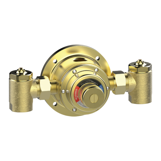
Series 61
Thermostatic Water
Controller
CAPACITIES – GPM SERIES 61
Pressure Drop PSI
5
Valve Number
61-10
2.5
61-15
3.5
61-25
6
1/4 gpm when properly installed in recirculated system.
CAPACITIES – LPM SERIES 61
Pressure Drop PSI
5
Valve Number
61-10
9.4
61-15
13.2
61-25
22.7
Minimum flow for 61-10 & 61-15 is 1/2 Gallon Per Minute
Minimum flow for 61-25 is 1 Gallon Per Minute
B
72906_6110_STD_DRW_NODIMS.pdf
A
C
DIMENSIONS
Valve Number
A N.P.T.
61-10
1/2"
61-15
1/2"
61-25
3/4"
Dimensions are for reference purposes only. For rough-in dimensions
please refer to Lawler's Revit/BIM models found at temperedwater.com.
temperedwater.com
5330 East 25 th St.
Indianapolis, IN 46218
Phone (317) 261-1212
Fax (317) 261-1208
10
20
30
45
60
Capacity – GPM
3.5
5.5
8
10
12
5.5
8.5
11
15
18
10
14
18
25
30
10
20
30
45
60
Capacity – LPM
13.2
22.8
30.3
37.8
45.4
20.8
32
41.6
56.7
68
37.8
53
68
94.6
113
A
B N.P.T.
C
1/2"
8-1/2"
1/2"
8-1/2"
3/4"
8-5/8"
temperedwater.com/patents
80
14
20
34
80
53
75.7
128
M 61 E
Advertisement

Related Manuals for Lawler 61 Series


Summary of Contents for Lawler 61 Series
- Page 1 61-25 3/4” 3/4” 8-5/8” Dimensions are for reference purposes only. For rough-in dimensions please refer to Lawler’s Revit/BIM models found at temperedwater.com. temperedwater.com/patents ASSE 1017 Approved Design and specifications subject to change without notice. ASSE Lead Free Certified M 61 E Please refer to temperedwater.com to ensure most...
- Page 2 75°F. A quick test is to momentarily turn on hot water so Lawler Thermostatic Valves adjust for changes in both input the thermostat warms up. If flow then starts, the temperature and pressure, maintaining constant output.
- Page 3 5. When temperature is correct, replace handle screw. If outlet temperature is to be 15°F or more higher than that on the label, contact factory or Lawler representative for a special thermostat. Series 61 cut away new...
- Page 4 Item Description 1/2” Part No. 3/4” Part No. Handle Screw 7628-00 7628-00 Handle 8062-00 8062-00 Cover O-Ring — — Cover Screw 7185-00 117-00 Cover — — (Available only in Cover & Spindle Assembly) Body Gasket — — Adjusting Screw 8262-00 8262-00 Spindle —...