Advertisement
Quick Links
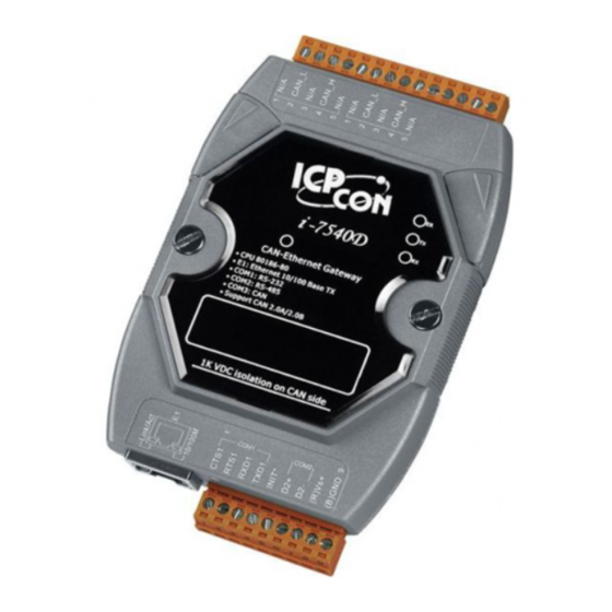
Packing List
In addition to this guide, the package includes the following items:
I-7540D-G / I-7540DM
/ I-7540D-UTA-G /
I-7540DM-UTA * 1
Wire Terminal * 32
Technical Support
service@icpdas.com
www.icpdas.com
For Desktop Web
I-7540D/I-7540DM Series Quick Start
(including in I-7540D-G
Resources
How to search for drivers, manuals and
spec information on ICP DAS website.
For Mobile Web
Model Name
Plastic Rail * 1
/ I-7540D-UTA-G)
Screw Driver * 1
Model Name
v2.0, Oct 2021
COM Cable
(CA-0910) * 1
P1
Advertisement

Related Manuals for ICP DAS USA I-7540D Series


Summary of Contents for ICP DAS USA I-7540D Series
- Page 1 I-7540D/I-7540DM Series Quick Start v2.0, Oct 2021 Packing List In addition to this guide, the package includes the following items: I-7540D-G / I-7540DM Plastic Rail * 1 COM Cable / I-7540D-UTA-G / (including in I-7540D-G (CA-0910) * 1 I-7540DM-UTA * 1 / I-7540D-UTA-G) Wire Terminal * 32 Screw Driver * 1...
-
Page 2: Hardware Installation
--------------------------------------------------------------------- Hardware Installation Before using I-7540D / I-7540DM series devices, some things must be done. Step 1: Prepare one I-7540D / I-7540DM series device Step 2: Determine if the CAN Bus terminal resistor is needed or not Check the application structure, and determine if the terminal resistor is needed to be enabled or not. -
Page 3: Autoexec.bat
Step 3: Connect the CAN port, ethernet and power line of the module Connect the (R)Vs+ and (B)GND pins of the I-7540D module to the DC power supply (10~30VDC). And connect the Ethernet ports of the I-7540D and the PC with standard network cable respectively. -
Page 4: Utility Tool
---------------------------------------------------------------- Utility tool When users want to change the CAN/COM and Ethernet parameters of I-7540D, Utility tool may be needed. Step 1: Install the I-7540D Utility tool The software is located at: https://www.icpdas.com/en/download/show.php?num=919&m odel=I-7540D-G Step 2: Setting up I-7540D module The default network setting of the I-7540D is shown below. - Page 5 Step 3: Connect to I-7540D module Click the “Connect” button to connect with the I-7540D module.
- Page 6 Step 4: Configure the module parameters After connecting with the I-7540D, you can modify the CAN parameters and network status of the module. IP/Gateway/Mask/ Web ID/Password CAN Parameters CAN Pair RS-232/RS485 Status Detail information about how to configure module parameters, please refer to section “3.