
Related Manuals for MIMSAL LS

Summary of Contents for MIMSAL LS
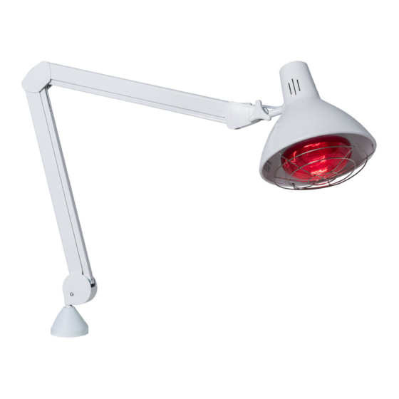
- Page 1 USER MANUAL EXAMINATION LAMP LS LED | LS INFRA | LS INFRA TIMER F3P34 Rev. 01 20.06.2022...
- Page 2 • 2014/30/EU Electromagnetic Compatibility (E.M.C) This manual’s content may be modified in part or in whole by MISMAL without prior notice in order to make changes and improvements. MIMSAL has a Customer Support service available. Your team: MIMSAL TRADE S.L.
-
Page 3: Table Of Contents
TABLE OF CONTENTS 1.Safety instructions 2. Brief description 3. Installation and supports 3.1 Trolley Stand 3.2 AH Table Clamp 3.3 Wall B Support 3.4 Rail Plus Bracket 3.5 Extension arm 4. Operation of the lighting unit 4.1 Check before each use 4.2 Operation of the lighting unit head 4.3 Articulated arms measurement details 5. - Page 4 SYMBOLS INSTRUCTIONS DECLARATION OF CONFORMITY ITEM CODE BATCH NUMBER MANUFACTURING DATE NAME AND ADDRESS OF THE MANUFACTURER ELECTRONIC WASTE RECYCLING ELECTRICAL INSULATION CLASS Class II MINIMUM DISTANCE TO THE ILLUMINATED OBJECT AMBIENT TEMPERATURE Shows the permitted ambient temperature of between -25°C and 70°C for transportation and storage.
-
Page 5: Safety Instructions
2. The manufacturer is not responsible for any damage caused by improper use! 3. The final user is responsible for the product’s installation and MIMSAL accepts no responsibility. 4. The manufacturer is responsible for the safety of the lamp only if repairs and modifications are... -
Page 6: Brief Description
2. BRIEF DESCRIPTION INTENDED USERS These operating instructions are intended for the users who use, clean, and disinfect MISMAL lighting units. INTENDED USE This lighting unit is intended for carrying out very meticulous work that requires a high degree of precision and good lighting. INDICATION The light is only used to provide optimal visibility of the surface under examination. -
Page 7: Installation And Supports
3. INSTALLATION AND SUPPORTS Before starting to install the device, check that the content is in good condition and that it has not been damaged or degraded during transportation. Claims will only be accepted if the vendor or the carrier is notified immediately. All claims must be made in writing. -
Page 8: Trolley Stand
3.1 TROLLEY STAND MODEL DESCRIPTION 09655 TROLLEY STAND 4 Kg 4 Kg rolling base 09651 TROLLEY STAND 8,8 Kg 8.8 Kg rolling base Install the accessory without the lighting unit installed on it. It is the customer’s responsibility to ensure that the surface that it is attached to is secure and sufficiently strong. -
Page 9: Ah Table Clamp
3.2 AH TABLE CLAMP MODEL DESCRIPTION B010190 AH TABLE CLAMP Table clamp Install the accessory without the lighting unit installed on it. It is the customer’s responsibility to ensure that the surface that it is attached to is secure and sufficiently strong. Check regularly that the unit is still stable in order to avoid the possibility of the lighting unit falling down. -
Page 10: Wall B Support
3.3 WALL B SUPPORT MODEL DESCRIPTION B0101800 WALL B SUPPORT Reinforced wall B bracket. 7 cm shaft-wall separation. Install the accessory without the lighting unit installed on it. It is the customer’s responsibility to ensure that the surface that it is attached to is secure and sufficiently strong. -
Page 11: Rail Plus Bracket
3.4 RAIL PLUS BRACKET MODEL DESCRIPTION 82026 RAIL PLUS BRACKET Bracket for mounting on an ICU rail. Install the accessory without the lighting unit installed on it. It is the customer’s responsibility to ensure that the surface that it is attached to is secure and sufficiently strong. -
Page 12: Extension Arm
3.5 EXTENSION ARM MODEL DESCRIPTION Extension arm including Wall B Bracket. Provides an B0101S0 EXTENSION ARM additional 40 cm, with horizontal rotation along both axes. Install the accessory without the lighting unit installed on it. It is the customer’s responsibility to ensure that the surface that it is attached to is secure and sufficiently strong. -
Page 13: Operation Of The Lighting Unit
4.2 OPERATION OF THE LIGHTING UNIT HEAD Lighting unit with simple and ergonomic operation for intuitive handling. For LS LED, LS INFRA: - The power switch is on the power cable. - Select the switch position. I (On) | 0 (Off). -
Page 14: Safety Functions
5. SAFETY FUNCTIONS 5.1 VOLTAGE DROP In the event of a network voltage drop, the light will automatically switch off. 5.2 POWER CUTS In the event of a total power cut, the light will switch off. As soon as voltage is reestablished on the network, it can be turned on again using the most recent established parameters. -
Page 15: Disinfection
6.3 DISINFECTION SAFETY Check the general safety instructions. DISINFECTION PROCESS The disinfection process is done using a cloth. The hygiene guidelines and safety measures for the disinfection processes to be used must be defined by the operator. We recommend using MELISEPTOL disinfectant made by Braun Melsungen and/or “neoform MED rapid”... -
Page 16: Lighting Unit Head
7.2 LIGHTING UNIT HEAD The following inspections/maintenance must be carried out: 1. Check for any possible anomalies, cracks, deformations in plastic pieces and seals. 2. Carry out electrical safety tests. 3. Extended operational test. 4. Damage to the paint. 7.3 REPAIRS The following indications must be followed: - The product may only be opened and repaired by the manufacturer. -
Page 17: Technical Data
9. TECHNICAL DATA PHOTOMETRIC AND LS LED LS INFRA LS INFRA TIMER ELECTRICAL DATA Light Source LED 7,5W IR E-27 150W / 250W Base E-27 Ceramic Timer SI / 0 – 15 min Protection Class Class II Voltage 220/240 V... -
Page 18: Electromagnetic Emissions
MODEL GROSS WEIGHT NET WEIGHT BOX DIMENSIONS B0101800 WALL B SUPPORT 0,25 KG 0,20 KG 91 x 221 x 122 mm B010190 AH TABLE CLAMP 0,37 KG 0,29 KG 91 x 221 x 122 mm 82026 RAIL PLUS BRACKET 0,24 KG 0,19 KG 115 x 175 x 75 mm 09651... -
Page 19: Warranty
(10) days of detecting the Product defect. Upon receipt of this email, MIMSAL will try to see if it is possible to resolve the incident remotely, in which case it will respond to the Buyer with instructions on how to proceed or, conversely, if the Product must be sent to MIMSAL to be examined and, if necessary, repaired or replaced. -
Page 20: Industrial And Intellectual Property
The Buyer is obliged to abstain from registering in their name or in the name of third parties, brands or trademarks that are identical or similar to those used by MIMSAL or that could cause confusion for customers regarding the identity or character of MIMSAL or of the Products. -
Page 21: Declaration Of Conformity
DECLARAN BAJO SU RESPONSABILIDAD QUE EL PRODUCTO DECLARE UNDER THEIR RESPONSIBILITY THAT THE PRODUCT Nombre del producto Product name Referencia - Modelo LS010316LED - LS LED Reference - Model Directivas 2014/35/EU (LVD) Low Voltage Directive Class II 2014/30/EU Electromagnetic Compatibility (E. M. C) - Page 22 Referencia - Modelo E020412 - LS INFRA 150 Reference - Model E02041250 - LS INFRA 250 E020412T - LS INFRA 150 TIMER E02041250T - LS INFRA 250 TIMER Directivas 2014/35/EU (LVD) Low Voltage Directive Class II 2014/30/EU Electromagnetic Compatibility (E. M. C)
-
Page 23: Certificate Iso 9001
20 April 2025 – This is to certify that the management system of MIMSAL TRADE, S.L. Calla Mollet 17, Pol. Ind Palou Nord, 08401, Granollers, Barcelona, Spain has been found to conform to the Quality Management System standard: ISO 9001:2015 This certificate is valid for the following scope: Manufacturing and distribution of medical devices for the lighting market. - Page 24 MIMSAL TRADE S.L. C/ Mollet, 17 Polígono Industrial Palou Nord 08401 – Granollers (Barcelona) SPAIN Tel. +34 930 139 860 mimsal@mimsal com www.mimsal.com F3P34 Rev. 01 20.06.2022...
Need help?
Do you have a question about the LS and is the answer not in the manual?
Questions and answers